- How to program a CAN-BUS arduino shield to control car windows?
- 3 Answers 3
- Arduino controlling car windows?
- 1 Answer 1
- How to program a CAN-BUS Arduino shield to control car windows?
- 2 Answers 2
- 67 car projects
- Race Car Dashboard (Online Connectivity)
- MAX009
- From BT To WiFi: Creating WiFi Controlled Arduino Robot Car
- Bluetooth Controlled Car
- Track ME
- Obstacle Avoiding Car
- Arduino 4WD RC Car
- Smart Parking
- Car Sensor monitoring & Alarm
- Biometric Car Entry — True Keyless Car
- ED BMSdiag
- Parking Radar Sensor
- Getting Started with the Smartcar Platform
- Bluetooth RC Car with Remote Arduino
How to program a CAN-BUS arduino shield to control car windows?
My project is to control car windows using voice recognition. I have successfully controlled some LED’s using the EasyVR arduino shield using and arduino MEGA. Now I want to take control of the windows using the CAN-BUS arduino shield.
Because the car that I own doesn’t have an OBD-II connector, I am using two arduinos with two CAN-BUS arduino shields making one a sender and the other a receiver. Now I don’t know how to program the CAN-BUS arduino shield to make a simulation of the car’s windows ?
3 Answers 3
- CAN bus is a communication protocol(like RS485, but more reliable). It does not control anything itself.
- If windows, headlights or other devices are controlled with I/O and I/O is communicating with CAN bus then you might be able to control windows, headlight etc.
- CAN bus shield for Arduino has Microchip MCP2515 CAN controller with MCP2551 CAN transceiver, so you do not need 2 of them.
With colleague we are working with electric vehicle project and we are able to monitor and control using Arduino and CAN bus shield.
If you want to control windows, i would consider possibility to try this setup:
- Disconnect windows from button and power.
- Put 2 relays, to have H-bridge(to move up and down)to control window motor http://www.ebay.com/itm/1pcs-5V-2-Channel-Relay-Module-for-Arduino-PIC-ARM-DSP-AVR-Electronic-/261099571172?pt=LH_DefaultDomain_0&hash=item3ccabf47e4
- Put some limit switches, to turn of relay when window is closed or fully opened.
- Control these relays with Arduino.
In my opinion this would be easiest way. And you won’t have to go throw CAN bus.
EDIT Also provide some specification of car. If it does not have OBD II socket maybe its not new one, so the windows will be controlled with buttons, i guess.

The CAN shield can be both a receivers and a transmitter, you shouldn’t need two of them (unless you are bridging two networks together.
Unfortunately, operating the windows is not something for which there is a standard message. And indeed the window controllers may actually be on a LIN bus (not CAN). I’m not sure there is a LIN shield, but it’s a relatively simple physical layer chip and a UART, so you should be able to rig something up.
Then you will have to reverse engineer the messages.
If you can find out from a workshop manual what the CAN/LIN buses look like, you should be able to find somewhere to tap into the right bus.
Then monitor the bus and operate the window switch to see if a new message appears, or if some particular bits change in a regular message. There will often be sequence counters and checksums within the messages which you will also have to understand in order to correctly replay the appropriate message.
Arduino controlling car windows?
All windows are power windows control in Hyundai i20 but only the driver window has auto up and auto close features.
Now, is there a way to close or open the remaining 3 windows with just one touch like in driver window??
What Arduino parts or materials are necessary to achieve these auto up and down features?? Thanks.

1 Answer 1
It is possible that the windows are controlled via CAN or LIN bus, which means you have to send a sequence of data to them. Pretty easy for a microcontroller — if you know which data to send. Since window open/close function is a security issue, the data might also be not that trivial, and contain some kind of encryption, CRC, or other features. And. the controller of the car might notice that there’s something going on, and at least throw an error.
But it’s also possible that an i20 has just simple motors at the windows.
First of all, your driver windows lever has two contacts for each position. Touched with little pressure moves the window until you release the button, a bit more pressure makes it move until the end. I doubt that the other levers have the necessary contacts for that.
The windows will just have a motor connected to 12V to move in one direction, and connected in reverse polarity to move in the other. What you are looking for is a H-bridge, which allows exactly that. It can be made of four relays, but there are fully integrated ICs for this. Have a look at Infineon Trillic series. These ICs allow easy direction switching, easy PWM for power control, and — that’s important — overcurrent protection. Overcurrent protection allows to detect when the window is fully opened/closed and so when to switch off the motor. I will also detect when something like an arm is in the way. And they can power a motor from 12V, while they can be controlled by the typical 5V or 3.3V from microcontrollers.
I don’t know if such ICs are available ready for use in the adurino world, but this should be no problem for someone who can solder.
How to program a CAN-BUS Arduino shield to control car windows?
My project is to control car windows using voice recognition. I have successfully controlled some LEDs using the EasyVR Arduino shield using and Arduino MEGA. Now I want to take control of the windows using the CAN-BUS arduino shield.
Because the car that I own doesn’t have an OBD-II connector, I am using two Arduinos with two CAN-BUS Arduino shields making one a sender and the other a receiver. How can I program the CAN-BUS Arduino shield to make a simulation of the car’s windows?
2 Answers 2
What model car do you have? Most cars do not have the ability to control power windows from the car computer. Late model cars will have the ability to control the window motors using bidirectional functions on a scan tool. On any car, the window motors have two wires, if one wire is given power and one ground it will spin if you switch the wire that gets power with the wire that gets ground it spin in the opposite direction. In my experience the way power windows work are both wires are ground while the switch is in the neutral position and by flipping the switch the switch will disconnect one of the grounds and replace it with a power. Find a wiring diagram for your car, and look at how the windows are controlled.
Connect the ground wire to the normally closed (when no power is applied to the relay this is connected to the output wire) side of both relays and the 12v power to the normally open (when power is applied to the relay this is connected to the output wire)side of both relays.
In order to control the relay breakout board you choose one io pin per relay and set it as an output, then connect those pins to the corresponding pin on the breakout board. Set one of the pins to high (you apply power to one relay) the motor now has a power and a ground connection, set the opposite pin high to spin the other way.
I would place this in the driver side door underneath the window master switches because you can have access to every windows wires as they come out of the master switch.
Some late model cars will have a different set up than the one described, but the window motor will only have two wires (it is just a brushed DC motor) just find the window motor and hookup there.
67 car projects
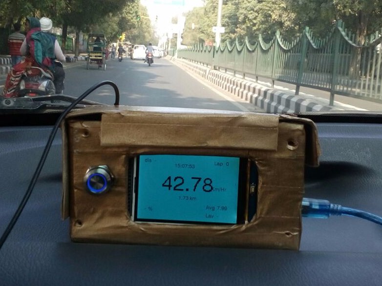
The project was initially designed to acquire real-time race car data for BAJA-SAE competitions.
Race Car Dashboard (Online Connectivity)
Project showcase by Team Jatayu
- 45,106 views
- 69 comments
- 64 respects
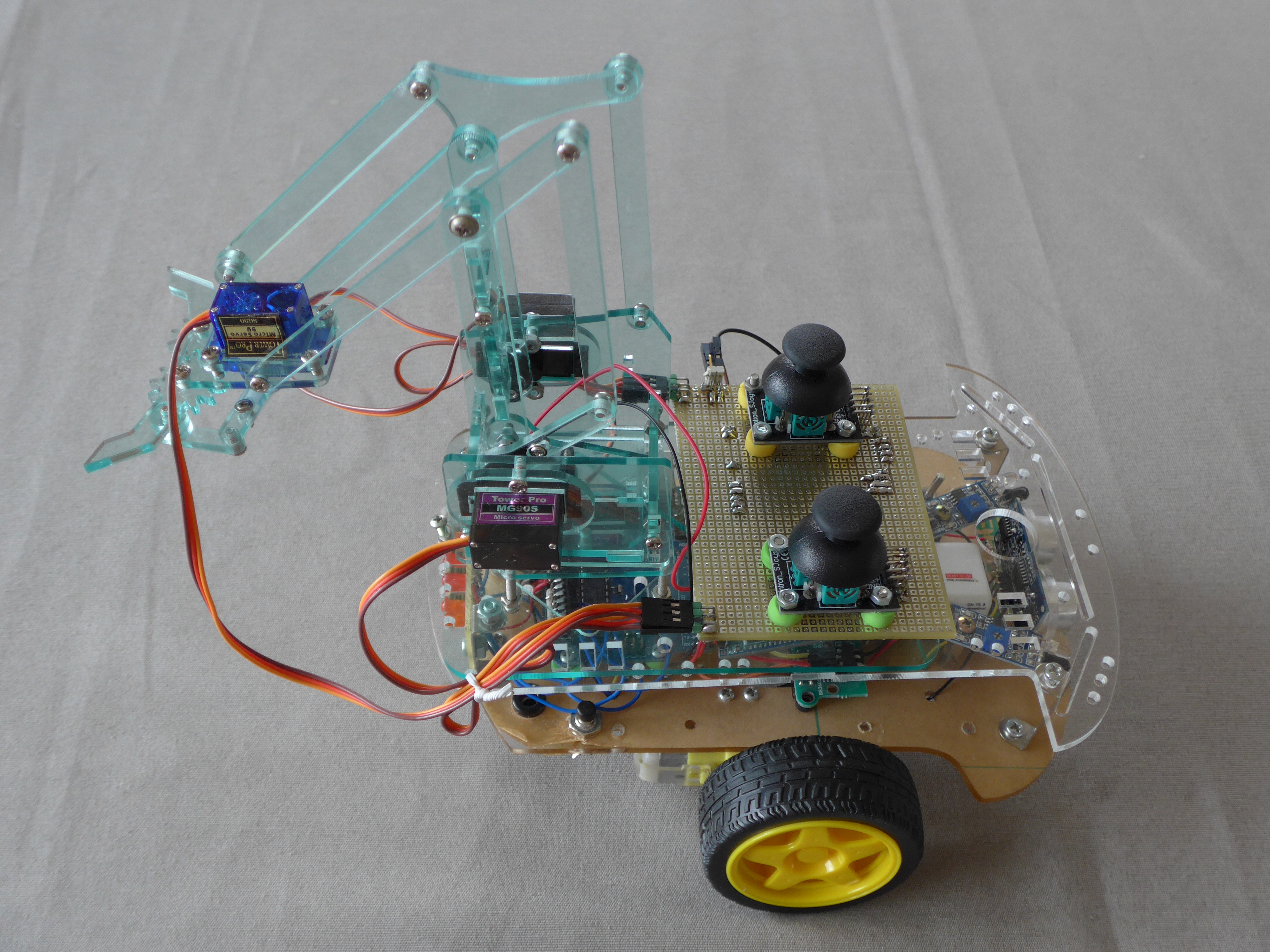
MeArm mounted on smart robot car controlled by 2 Arduino UNOs
MAX009
Project showcase by benoitdr
- 30,586 views
- 56 comments
- 63 respects
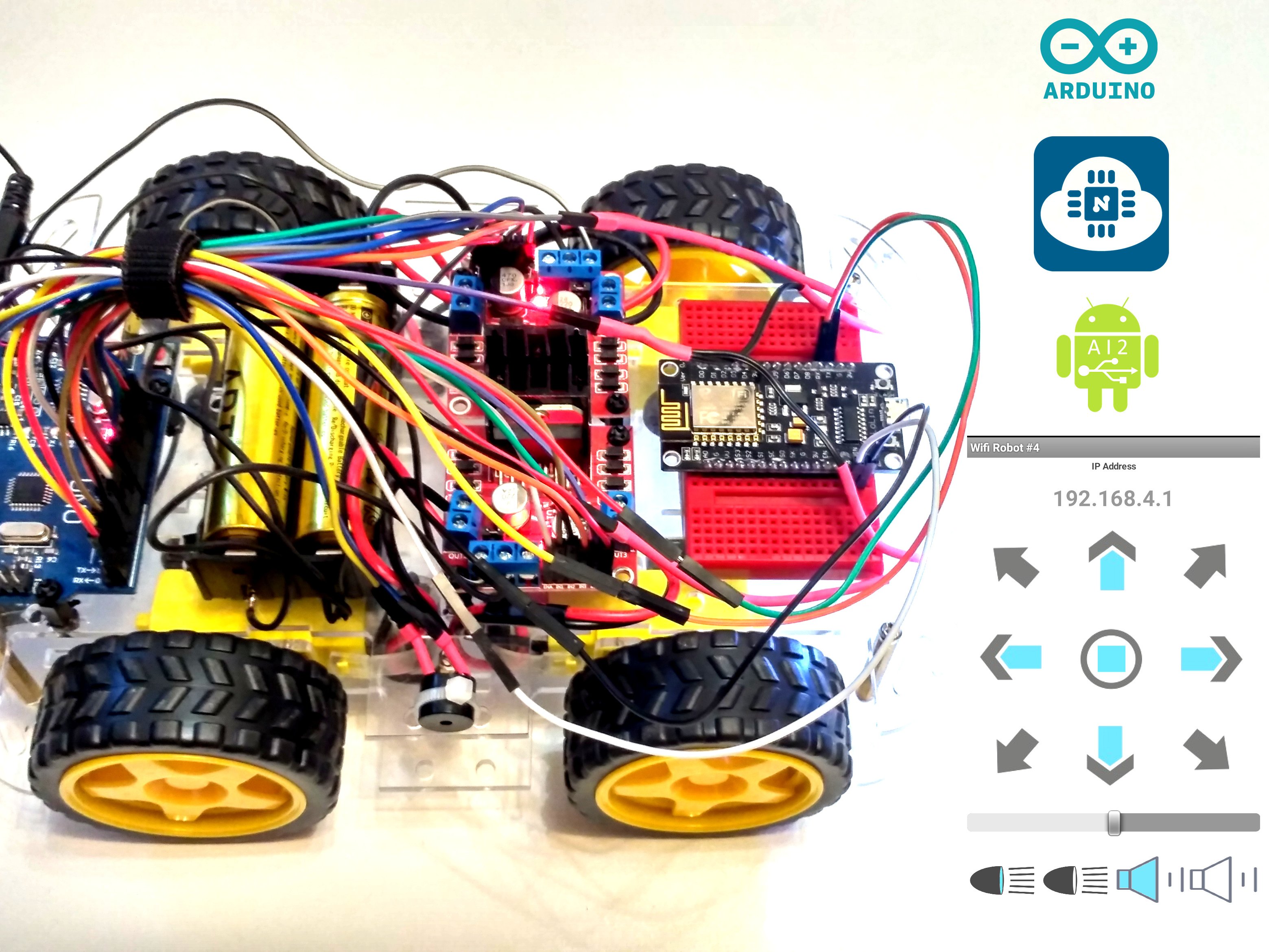
NodeMCU ESP8266 in access point mode: the simplest way to make Wi-Fi controlled Robot Car from Bluetooth Arduino Robot Car + Android App.
From BT To WiFi: Creating WiFi Controlled Arduino Robot Car
- 78,838 views
- 42 comments
- 126 respects
![]()
This project shows how you can build a car which can be controlled by your smartphone using an android application via Bluetooth.
Bluetooth Controlled Car
Project tutorial by JANAK13
- 47,660 views
- 37 comments
- 63 respects

Track ME is a «small» GPS, SD Card, and GSM Shield controlled by an Arduino Mega. Call me and get my location.
Track ME
Project tutorial by Hugo Gomes
- 60,253 views
- 33 comments
- 96 respects
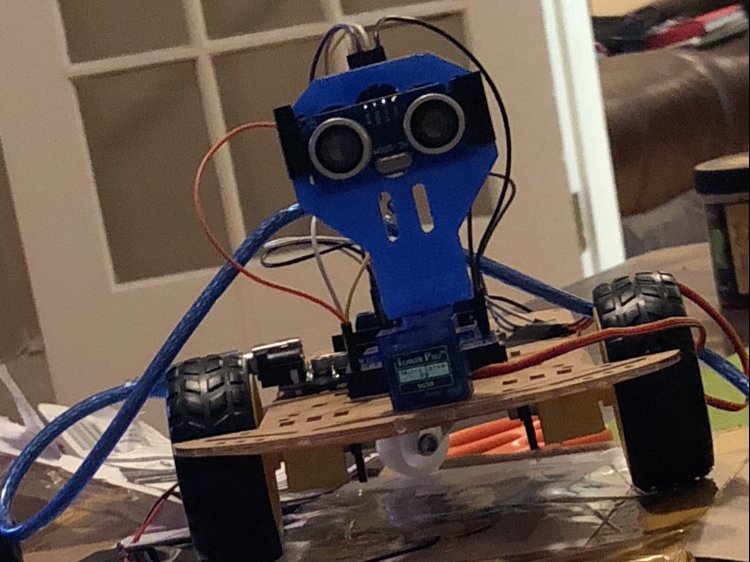
An Arduino controlled car that avoids obstacles (ie. walls or objects in front of it).
Obstacle Avoiding Car
Project showcase by Team Adam
- 68,824 views
- 21 comments
- 74 respects
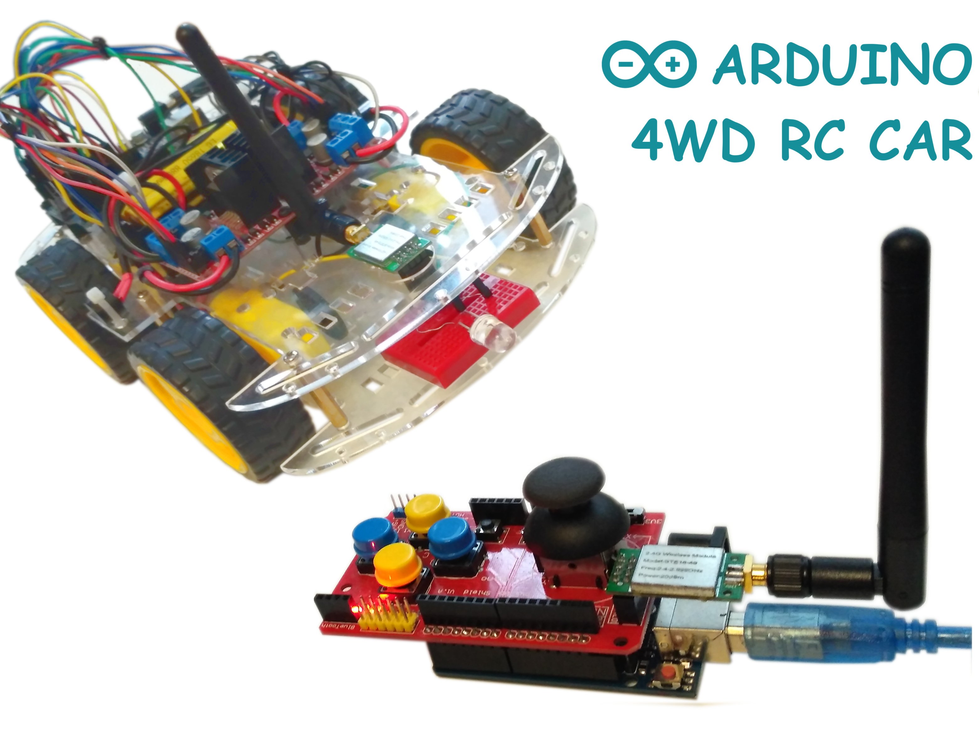
How to make an Arduino 4WD RC Car with Joystick Controller (Arduino Uno | Joystick Shield | nRF24L01+PA+LNA).
Arduino 4WD RC Car
Project tutorial by Andriy Baranov
- 56,291 views
- 18 comments
- 109 respects
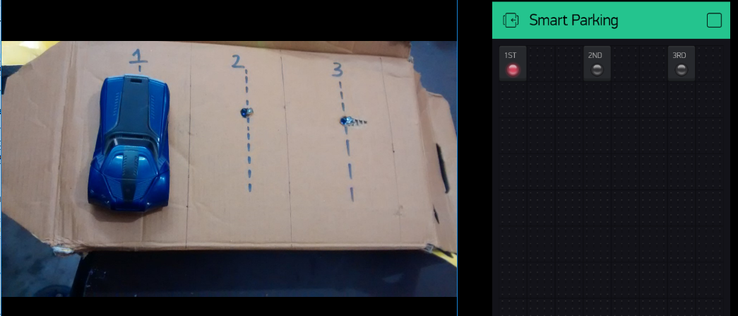
A system that tells you about the parking slots of an area.
Smart Parking
- 48,134 views
- 15 comments
- 50 respects
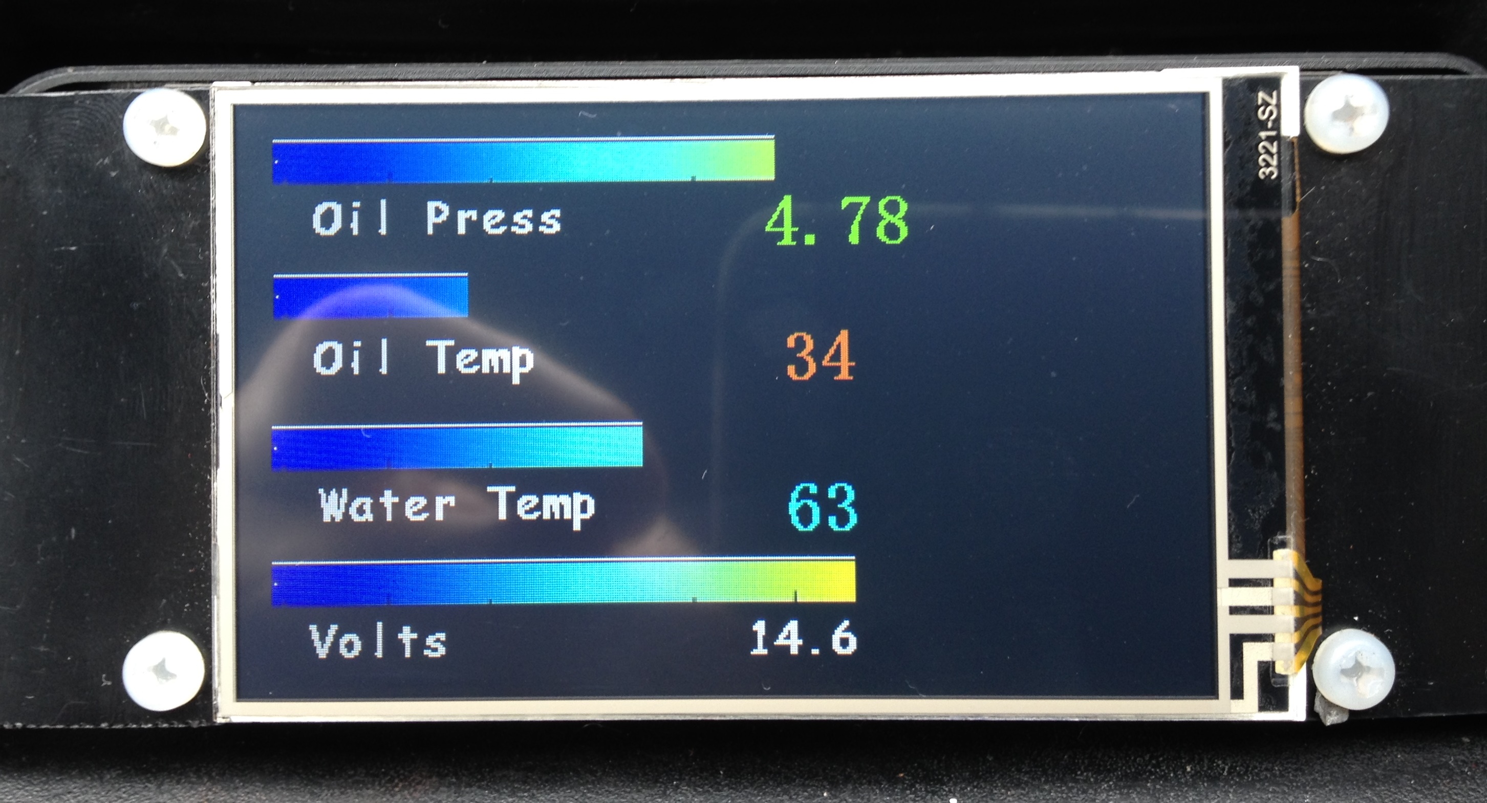
Monitor Oil Temp and Pressure, Water Temp, Voltage, Fuel level. Display on Nextion display or Nokia LCD
Car Sensor monitoring & Alarm
Project showcase by petemnz
- 42,137 views
- 14 comments
- 67 respects

Why are even the modern day cars are not equipped with biometric entry system? Here is an attempt on a Toyota C-HR.
Biometric Car Entry — True Keyless Car
Project showcase by Rajeev Velikkal
- 17,779 views
- 13 comments
- 56 respects
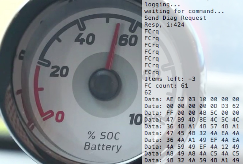
CAN bus hack for reading the battery diagnostics form an electric car.
ED BMSdiag
Project tutorial by MyLab-odyssey
- 15,473 views
- 13 comments
- 37 respects
Use three HC-SR04 ultrasound sensors and two battery displays to show you how close the obstacles are and from which side.
Parking Radar Sensor
Project tutorial by SurtrTech
- 18,317 views
- 12 comments
- 64 respects
A versatile & easy to use vehicle platform for hobby-grade projects: You focus on application logic and the library takes care of the rest.
Getting Started with the Smartcar Platform
- 22,296 views
- 11 comments
- 56 respects

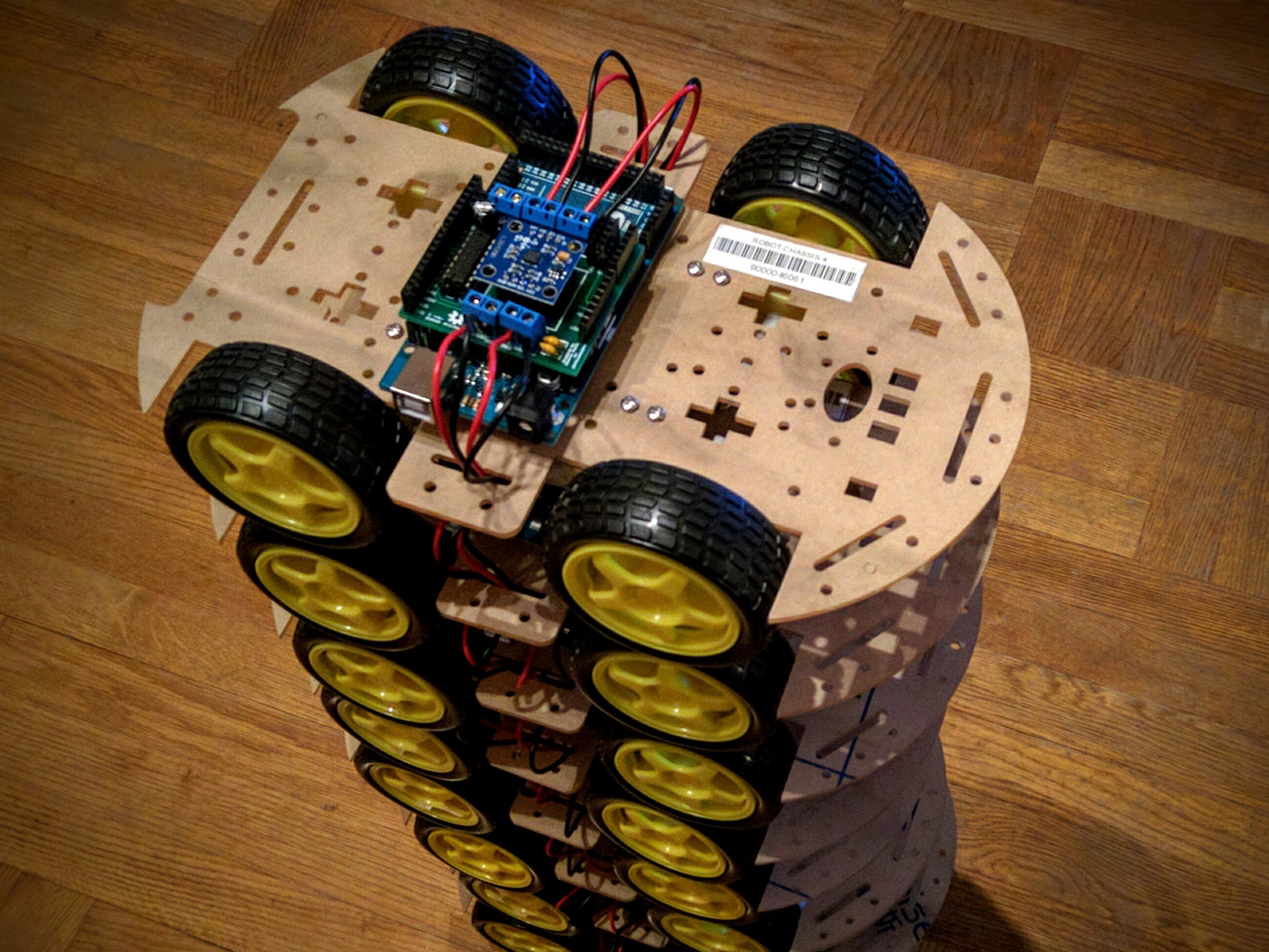
An Arduino car project based on the RoboRoverM1 chassis.
Bluetooth RC Car with Remote Arduino
A Bluetooth-enabled RC Car that uses Remote Arduino to allow another Windows device to control it.
_ztBMuBhMHo.jpg) |
| × | 1 | ||
| × | 1 | |||
| × | 1 | |||
 |
| × | 1 |
In this project, we will modify an RC car to allow it to be controlled using Windows Remote Arduino via a Bluetooth connection! With Remote Arduino, it is possible to build a Universal Windows Application which will direct the car in any direction. We used a Lumia phone running Windows 10 to control the car with the built-in accelerometer!
You can download the «samples» repository here. This sample is «remote-controlled-car» inside the Win10 folder. Make sure to clone the repository recursively so that you also obtain a copy of the library (more info in the readme)!
If you’d prefer to create your own project, follow the project set up guide here
You can find the Windows Remote Arduino repository here
See the pictures below for an image-based overview of the set up process.
We’re going to remove the existing circuitry and add our own Arduino and motor controller (shield). You can technically use the existing circuitry to drive the motors, but the work involved in doing so can be much more complicated and varies wildly from car to car! This solution, while requiring more parts, is much more general. At any rate, make sure to remove the battery before taking the car apart!
- Unscrew the bottom frame from the rest of the car
- Remove the wire connectors from the circuit board while removing the top of the frame from the bottom
- Unscrew the circuit board and cut the wires away. You can discard the board if you wish, we won’t need it again.
- Prepare the Arduino and motor shield by sliding the shield down directly over the Arduino.
- Verify that all jumpers on the motor shield are in the correct orientation. The Velleman ka03 I am using has five total jumpers! Four are used to select the control pins for the motors. The most important one controls where the motor power comes from, so you’ll need to decide if the RC car battery will continue to power only the motors (EXT) or the Arduino as well (INT). If you use internal power, you’ll need a barrel jack to hook the power/ground wires up to before inserting it onto the Arduino’s DC port.
- Attach the leads from each motor to a terminal on the motor shield. I’ve hooked up the front (left/right) motor to terminal 1 and the back (forward/back) motor to terminal 2.
- Attach the power leads to either the external power terminal on the motor shield (EXT) or to a barrel jack which will be plugged into the Arduino to power both devices at the same time (INT). I am using internal power, which is more than sufficient for the car that I am using!
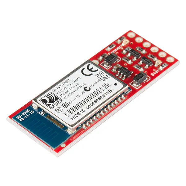
- Last, hook up the Bluetooth device to the Arduino by connecting a wire from TX on the Arduino to RX on the Bluetooth device and vice-versa. Also connect it to power and ground!
That is the last of the hardware setup steps! You’ll eventually want to secure the board down using a custom mount or zip ties!
Note: This RC Car that I am using uses a small motor for left/right which is designed to turn until it stalls, which then draws a lot of current. It is technically working as intended, and is OK to leave the way it is as long as your motor shield can supply the power it draws. However, I’ve gone ahead and added a 5w 10Ω resistor to the front motor to reduce the amount of current required.
Download the sample repository here. You’ll find «remote-controlled-car» inside the W10 directory. This sample uses a Windows 10 phone’s accelerometer to drive the car! If you are using a different pin configuration to control the motor shield, you’ll want to locate and change the pin values for the following variables inside ControlPage.xaml.cs:
- FB_DIRECTION_CONTROL_PIN = 8;
- FB_MOTOR_CONTROL_PIN = 9;
- LR_DIRECTION_CONTROL_PIN = 2;
- LR_MOTOR_CONTROL_PIN = 3;
Or just modify the source to use the default (zero-argument) constructor of BluetoothSerial which will attempt to connect to each Bluetooth device you are paired to until it is successful with one.
If you’d prefer to create your own project, follow the project set up guide here.
As usual with Windows Remote Arduino, you only need to program your Arduino device to run «StandardFirmata» (you can find this in the «Firmata» folder in the included libraries. Just make sure to change the baud rate in the sketch to match your device. The BlueSmirf runs at 115200 by default. There are more detailed instructions here.


