- Bad linux arm zimage magic
- Bad Linux ARM zImage magic! on iMX6UL
- ODROID
- I can’t boot up due to «Bad Linux ARM zImage magic!»
- I can’t boot up due to «Bad Linux ARM zImage magic!»
- Re: I can’t boot up due to «Bad Linux ARM zImage magic!»
- Re: I can’t boot up due to «Bad Linux ARM zImage magic!»
- 5. Загрузка образа ядра
- Проблемы при загрузке ядра 2.6 u-boot-ом
- Building embedded Linux for the Terasic DE10-Nano (and other Cyclone V SoC FPGAs)
- Step 0 — Preparation
- Step 0.1 — Installing Quartus Prime
- Step 0.2 — Installing SoC EDS
- Step 0.3 — Setting the MSEL switches
- Step 1 — Creating and modifying the hardware design
- Step 1.1 — Getting the GHRD
- Step 1.2 — Upgrading IP
- Step 1.3 — Modifying the GHRD
- Step 1.4 — Creating a custom IP
- Step 1.5 — Creating a custom component
- Step 1.6 — Adding the custom component to the hardware design
- Step 1.7 — Generating HDL
- Step 1.8 — Preparing synthesis
- Step 1.9 — Synthesizing the system
- Step 2 — Generating the preloader
- Step 2.1 — Configuring the preloader
- Step 2.2 — Compiling the preloader
- Step 3 — Setting up U-Boot
- Step 3.1 — Getting and setting up the GCC toolchain
- Step 3.2 — Getting and compiling U-Boot
- Step 3.3 — Setting up the boot script
- Step 4 — Generating and compiling the device tree
- Step 5 — Testing the system
- Step 5.1 — Creating an image file and mounting it
- Step 5.2 — Creating partitions
- Step 5.3 — Creating the file systems
- Step 5.4 — Write the SD card image to an actual SD card
- Step 5.5 — Testing the system
- Step 6 — Configuring and compiling the Linux kernel
- Step 6.1 — Getting and setting up the GCC 7.x toolchain
- Step 6.2 — Getting the Linux kernel source code
- Step 6.3 — Configuring the Linux kernel
- Step 6.4 — Compiling the kernel
- Step 7 — Generating a root file system
- Step 7.1 — Configuring Buildroot
- Step 7.2 — Configuring BusyBox
- Step 7.3 — Generating the root file system
- Step 8 — Testing the system again
- Step 9 — Driving the LEDs with a user-space application
- Step 10 — Driving the LEDs with a kernel module
- Final words
Bad linux arm zimage magic

- Home
- :
- i.MX Forums
- :
- i.MX Processors
- :
- Bad Linux ARM zImage magic! on iMX6UL
Bad Linux ARM zImage magic! on iMX6UL
- Subscribe to RSS Feed
- Mark Topic as New
- Mark Topic as Read
- Float this Topic for Current User
- Bookmark
- Subscribe
- Mute
- Printer Friendly Page
- Mark as New
- Bookmark
- Subscribe
- Mute
- Subscribe to RSS Feed
- Permalink
- Email to a Friend
- Report Inappropriate Content
We’ve built a few custom boards based on the iMX6UL with eMMC on SDIO2. We’ve had a CM build a few boards for us which are being validated before we build a larger run of PCBs.
The first set of boards turned on no issue, and a console log on initial boot looks good:
U-Boot 2015.04-imx_v2015.04_4.1.15_1.0.0_ga+gd7d7c43 (Sep 09 2016 — 19:01:59)
CPU: Freescale i.MX6UL rev1.1 at 396 MHz
CPU: Temperature 36 C
Reset cause: POR
Board: MX6UL 14×14 EVK
DRAM: 512 MiB
MMC: FSL_SDHC: 0, FSL_SDHC: 1
*** Warning — bad CRC, using default environment
Display: TFT43AB (480×272)
Video: LCDIF@0x21c8000 is fused, disable it
In: serial
Out: serial
Err: serial
switch to partitions #0, OK
mmc1(part 0) is current device
Net: Ethernet@0x20b4000 is fused, disable it
FEC1 MXC: board_eth_init:failed
No ethernet found.
Normal Boot
Hit any key to stop autoboot: 0
switch to partitions #0, OK
mmc1(part 0) is current device
switch to partitions #0, OK
mmc1(part 0) is current device
reading boot.scr
** Unable to read file boot.scr **
reading zImage
6649752 bytes read in 163 ms (38.9 MiB/s)
Booting from mmc .
reading imx6ul-14×14-evk-btwifi.dtb
34507 bytes read in 18 ms (1.8 MiB/s)
Kernel image @ 0x80800000 [ 0x000000 — 0x657798 ]
Interestingly, we have 2 more panels of boards which do the following:
U-Boot 2015.04-imx_v2015.04_4.1.15_1.0.0_ga+gd7d7c43 (Sep 14 2016 — 12:12:28)
CPU: Freescale i.MX6UL rev1.1 at 396 MHz
CPU: Temperature 35 C
Reset cause: POR
Board: MX6UL 14×14 EVK
DRAM: 512 MiB
MMC: FSL_SDHC: 0, FSL_SDHC: 1
*** Warning — bad CRC, using default environment
Display: TFT43AB (480×272)
Video: LCDIF@0x21c8000 is fused, disable it
In: serial
Out: serial
Err: serial
MMC: no card present
Net: Ethernet@0x20b4000 is fused, disable it
FEC1 MXC: board_eth_init:failed
No ethernet found.
Normal Boot
Hit any key to stop autoboot: 0
MMC: no card present
MMC: no card present
MMC: no card present
Booting from net .
No ethernet found.
No ethernet found.
Bad Linux ARM zImage magic!
What does not make sense at all is that we’ve successfully flashed the same image over USB into both boards, and burned efuses the same in both boards with the following:
Uboot is also coming up, so we know we have something successfully done with eMMC.
Any ideas what may be going on here? We’ve replaced eMMC and reflashed. We’ve also used the DDR stress tester and see that pass well. Definitely something in HW, but nothing is really making sense here.
Источник
ODROID
I can’t boot up due to «Bad Linux ARM zImage magic!»
I can’t boot up due to «Bad Linux ARM zImage magic!»
Post by luke » Tue Mar 29, 2016 6:00 pm
I’m using XU4 board, and I can’t boot up now, here is the log messages.
And I couldn’t find boot.ini file when I connect to sdcard to PC.
Please help me to find out how to solve this problem.

Re: I can’t boot up due to «Bad Linux ARM zImage magic!»
Post by odroid » Tue Mar 29, 2016 6:03 pm
Which OS image did you flash? What is the file name of the OS image?
Did you use the «VERIFY» button on our Win32DiskImager when you flashed the OS image?
http://odroid.com/dokuwiki/doku.php?id= . diskimager
Re: I can’t boot up due to «Bad Linux ARM zImage magic!»
Post by luke » Wed Mar 30, 2016 11:21 am
Thanks for your comment.
Actually, I built my own kernel, and download it with below site.
http://odroid.com/dokuwiki/doku.php?id= . ng_android
When I was downloading, I made a mistake to send it below command.
fatload mmc 0:1 40008000 zImage-dtb
I just wrote below command only.
movi write kernel 0 40008000
After that, I couldn’t boot up this board. and this log always is shown.
Let me ask something, even when I build my own kernel , do I have to do VERIFY by using tool that you mentioned?
Источник
5. Загрузка образа ядра
Образами ядра, генерируемыми процессом сборки ядра, являются либо файл без сжатия «Image», либо сжатый файл zImage.
Несжатый образ Image, как правило, не используется, так как он не содержит легко идентифицирумое магическое число. Практически повсеместно предпочтение отдаётся использованию сжатого формата zImage.
zImage имеет ряд преимуществ в дополнение к магическому числу. Как правило, декомпрессия образа быстрее , чем чтение с какого-либо внешнего носителя. Целостность образа может быть гарантирована, так как любые ошибки приведут к ошибке декомпрессии. Ядро знает свою внутреннюю структуру и состояние, которое позволяет получить лучший результат, чем общие внешние методы сжатия.
zImage имеет в своём начале магическое число и некоторую полезную информацию.
Таблица 2. Используемые поля в заголовочном коде zImage
Смещение в zImage
Магическое число, используемое для идентификации этого zImage Linux для ARM
Адрес, где zImage начинается
Адрес, где zImage заканчивается
Смещения начала и конца могут быть использованы для определения длины сжатого изображения (размер = конец — начало). Это используется некоторыми загрузчиками, чтобы определить, были ли добавлены в образ ядра какие-либо данные. Эти данные обычно используются для первоначального RAM диска RAM (initrd). Начальный адрес, как правило, 0, так как код zImage позиционируется независимо.
Код zImage является позиционно-независимым кодом (Position Independent Code, PIC), поэтому может быть загружен куда угодно в пределах имеющегося адресного пространства. Максимальный размер ядра после распаковки 4 мегабайта. Это жёсткое ограничение и будет включать initrd, если была использована цель bootpImage.
Хотя zImage может быть расположен в любом месте, следует позаботиться об этом. Старт сжатого ядра требует дополнительной памяти для распаковки образа. Это пространство имеет определённые ограничения.
Код декомпрессии zImage гарантирует, что скомпрессированные данные не будут перезаписаны. Если ядро обнаруживает такой конфликт, оно будет распаковывать образ сразу после сжатых данных zImage и перенесёт ядро после декомпрессии. Это, очевидно, имеет последствия, что после области памяти загрузки zImage должно быть до 4 мегабайт свободного места после него (максимальный размер несжатого ядра), то есть размещение zImage в том же 4-х мегабайтном банке, как и ZRELADDR, будет, вероятно, не работать, как ожидалось.
Несмотря на возможность разместить zImage в любом месте памяти, традиционно оно загружается по базовому адресу физической памяти плюс смещение 0x8000 (32K). Это оставляет пространство для блока параметров, обычно размещённого со смещением 0x100, нулевой страницы векторов исключений и таблиц страниц. Это соглашение является очень распространённым.
Источник
Проблемы при загрузке ядра 2.6 u-boot-ом
(Прошу прощения, если запостил не в тот раздел, но проблема не узконаправленная)
Есть evaluation board на однокристаллке micrel KSZ9692PB. В его nand уже прошит u-boot и рам-диск с ядром и файловой системой.
Сам по себе u-boot работает и по дефолту загружает уже прошитый туда линукс. С этим всё ок.
Однако, я решил сам взять предлагаемый micrel-ом линукс (можно скачать и линукс и весь инструментарий на сайте производителя) и научиться его компилить (никогда не делал этого) и загружать в память по tftp u-boot-ом и запускать.
Казалось бы всё просто: майкрел предоставляет ядро уже с патчами, мейкфайл с готовым конфигом под его eval-board.
Я компилю ядро, оно компилится успешно (в конце пишет Load Address 0x8000 — вот тут может беда), я беру получившийся zImage и с помощью mkimage делаю uImage, но уже указываю адреса 0x800000 в место 0x8000 (производитель рекомендует загружать с 0х800000, не знаю почему)
Аргументы mkimage выглядят у меня так: — A arm — O linux -T kernel -C none -a 0x800000 -e 0x800000 -n ‘linux-2.6-atatat-edition’ -d zImage uImage
Файловая система у меня отдельно на USB флэшечке, но до неё дело не доходит )) всё умирает гораздо раньше =\.
После этого получившийся образ засасываю через tftp u-bootom, коммандой tftp 0x800000 uImage, устанавливаю параметры консоли (setenv bootargs ‘console=ttyAM0,115200 root=/dev/sda1’) .
и радостно пытаюсь сделать bootm 0x800000
На что u-boot мне сообщает:
## Booting image at 00800000 . Image Name: linux-2.6-atatat-edition Image Type: ARM Linux Kernel Image (uncompressed) Data Size: 4610920 Bytes = 4.4 MB Load Address: 00800000 Entry Point: 00800000 Verifying Checksum . OK XIP Kernel Image . OK
data abort pc : [ ] lr : [ ]sp : 00ecfaf4 ip : 00f5cc00 fp : 00000002 r10 : 00000000 r9 : 00f5cc00 r8 : 00ecffdc r7 : 00000000 r6 : 00000000 r5 : 00000000 r4 : 00000000 r3 : 00800000 r2 : 00000100 r1 : 0000016b r0 : 00000160 Flags: nZCv IRQs off FIQs off Mode SVC_32 Resetting CPU.
соответственно я в полном замешательстве т.к. знания линукса и АРМа у меня посредственные — ещё только начал изучать.
В чём может быть проблема?
(алсо почему-то форум мою няшную копипасту дампа превратил в какую-то кашу. ничего не могу поделать)
Источник
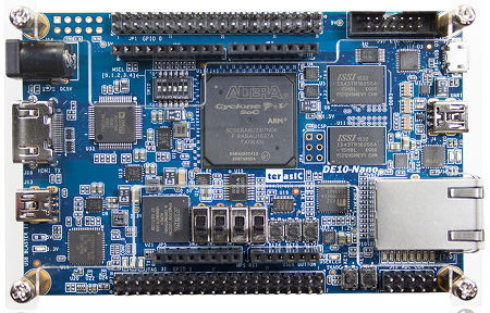
Building embedded Linux for the Terasic DE10-Nano (and other Cyclone V SoC FPGAs)
2017/08/20 Oguz Meteer // guztech
A little while ago, I bought a Terasic DE10-Nano FPGA development board. Of course I wanted to do some cool things with it, and a friend of mine found this nice embedded Linux beginners guide. The guide goes from using a Golden Hardware Reference Design (GHRD) and adding a custom IP, to developing a Linux kernel driver to use the custom IP. While some steps are explained in a lot of detail, other steps are a bit lacking because they expect the reader to have experience with how to create a Qsys component and such. That, combined with the fact that some pieces of software used in the guide are pretty old now, I have decided to create a step by step guide on building your own, fairly up-to-date embedded Linux and custom hardware with a kernel driver.
I will not go into details on subjects where the guide at RocketBoards.org already explain it very well. If you want to know more about a specific step, check their guide for more information. Also, I have marked important sections with “Attention:”.
Let’s get started!
Step 0 — Preparation
So you bought a Terasic DE10-Nano (or a similar Cyclone V SoC FPGA development board). Where do you first start? By installing the necessary tools of course. There are two pieces of software you need to download and install to follow this guide:
- Quartus Prime — This is the software suite that you use to create hardware designs. Any version will be sufficient, so I picked the Lite version which is free.
- Intel SoC FPGA Embedded Development Suite (EDS) — This software suite is used to develop software that will run on the ARM core(s) of the Cyclone V SoC. Again, any version will work and I downloaded the Standard edition.
The latest version of both software suites is 17.0 as of this writing. Quartus Prime also has a small update which you can download separately, or you can download a fully updated version. I did not have any version of Quartus Prime installed yet, so I downloaded the fully updated version.
Attention: I use Arch Linux, so some steps might be a little different if you are using Windows.
Step 0.1 — Installing Quartus Prime
First you need to install Quartus Prime. If you downloaded the Lite version, it will install in a folder called intelFPGA_lite, and the other versions will install in a folder called intelFPGA. Keep that in mind as you will need it in the next step.
Step 0.2 — Installing SoC EDS
Next you need to install SoC EDS in the same folder as where you installed Quartus Prime. By default, the installer will install in a folder called intelFPGA. So if you installed Quartus Prime Lite, then you will need to modify this to intelFPGA_lite. If you installed the Standard or Pro editions of Quartus Prime, then you do not need to modify anything.
Step 0.3 — Setting the MSEL switches
There are many ways that the Cyclone V SoC can be configured, and they can be selected using the MSEL switches. By default, the switches are set to On, Off, On, Off, On, On for switches 1 to 6 respectively.
Attention: for this guide they should all be on. If they are not all on, then the in later steps, the FPGA will not get programmed.
Step 1 — Creating and modifying the hardware design
Manufacturers of FPGA development boards usually supply reference designs so that users can get their boards up and running quickly. With Intel/Altera boards these are called the Golden Hardware Reference Design (GHRD). We will use a GHRD to create our own hardware design.
Step 1.1 — Getting the GHRD
Terasic, the manufacturer of the DE10-Nano board, also supplies GHRDs for their boards. For the DE10-Nano, you can download the “DE10-Nano CD-ROM” (aka SystemCD) that contains everything you need. If you have a different board with the Cyclone V SoC, then download the CD-ROM image for your board.
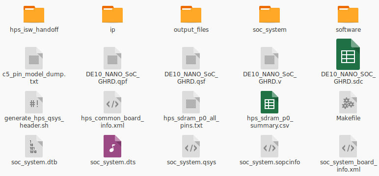
After you have downloaded the SystemCD zip file and extracted it, you can find several reference designs in the Demonstrations folder. The GHRD that we will use in this guide is located in Demonstrations/SoC_FPGA/DE10_NANO_SoC_GHRD. Once you are done with this guide and get everything up and running, I suggest you also play around with the other GHRDs.
Let’s take a look inside the DE10_NANO_SoC_GHRD folder:
Step 1.2 — Upgrading IP
Start up Quartus Prime and open the soc_system.qpf project file. In the top left corner of the Quartus window, you will be greeted with this:
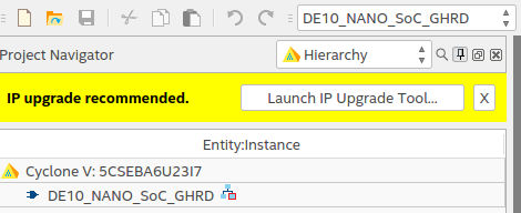
This GHRD was created with Quartus Prime version 16 whereas in this guide, I am using version 17. Click the Launch IP Upgrade Tool button, and this window will appear:
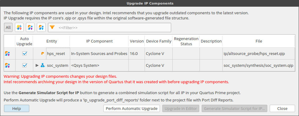
You can safely ignore the warning and click the Perform Automatic Upgrade button. After a little while, all of the used IP in the design will have been upgraded to latest version. Close the Upgrade Tool window.
Step 1.3 — Modifying the GHRD
We will modify the GHRD using the Qsys tool, which can be started from within Quartus Prime (Tools → Qsys). Once Qsys has started, open the soc_system.qsys project file. This is the hardware reference design that we will modify:
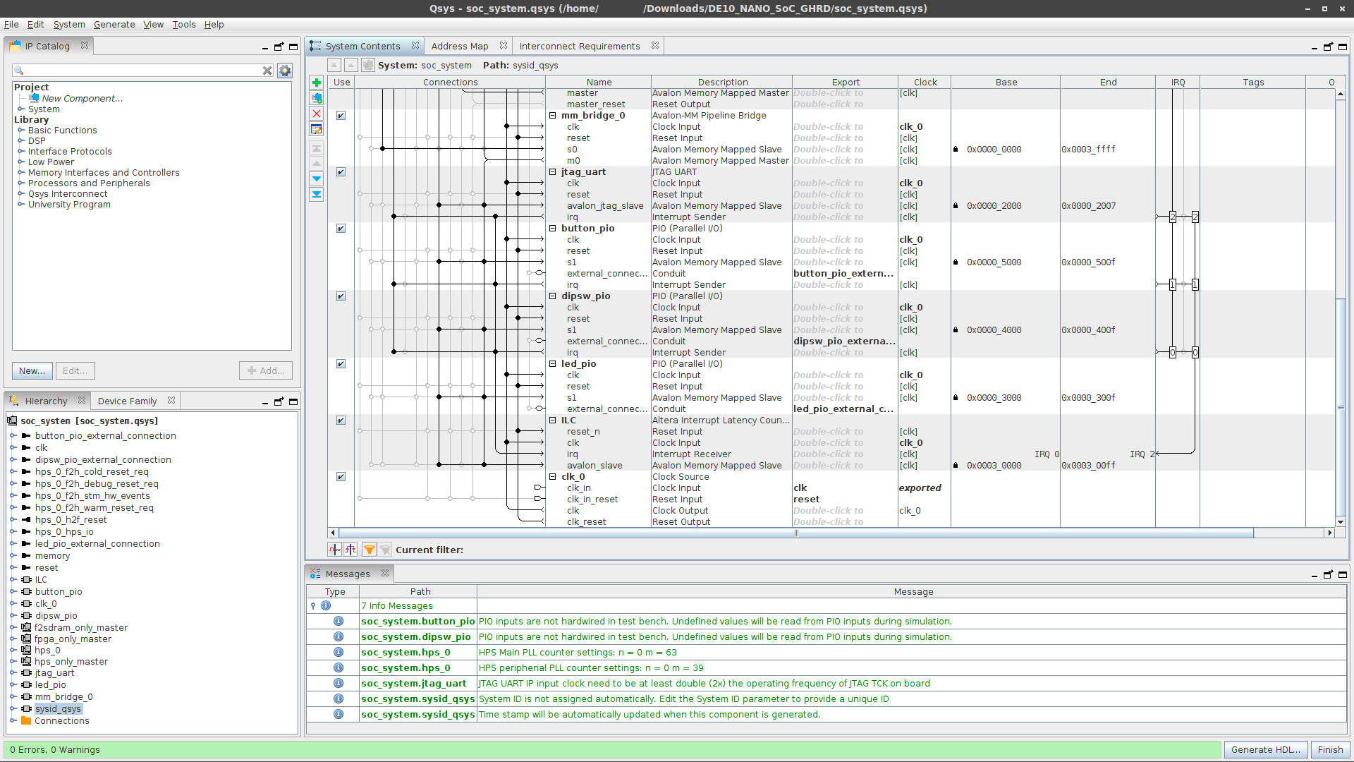
Like in the guide at Rocketboards.org, we will remove the led_pio IP and add our own custom IP. Right click on led_pio IP and click Remove.
Step 1.4 — Creating a custom IP
Adding custom hardware to a hardware design is a two step process. First we describe the custom IP using a hardware description language (HDL) such as VHDL and (System) Verilog, and then we create a Qsys component so that we can add our custom IP to the hardware design. Here we will use the same IP “code” that is used in the Rocketboards.org guide. This custom IP is an Avalon Memory Mapped Slave that acts as a GPIO peripheral. The output of this IP will be connected to the LEDs on our DE10-Nano so that we can modify which LEDs light up from Linux running on the ARM cores.
Create a folder custom_leds in DE10_NANO_SoC_GHRD/ip/, and create a file custom_leds.sv in the newly created DE10_NANO_SoC_GHRD/ip/custom_leds/ folder. Copy and paste the following code in the custom_leds.sv file:
Step 1.5 — Creating a custom component
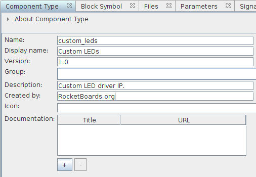
In order to use our custom_leds IP in Qsys, we need to create a Qsys component (File → New Component). This will open the Component Editor. In the Component Type tab we can enter information about the IP that we are creating. I entered the following information:
- Name: custom_leds
- Display name_:_ Custom LEDs
- Description: Custom LED driver IP.
- Created by: RocketBoards.org
Next, we go to the Files tab, and under the Synthesis Files section, we add our custom_leds.sv file so that Qsys and Quartus Prime know which hardware description to use when our component is being synthesized:
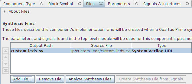
Normally, you can click the Analyze Synthesis Files button so that the editor can find the signals of your IP and add them to the component automatically. However, Qsys cannot analyze SystemVerilog files (which is the language used in the Rocketboards guide), so we have to do this step by hand. If your IP is described in VHDL or Verilog, then you could simply add the signals with a click of a button.
Go to the Signals & Interfaces tab, click on «add interface», and select Clock Input. Change the name of the clock interface from clock_sink to clock:
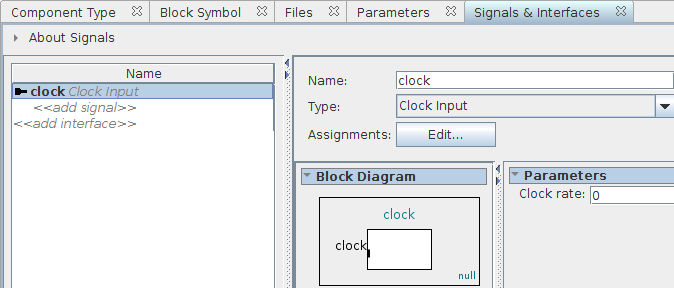
Click on «add signal» below our newly define clock interface, and select clk. Change the name of the signal from clock_clk to clk:
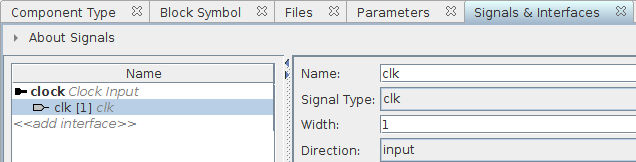
We rename the interface and especially the signals to make sure that they are the same as in our IP description. If we did not rename them, then we would have to change the IP description signal names.
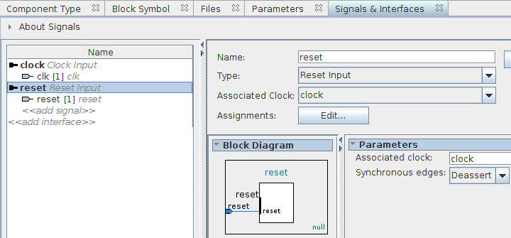
Next up we will add the reset signal to our component. Click on «add interface» and select Reset Input. Rename the interface from reset_sink to reset. Now click «add signal» and select reset. Rename the reset signal from reset_reset to reset:
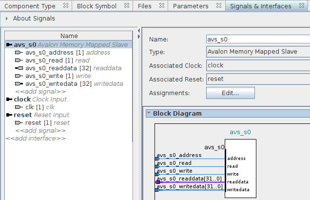
Now that we have defined the clock and reset signals of our component, we will define the Avalon Memory Mapped Slave interface and its associated signals. Click on «add interface» and select Avalon Memory Mapped Slave. Change the name of the interface from avalon_slave to avs_s0. Set Associated Clock to clock, and Associated Reset to reset.
Now add the following signals to the avs_s0 interface:
- Type: address — Name: avs_s0_address — Width: 1 — Direction: input
- Type: read — Name: avs_s0_read — Width: 1 — Direction: input
- Type: write — Name: avs_s0_write — Width: 1 — Direction: input
- Type: readdata — Name: avs_s0_readdata — Width: 32 — Direction: output
- Type: writedata — Name: avs_s0_writedata — Width: 32 — Direction: input
This should result in:
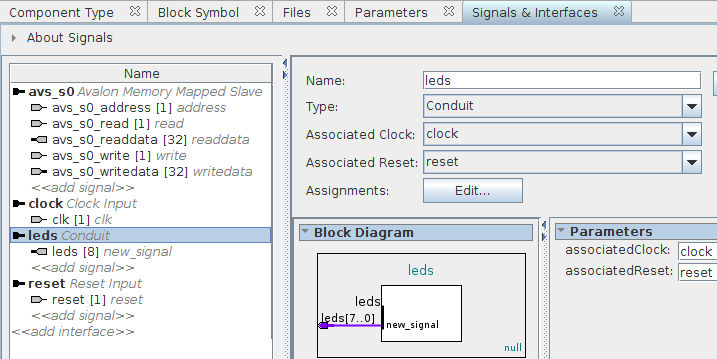
The last interface and signal that we have to add is for the leds output of our IP. Click «add interface» and select Conduit. Rename the interface from conduit_end to leds. Again, make sure that the associated clock and reset are set to clock and reset respectively. Finally click «add signal», select *, and name the signal leds. Set the signal width to 8 and make it an output. You should end up with this:
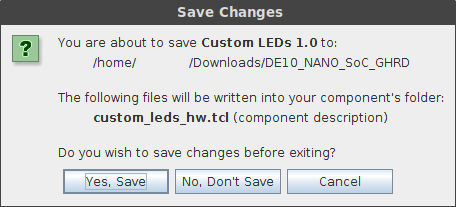
Make sure that the Messages section at the bottom does not report any errors, and click Finish to create our custom IP. A new window will appear, and you should answer it with Yes, Save:
There is one final step to creating our custom component. Later on, when preparing to configure and compile the Linux kernel, we will generate a Device Tree which tells the kernel what kind of hardware is present in our system. This can be used by the kernel to load drivers for example. To make sure that our custom component is correctly added to the Device Tree, we have to modify the custom_leds_hw.tcl file that Qsys generates when we saved our changes just now.
Open up the DE10_NANO_SoC_GHRD/custom_leds_hw.tcl file and append the following to it:
Remember this part, since we will be referring to it in step 4 of this guide.
Step 1.6 — Adding the custom component to the hardware design
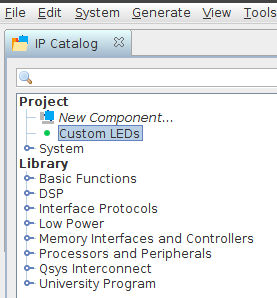
To add our custom component to the hardware design, double click on Custom LEDs under Project in the IP Catalog tag, and click Finish in the window that appears:
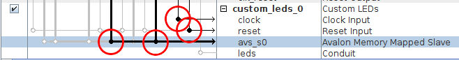
Now that we have added the custom component to our hardware design, we need to connect it to the rest of the system. Click on the four white empty dots marked with a red circle to connect the Avalon, clock, and reset interfaces:
The final step is to make a connection for the leds conduit output of our component. Right click on leds of our custom_leds_0 instance, and select Connections: custom_leds_0.leds → Export as: custom_leds_0_leds. This exports the leds output of our custom component as an external signal, not connected to the rest of the components of our hardware design. This makes sense, since we want to connect it to the LEDs on our board.
Step 1.7 — Generating HDL
First, save the hardware design in Qsys (Ctrl-S). Now it’s time to generate the HDL that describes the hardware design we created in Qsys. This generated HDL output will be used by Quartus Prime to actually synthesize the design, and create a bitstream which we can use to program the FPGA.
To do this, click on Generate → Generate HDL in Qsys_._ Click on Generate in the window that appears, and when the generation process is finished, click Close. Since we are done with Qsys, we can now close it.
Step 1.8 — Preparing synthesis
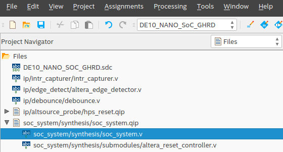
Go back to Quartus Prime, and double click on DE10_NANO_SoC_GHRD in the Project Navigator. This will open up the top-level file that describes our entire hardware design. We need to make a few changes because we removed the led_pio component and replaced with our own component.
In our top-level file called DE10_NANO_SoC_GHRD.v file, search for led_pio_external_connection_export and replace it with our own exported signal custom_leds_0_leds_new_signal. So we go from this:
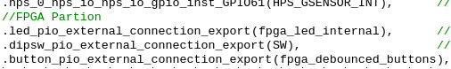
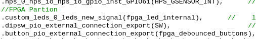
The final change is required because Qsys apparently instantiates our custom component incorrectly. Our component is named custom_leds but Qsys thinks it is new_component. In the Project Navigator, change Hierarchy to Files, and open the file soc_system/synthesis/soc_system.v:
Search for “new_component”:
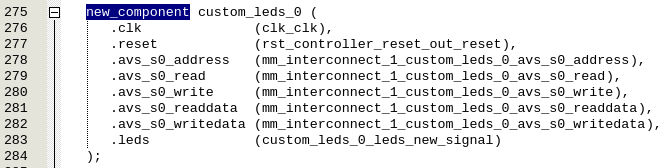
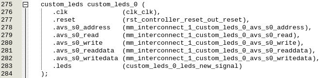
And replace it with “custom_leds”:
Step 1.9 — Synthesizing the system
We can finally synthesize the system and generate a bitstream. In Quartus, in the left panel, double click on Assembler (Generate programming files). This process should be done in about 5-10 minutes depending on your computer. When it’s done, we need to create a Raw Binary File. Click on File → Convert Programming Files, and follow these steps:
- For Programming file type select Raw Binary File (.rbf).
- For Mode select Passive Parallel x16.
- For File name, name the output file soc_system.rbf.
- In the Input files to convert section, click on SOF Data, and click on the Add File button on the right. Select the output_file/DE10_NANO_SoC_GHRD.sof file.
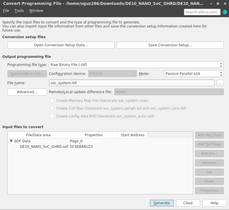
Click on Generate to generate the soc_system.rbf file. And with this, we are done with the hardware part of this guide.
Step 2 — Generating the preloader
Open up a terminal and execute embedded_command_shell.sh in your SoC EDS installation folder, which by default is
/intelFPGA_lite/17.0/embedded/ if you installed everything in the same folder as I recommended in steps 0.1 and 0.2 at the beginning of this guide. After executing that shell script, you now have access to several tools of SoC EDS which we will need in this and coming steps.
In your terminal, go to your DE10_NANO_SoC_GHRD folder and execute:
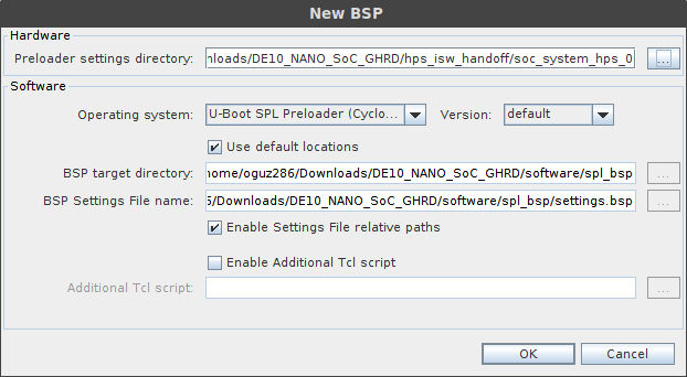
which will open up the BSP Editor. Clicking on File →New HPS BSP opens up the following window:
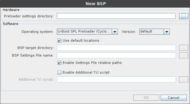
We have to select the correct Preloader settings directory by clicking on the “..“ button next to it and selecting the DE10_NANO_SoC_GHRD/hps_isw_handoff/soc_system_hps_0/ folder. The rest of the settings will get filled in for you, so just click OK:
Step 2.1 — Configuring the preloader
In the left panel, click on Common, and enable FAT_SUPPORT as shown in the screenshot below:
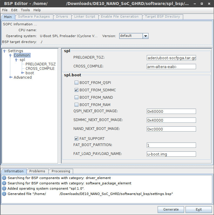
That is the only change we had to make, so click Generate button in the bottom right of the BSP Editor window. When it’s done, click Exit.
Step 2.2 — Compiling the preloader
The generated output of the BSP Editor can be found in the DE10_NANO_SoC_GHRD/software/spl_bsp/ folder. Also generated is a Makefile that we can use to compile the preloader. In your terminal, type:
And that is it for the preloader!
Step 3 — Setting up U-Boot
The next step is setting up U-Boot which is responsible for several things such as loading the bitstream into the FPGA and booting the Linux kernel. Assuming you are in the DE10_NANO_SoC_GHRD/software/spl_bsp/ folder, go back to the DE10_NANO_SoC_GHRD/software/ folder:
Step 3.1 — Getting and setting up the GCC toolchain
To compile U-Boot and the Linux kernel, we need a GCC toolchain for the ARMv7 instruction set. You can probably download one with your package manager, but since this step is different for each Linux distribution, we will simply download a toolchain from Linaro. While, as of this writing, the newest version of the Linaro GCC toolchain is 7.1.1-2017.05, it unfortunately throws errors when compiling the version of U-Boot that we will be using, which is somewhat old. So we will use the newest version that compiles U-Boot correctly, and that is version 6.3.1-2017.05 as of this writing. We will download the latest GCC 6.x version and unpack it in the DE10_NANO_SoC_GHRD/software/ folder:
(You can also go to that link in the snippet above, download it and extract it manually as well if you do not want to use the terminal)
Next we have to set the CROSS_COMPILE environment variable to point to our newly extracted GCC toolchain:
Attention: if you close the terminal after setting the CROSS_COMPILE environment variable, you have to set it again! To do that, just go to the DE10_NANO_SoC_GHRD/software/ folder and execute the code snippet above.
Step 3.2 — Getting and compiling U-Boot
Altera/Intel have their own version of U-Boot on the Altera opensource GitHub repository, which is modified to run specifically on their FPGAs. Let’s clone their repository:
We want to make sure that we do not use the code from the master branch that could potentially have bugs, so we will use the latest stable release version. To find all versions that Altera has released:
As of this writing that is rel_socfpga_v2013.01.01_17.08.01_pr, so that is the version that we will use:
To make sure that we start with a clean slate before compiling, we will clean the U-Boot folder:
And then we will compile U-Boot:
This produces the u-boot.img U-Boot image file in the same folder.
Step 3.3 — Setting up the boot script
U-Boot needs a boot script to know how to setup the FPGA and load the Linux kernel. Create a file named boot.script in the DE10_NANO_SoC_GHRD/software/ folder with the following contents:
Read the Rocketboard.org guide for more information on what this boot script does. Now that we have a boot script, we need to compile it so that U-Boot can use it:
That creates the compiled boot script file u-boot.scr, and with that, we are done with U-Boot!
Step 4 — Generating and compiling the device tree
This guide will not into detail what the device tree is and what it is used for, because the guide at Rocketboards.org does an excellent job explaining it. The SoC EDS tool that we installed contains an application called sopc2dts that takes a .sopcinfo file and optional .xml board files, and generates a .dts file, which is the source version of our device tree. If we did not have this tool, then we would have to create a .dts file by hand which can be very tedious. There are two .xml board files that are in the GHRD: hps_common_board_info.xml and soc_system_board.info.xml. These files are for external peripherals that you can connect to the HPS (ARM cores) part of the system, but since Qsys does not know about peripherals that lie outside the FPGA fabric, they are described in those two .xml board files. The hps_common_board_info.xml file contains pointers to the led_pio component that we removed and replaced with the custom_leds component in steps 1.3 and 1.4 respectively, so we have to modify it for the sopc2dts application to generate a correct and valid .dts file.
Open up hps_common_board_info.xml and replace all “led_pio” with “custom_leds_0” (which is the name of our instantiated custom_leds component as you can see in the image in step 1.6). We now have to compile this .dts file to obtain a .dtb binary device tree file. To do all of this, execute the following in the same terminal you have been using up till now (if you did everything correctly, you should still be in the DE10_NANO_SoC_GHRD/software/ folder before executing the following snippet):
This generates the .dts file. Execute the following to compile it:
Do you remember that at the end of step 1.5 we added several lines to the DE10_NANO_SoC_GHRD/custom_leds_hw.tcl file? This is what we added back then:
Because we did that, the .dts file now contains the following section:
If we had not added it back then, we would have had to add it manually to our .dts file each time we made a change to our system. So remember to add the module assignment commands to the .tcl file of each component you create, so that you do not have to remember to add it manually every time you build a new system.
Step 5 — Testing the system
We are now at a point where we are able to test if we did everything correctly up till this point by preparing an micro SD card with the preloader, U-Boot, the raw bitstream file, and the compiled device tree file on it. We will create an image file on the computer, create three partitions on it, copy the files to the image, and then copy the image to an actual micro SD card. Pay close attention to the commands because when used incorrectly, you can wipe out your host system.
Step 5.1 — Creating an image file and mounting it
First we create a 512 MiB file on our computer that will be our image (you should be in the DE10_NANO_SoC_GHRD folder if you followed the guide correctly):
We will mount this file as if it was an actual disk so that we can use the usual tools to manipulate disks:
The output of this command is the name of the loopback device that we can use to manipulate the image file. On my machine, the output is:
On your machine it may be something else, so remember what it is, because we will need it in the next step.
Step 5.2 — Creating partitions
We will be using fdisk to create three partitions: a FAT partition of 256 MiB, the root file system of type ext4 and size 254 MiB, and a 1 MiB partition of type A2 (Altera custom). This leaves 1 MiB of free space that will be used by the Master Boot Record. Let’s start fdisk so that we can create these partitions (remember to replace /dev/loop0 with wherever the SD card image was mounted on your system):
We can view the current partitions on a device with the “p” command. In our case, we have a new device so there should be no partitions. Verify this by typing p and Enter:
First we will create the A2 (Altera custom) partition with a size of 1 MiB with the “n” (new) command. It will be a primary partition with partition number 3, default first sector, and a size of 1 MiB. This can be done by entering the following commands:
So we enter “n”, “p”, “3”, *blank*, and “+1M”. fdisk tells us that it created a new partition 3 of type ‘Linux’ of size 1 MiB. As we can see, the type is ‘Linux’ which is the default partition type, and we have to change it to A2 (Altera custom). Changing the type of a partition can be done with the “t” command:
Next up is the root file system, which is also a primary partition with partition number 2, default first sector of 4096, and a size of 254 MiB:
The type is again ‘Linux’ which is correct so we do not have to change it. Finally, we will create the 256 MiB, primary partition of type FAT with partition number 1, and default first and last sectors:
We will change the type of partition 1 to FAT:
Verify that all partitions were created correctly:
Finally, we will write the changes we have made to the “device” with the “w” command:
As we can see, re-reading the partition table has failed which means the our host system is not aware of the new partitions that we just added to our mounted loop device. We can fix this with partprobe command (remember to replace /dev/loop0 with wherever the SD card image was mounted on your system):
Verify that the our host system now knows about the three partitions we created:
As you might have guessed, /dev/loop0p1, /dev/loop0p2, and /dev/loop0p3 correspond to the three partitions we created.
Step 5.3 — Creating the file systems
Now that we have the partitions setup, we need to create the appropriate file systems on the partitions, and copy over the files that we generated in previous steps. First off is the preloader image that will be copied to the A2 partition which is partition number 3 (remember to replace /dev/loop0 with wherever the SD card image was mounted on your system):
We did not create a file system for the A2 partition since the A2 partition type is a raw partition and the preloader is a raw binary file. However, both the FAT, and ext4 root file system partitions require file systems to be created though. Create both file systems using the following two commands:
The files required to boot the Cyclone 5 SoC need to be copied to the FAT partition, so first we need to mount it:
Copy the U-Boot image, compiled boot script, device tree binary, and the FPGA raw bitstream files to the newly mounted partition:
Finally, make sure that all files have been actually copied to the partition, and then unmount the FAT partition:
Step 5.4 — Write the SD card image to an actual SD card
Find out which device is your SD card by executing lsblk:
The SD card in the SD card reader in my computer is the mmcblk0 device, so to write the SD card image file that we prepared to the SD card, execute the following:
Once this is done, you can unmount the SD card and plug it into the DE10-Nano board.
Step 5.5 — Testing the system
Find out which device is the USB UART that is connected to the UART port of the DE10-Nano:
Then use your favorite terminal emulator (like minicom) and connect to the DE10-Nano:
Now plug in the power to the DE10-Nano and you should see something like this:
We can see that the Preloader sets up the clocks to different peripherals on the board, enables SDRAM, and then starts U-Boot. U-Boot then will read the raw bitstream file and load it into the FPGA. You can verify if the bitstream was loaded correctly by looking at the LEDs on the board. There should be one blinking LED. U-Boot also reads the device tree file, and finally also tries to read the Linux kernel (zImage), but it cannot find it. This of course makes sense, since we have not compiled it yet, so let’s do that now.
Step 6 — Configuring and compiling the Linux kernel
Before preparing the Linux kernel, I want to note that we used the latest GCC 6.x version to compile U-Boot. We can also use the same version to compile the rest of the software which are the Linux kernel and Buildroot, but we can also use the latest version of the Linaro GCC 7.x toolchain to compile them. If you want to use GCC 6.x then you skip the guide to step 6.2, and if you want to use GCC 7.x then continue with the next step.
Step 6.1 — Getting and setting up the GCC 7.x toolchain
Follow this step if you want to use the latest version of GCC (7.x as of this writing) to compile the rest of the software. We will again use the Linaro GCC toolchain. If you followed the guide up till this point, you should be in the DE10_NANO_SoC_GHRD/ folder, so in your terminal that you should still have open, execute the following:
This should look familiar to you by now. Do not forget to export the CROSS_COMPILE environment variable if you happen to close the terminal.
Step 6.2 — Getting the Linux kernel source code
Make sure that you are in the DE10_NANO_SoC_GHRD/software/ folder. Altera has a fork of the Linux kernel on their Github, so let’s get it from there: A reader told me that the fork on Github does not contain the versions used for this tutorial anymore. I have uploaded a local copy to Gitlab:
To find all the versions that are available:
As of this writing, the newest version is rel_socfpga_4.11_17.08.02_pr, so that is the version that we will be using:
Step 6.3 — Configuring the Linux kernel
I have mentioned this a couple of time before, but make sure that the CROSS_COMPILE environment variable has been set and is pointing to the correct version of the GCC toolchain, because we cannot configure nor compile the Linux kernel if is is not set. First let’s create a default configuration:
We are now ready to configure the Linux kernel:
You should be greeted with the following:
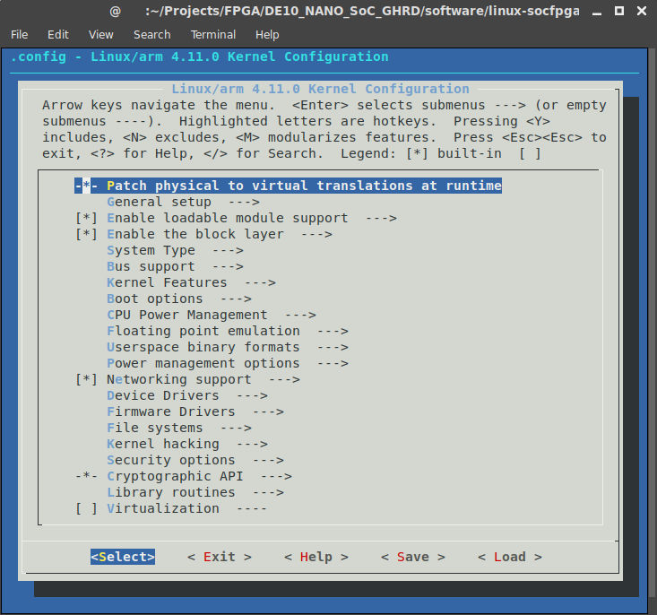
There are many options that you can modify and they lie outside the scope of this guide. For more information about an option, just enter “?” when hovering over that option. Although the default settings are pretty much ok, we still need to make two changes.
First go to General setup and uncheck Automatically append version information to the version string option. Whenever the kernel loads a module, it checks if the version the module is the same as the kernel version, and rejects loading if they differ. If we uncheck this option, it makes development easier since we can test different versions of drivers. For production systems, leaving this option checked is recommended though.
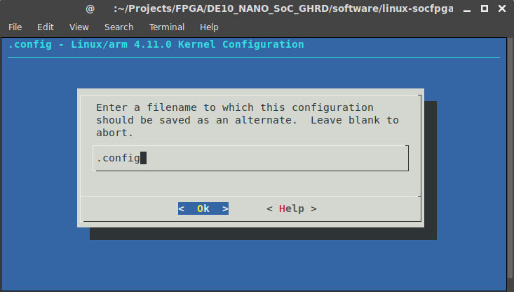
The second change we will make can be found in Enable the block layer and is called Support for large (2TB+) block devices and files. This option should be turned on, and is needed if we want to use ext4 file systems with full read/write support. If this option is disabled, then we can only mount ext4 file systems in read-only mode. Press ESC until you are back on the main page, and press the right arrow key until you have selected Save, and then press Enter to save these settings. The default filename “.config” is fine, so select Ok to save our settings. We are done, so select Exit.
Step 6.4 — Compiling the kernel
To compile the kernel just execute the following:
Once this is done, we will have a zImage file which is a compressed Linux kernel image.
Step 7 — Generating a root file system
As I have mentioned several times before, the guide at RocketBoards.org has much more background information on what the Linux kernel expects from a root file system, so definitely check it out. We will use Buildroot, which is a collection of tools that automate the process of creating a root file system and all the necessary system applications. Since we were in the DE10_NANO_SoC_GHRD/software/__linux_socfpga/ folder, execute the following:
Search the tags to find all versions:
Normally, I use the latest stable version which is 2017.05.2 as of this writing. However, if you are using GCC 7.1.1, then you need a newer version (2017.08-rc2 as of this writing). So depending on the version of the compiler you decided to use, check one of them out:
Step 7.1 — Configuring Buildroot
The command to configure Buildroot requires the path to the GCC toolchain that we downloaded before. Depending on whether you chose to use GCC 6.3.1 or 7.1.1, execute the following:
You should be greeted with the following:
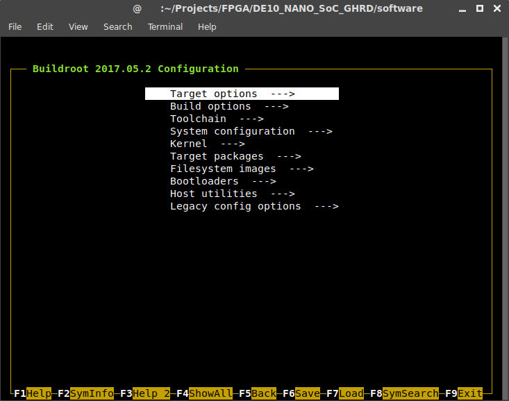
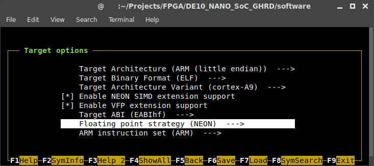
Here is a list of changes we need to make under Target options:
- Target Architecture: ARM (little endian)
- Target Architecture Variant: cortex-A9
- Enable NEON SIMD extension support (NEW): Enable
- Enable VFP extension support (NEW): Enable
- Target ABI: EABIhf
- Floating point strategy: NEON
Next up is the Toolchain section. For GCC version, select the version that you are using, and kernel headers series should be 4.6.x and 4.10.x for GCC version 6.3.1 and 7.1.1 respectively. Since I’m using GCC 7.1.1, I have configured it like this:
- Toolchain type: External toolchain
- Toolchain: Custom toolchain
- Toolchain prefix: arm-linux-gnueabihf
- External toolchain gcc version: 7.x
- External toolchain kernel headers series: 4.10.x
- External toolchain C library: glibc/eglibc
- Copy gdb server to the Target (NEW): Enable
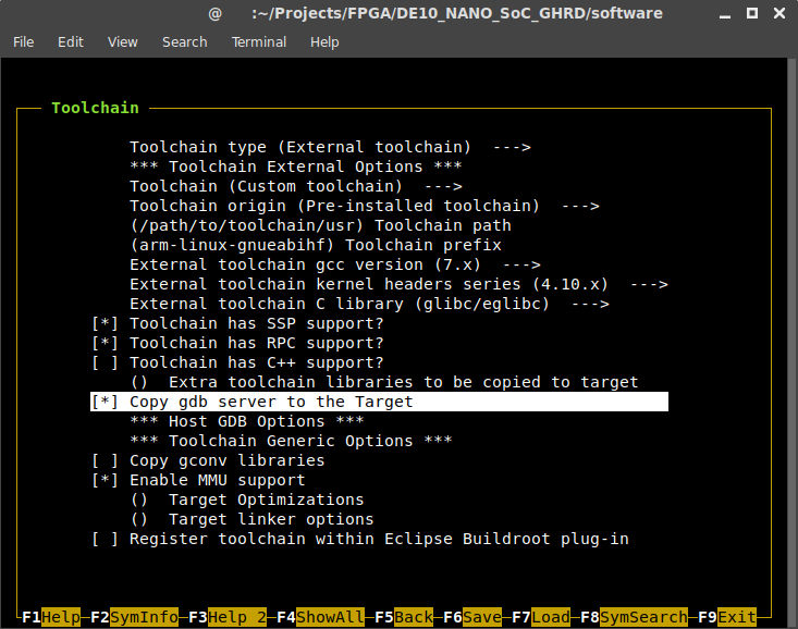
While these are the only necessary changes, there are still a ton of options that you can adjust if you want to. Perhaps the most important is to change the root password (System configuration →Root password). You can also let Buildroot add all kinds of extra applications to you root file system. I will stick with the default settings in this guide. To save the configuration, press F6 and Enter to accept the default file name. Press F9 to exit the application.
Step 7.2 — Configuring BusyBox
Before we move on, we need to configure BusyBox. In order to do that, we need to make sure that we have the cpio and rsync packages installed on our host system. Then execute:
You will be greeted with the following:
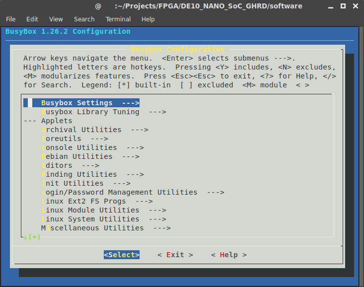
Luckily, the default settings are ok, so simply go to Exit. It will ask you if you want to save your new configuration, and since we do want to do that, answer Yes.
Step 7.3 — Generating the root file system
There is one last command that we have to execute to generate the root file system. Depending on which version of GCC you are using:
Step 8 — Testing the system again
We are ready to copy everything over to the SD card again. Remember that we have three partitions on the SD card that we prepared before:
- 256MB FAT
- 254MB ext4
- 1MB Altera custom
The 1MB partition will not be modified anymore, so only the first two partitions need our attention. When you plug in the SD card, we need to know where the FAT and ext4 partitions are mounted. To find this, you can use the lsblk command like we did before in step 5.4. Now that we know where the two partitions have been mounted, we will first copy over the Linux kernel to the 256MB FAT partition which should contain the soc_system.dtb, soc_system.rbf, u-boot.img, and u-boot.scr files:
And finally, we copy over the root file system to the 254MB ext4 partition and wait for it finish copying to the SD card:
Unmount the partitions and unplug the SD card, and plug it in the DE10-Nano board. When you power up the board, you should see Linux starting up and show you a login prompt. You can login as root with a blank password. If you configured a root password during the Buildroot configuration step, then of course use that password.
You have now successfully set up your own embedded Linux. Next up is using the custom_leds IP to drive the leds with a user-space application, and a kernel module.
Step 9 — Driving the LEDs with a user-space application
To be able to access our custom_leds IP, we need to know to which address it is mapped, and ask the kernel to give us a pointer that maps it to the IP so that we can access it. Going in to detail on how memory mapping works in Linux would be way out of the scope of this guide, but the guide at RocketBoards.org has some good links that explain this process very well. Luckily there is a tool that SoC EDS provides which creates a header file with all the addresses in it. This makes it easier to access any peripheral in the system, not just our custom IP. While still being in the DE10_NANO_SoC_GHRD/software/ folder, execute the following:
This will create a single header file called hps_0.h based on the .sopcinfo file. Now create a file devmem_demo.c in the userspace folder that we just created, and put the following code in it:
Also create a file called Makefile (no extension) with the following content:
Both these files are from the guide at RocketBoard.org and they explain in detail what the code does, so I will not repeat it here. Again, make sure that you have the CROSS_COMPILE environment variable set! To compile our user-space application, execute the following:
Now we can copy our executable to the SD card. Plug the SD card into your host computer and execute the following:
Unmount the card and plug it in to the DE10-Nano. Log in to the system, and execute the following:
and you should see the LEDs blink 10 times. You now have a user-space application that can talk to the custom_leds IP.
Step 10 — Driving the LEDs with a kernel module
Another way of driving the custom_leds IP is to write a kernel module for it, and let user-space applications use the kernel module to access it. For more information on how kernel modules work, check the guide at RocketBoards.org. First, create a folder kernelspace in DE10_NANO_SoC_GHRD/software/:
cd .. mkdir kernelspace cd kernelspace
Then create a file custom_leds.c in it with the following contents:
This the code for the kernel module as is also used in the RocketBoards.org guide. To compile a kernel module, you need to use the build system included in the Linux kernel you want to compile it for. In our case, the kernel module will be built using the Linux kernel in the DE10_NANO_SoC_GHRD/software/linux-socfpga/ folder. To do this, create a file called Makefile with the following contents:
And finally, create a file called Kbuild with the following contents:
Make sure that the CROSS_COMPILE environment variable is set, and execute:
This will build the kernel module, and the output is the custom_leds.ko file. Plug the SD card in to your host system, and copy the file over to the SD card:
Unmount the SD card, plug it into the DE10-Nano, and power it up. After you have logged in, load the kernel module:
If you see those messages, then the kernel module was loaded successfully. This should have also created the file /dev/custom_leds, which you use to communicate with the kernel module. You can change which LEDs light up by sending values to this file:
If you want to unload the kernel module:
All of the LEDs should turn off and the /dev/custom_leds file is gone.
Final words
There you have it, you have created a custom embedded Linux, a custom IP, created a user-space application and a kernel module to use the custom IP! If you find anything wrong in the guide, you can contact us on Twitter @BitlogIT
Источник


