- Install Redhat/CentOS Operating System on UCS M-Series Server
- Available Languages
- Download Options
- Contents
- Introduction
- Prerequisites
- Requirements
- Components Used
- Background Information
- Download Required Driver ISO Bundle
- Steps to install RHEL 7.0 or CentOS 7.0
- Verify
- Steps to install RHEL 6.5 or CentOS 6.5
- Verify
- Post Installation Verification
- heatzync / HOWTO.md
- Cisco UCS Integrated Infrastructure with Red Hat Enterprise Linux OpenStack Platform and Red Hat Ceph Storage (Design Guide)
- Available Languages
- Download Options
- Cisco UCS Integrated Infrastructure with Red Hat Enterprise Linux OpenStack Platform and Red Hat Ceph Storage
- Design Guide
- About Cisco Validated Designs
- Executive Summary
- Solution Overview
- Introduction
- Audience
- Purpose of the document
- Solution Summary
- Technology Overview
- Cisco Unified Computing System
- Comprehensive Management
- Radical Simplification
- High Performance
- Cisco UCS Manager
- Cisco UCS Fabric Interconnects
- Cisco UCS 5108 Blade Server Chassis
- Cisco UCS B200M4 Blade Server
- Cisco UCS C240M4 Rack Server
- Cisco UCS Fabric Extenders
- Cisco UCS IO Adapters
- Cisco UCS Differentiators
- Red Hat Enterprise Linux OpenStack Platform Architecture
- Red Hat Enterprise Linux OpenStack Platform 7 (Kilo) Services
- Third-party Components
- Red Hat Ceph Storage
- Storage Cluster Architecture
- Ceph Client Architecture
- RedHat Enterprise Linux OpenStack Platform 7 director
- Ready State Provisioning and Server Roles
- Network Isolation
- High Availability
- Cluster Manager and Proxy Server
- Cluster Services and Quorum
- Cluster Modes for Core Services
- Cluster Modes for Supporting Services
- Compute Node Clustering
- Ceph Storage Integration
- OpenStack Networking ML2 Core
- Cisco UCS Plugins
- Cisco Nexus 1000V Plugin
- Cisco Nexus Plugin
- Cisco UCS Manager Plugin
- Cisco Nexus 9000 Switches
- Solution Design
- Architectural Overview
- Cisco UCS B200 M4 Blade Server
- Cisco UCS C240 M4 Rack Servers
- Cisco UCS Fabric Interconnects and Cisco Nexus Switches
- IO Modules
- Recommended Configuration
- System Hardware and Software Specifications
Install Redhat/CentOS Operating System on UCS M-Series Server
Available Languages
Download Options
Contents
Introduction
This document describes how to install Redhat Enterprise Linux ( RHEL ) or CentOS Linux on the Cisco Unified Computing System (UCS) M-Series server using local storage.
Prerequisites
Requirements
Cisco recommends that you have knowledge of these topics:
- Cisco UCS Manager 2.5 or 3.1 version
- Storage Profiles
- Linux Operating Systems (OS)
Components Used
The information in this document is based on UCS M-Series.
The information in this document was created from the devices in a specific lab environment. All of the devices used in this document started with a cleared (default) configuration. If your network is live, make sure that you understand the potential impact of any command.
Background Information
Cisco M-Series modular server is one of the Cisco products that represents Composable Infrastructure design. The modular servers do not have a local storage but a centralized storage that can be shared by all servers. To access the shared storage, OS requires new Small Computer System Interface (SCSI) driver called as storage Network Interface Card ( sNIC ) and has to be added during installation for OS to detect the disks.
The next few sections of this document provides information on how to download the driver and install it during the OS installation.
Download Required Driver ISO Bundle
The UCS Hardware and Software Interoperability Matrix outlines the driver versions that are required for a particular OS, device, and firmware combination.These links for the Matrix Utility Tool and the Matrix PDFs, determines the required driver version.
Complete these steps in order to download the driver bundle:
- In a web browser, navigate to http://www.cisco.com.
- Under Support, navigate to Downloads > All Downloads.
- Click Servers — Unified Computing.
- Choose UCS M-Series Modular Server Software
- Click Unified Computing System (UCS) Drivers.
- Select the bundle you want to download, and click Download Now.
Steps to install RHEL 7.0 or CentOS 7.0
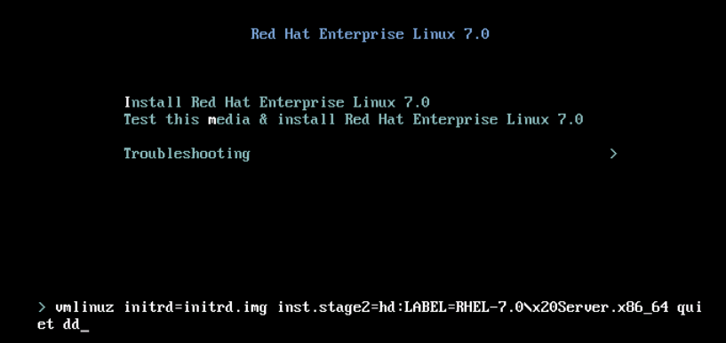
It is assumed that the user has powered up the server and is configured to boot from OS installation ISO image.
Step 1. At the first screen of OS installation wizard, highlight Install Redhat Enterprise Linux 7.0 option and press Tab key to view/add additional boot parameters of the installer. Add dd keyword at the end and click Enter key as shown in the image.
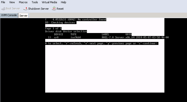
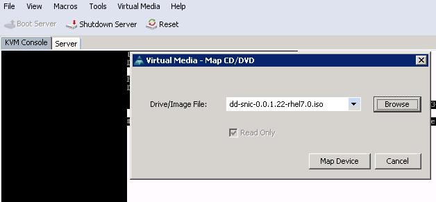
Step 2. The installer takes you to identify the source of driver disk (dd) file, as shown in the image. In this step, unmap the OS installation image and map the sNIC driver disk ISO file.
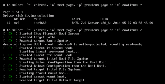
Step 3. Press r to rescan the media and select 1. It enlists the sNIC driver RPM file included in the driver disk ISO. Select 1 to include the driver and press c to load the driver, as shown in the image.
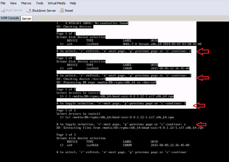
Step 4. Once the driver is extracted to memory space, unmap the driver disk ISO and map the OS installation ISO file. Press r to rescan it and press c to proceed with OS installation wizard, as shown in the image.
Verify
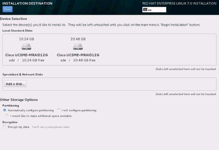
Once you proceed with the OS installation wizard, the Logical Unit Numbers (LUNs) created on the centralized shared storage via storage profile policy is detected by OS with the help of sNIC driver.
Steps to install RHEL 6.5 or CentOS 6.5
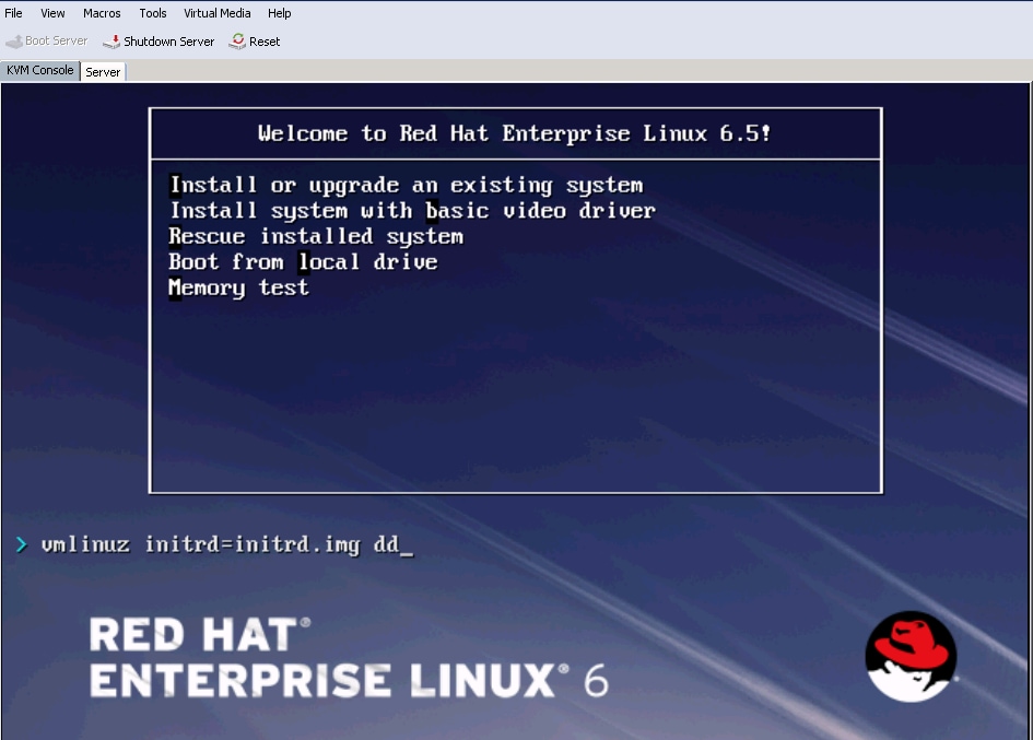
Step 1. From the welcome screen of the OS installation wizard, highlight Install or upgrade an existing system option and press Tab key to view/edit boot parameters. At the end of the line, add dd keyword and click on Enter key.
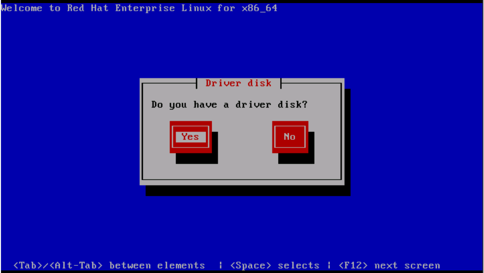
Step 2. OS installation wizard prompts for driver disk. Click Yes, as shown in the image.
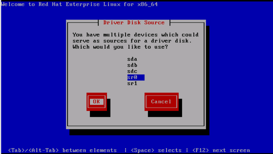
Step 3. As shown in the image, select option sr0 as the driver source location.
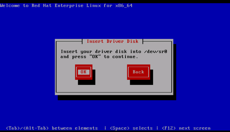
Step 4. Unmap OS installation ISO and map the sNIC driver disk ISO for RHEL 6.5 . After mapping the driver disk ISO, click OK, as shown in the image.
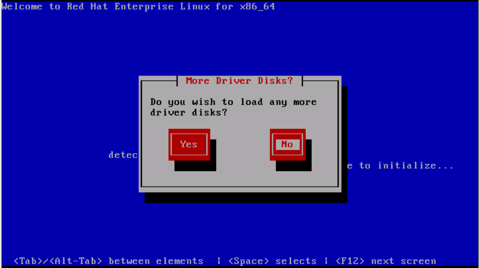
Step 5. OS extracts the sNIC driver and prompt for loading additional drivers during the installation.Click on No, as shown in the image and unmap the driver disk ISO file. Map the OS installation ISO image and continue with OS installation.
Verify
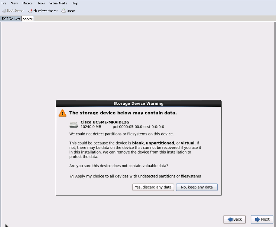
If the sNIC driver is loaded, OS will be able to detect the shared storage LUN as shown in the image.
Post Installation Verification
These OS commands enlists the sNIC driver details,
Источник
heatzync / HOWTO.md
HOWTO connect to a company’s VPN using the Cisco VPN client on linux
This HOWTO explains connecting to a VPN gateway over IPSec in «cert auth mode» utilizing the Cisco VPN client. The «cert auth mode» refers to the terms used in the vpnc man page, i.e. server + client certificates. The «cert auth mode» has not been implemented for vpnc, otherwise we would just use vpnc and avoid the headache that follows. openconnect is another alternative, but it does not support IPSec, only HTTPS/SSL. This HOWTO is written with the aim to provide a single document to describe all the steps required, instead of having to search many different things on the Internet.
This HOWTO was written from the perspective of an openSUSE 12.1 user, running a 3.1.10-1.9-desktop x86_64 kernel. The author does not claim to be an expert on any terms used, so if you find a mistake then please submit a patch.
Get the certificate provided by CompanyA
The company we are trying to connect to should provide us with some sort of a certificate, e.g. certificate.pfx. This type of certificate is a PKCS12 certificate which bundles the CA certificate for server authentication, the client/user certificate as well as the primary key. Save it somewhere on disk, e.g.:
Install and prepare kernel-source for our linux distro
In order to «compile» (Cisco calls it «install») the Cisco IPSec kernel module (see later section) we need the kernel sources for our distro. In openSUSE 12.1 do the following:
Make sure the version that will be installed is the same as the version we are currently running:
When the kernel-source has been installed, execute the following as root:
Download, patch and install Cisco VPN client
Now that the kernel-source has been installed we can download, patch and install the Cisco VPN client with the following steps (as root):
Remember to specify the kernel-source directory as /usr/src/linux- .
The module will be installed to /lib/modules/ /CiscoVPN/cisco_ipsec.ko.
Start the Cisco VPN daemon
The Cisco VPN client installation suggests starting the vpncclient_init service, so do it:
If we get errors such as:
then (1) we compiled/linked the module with the wrong kernel-source or (2) we forgot to symlink the Module.symvers file. We will have to repeat some of the steps above.
Import provided certificate for use with Cisco VPN client
The provided PKCS12 certificate should now be imported. The following commands can be used (as root):
Supply the certificate filename, e.g. /tmp/certificate.pfx as well as the password with which the certificate is locked/encrypted. Next, enter a password that we will easily remember.
View the imported certificate:
and provide the number of the corresponding certificate when asked. The certificate information will be displayed. Take note of the «Subject» and «Serial #» fields as they will be required in the next step.
Configure Cisco VPN client
Configure a profile for connecting to CompanyA. Let’s call the profile «CompanyA». As root:
and change the following properties as follows:
The moment of truth has arrived. To connect to the VPN of CompanyA, simply execute:
assuming /usr/local/bin is in our PATH.
When prompted, provide the certificate password we chose in a previous step as well as our unique username and password that should also have been provided by CompanyA. We should now be connected.
Источник
Cisco UCS Integrated Infrastructure with Red Hat Enterprise Linux OpenStack Platform and Red Hat Ceph Storage (Design Guide)
Available Languages
Download Options

Cisco UCS Integrated Infrastructure with Red Hat Enterprise Linux OpenStack Platform and Red Hat Ceph Storage
Design Guide
NOTE: Works with document’s Advanced Properties “First Published” property. Click File | Properties | Advanced Properties | Custom.
Last Updated: March 30, 2016
NOTE: Works with document’s Advanced Properties “Last Updated” property. Click File | Properties | Advanced Properties | Custom.

About Cisco Validated Designs
The CVD program consists of systems and solutions designed, tested, and documented to facilitate faster, more reliable, and more predictable customer deployments. For more information visit
ALL DESIGNS, SPECIFICATIONS, STATEMENTS, INFORMATION, AND RECOMMENDATIONS (COLLECTIVELY, «DESIGNS») IN THIS MANUAL ARE PRESENTED «AS IS,» WITH ALL FAULTS. CISCO AND ITS SUPPLIERS DISCLAIM ALL WARRANTIES, INCLUDING, WITHOUT LIMITATION, THE WARRANTY OF MERCHANTABILITY, FITNESS FOR A PARTICULAR PURPOSE AND NONINFRINGEMENT OR ARISING FROM A COURSE OF DEALING, USAGE, OR TRADE PRACTICE. IN NO EVENT SHALL CISCO OR ITS SUPPLIERS BE LIABLE FOR ANY INDIRECT, SPECIAL, CONSEQUENTIAL, OR INCIDENTAL DAMAGES, INCLUDING, WITHOUT LIMITATION, LOST PROFITS OR LOSS OR DAMAGE TO DATA ARISING OUT OF THE USE OR INABILITY TO USE THE DESIGNS, EVEN IF CISCO OR ITS SUPPLIERS HAVE BEEN ADVISED OF THE POSSIBILITY OF SUCH DAMAGES.
THE DESIGNS ARE SUBJECT TO CHANGE WITHOUT NOTICE. USERS ARE SOLELY RESPONSIBLE FOR THEIR APPLICATION OF THE DESIGNS. THE DESIGNS DO NOT CONSTITUTE THE TECHNICAL OR OTHER PROFESSIONAL ADVICE OF CISCO, ITS SUPPLIERS OR PARTNERS. USERS SHOULD CONSULT THEIR OWN TECHNICAL ADVISORS BEFORE IMPLEMENTING THE DESIGNS. RESULTS MAY VARY DEPENDING ON FACTORS NOT TESTED BY CISCO.
CCDE, CCENT, Cisco Eos, Cisco Lumin, Cisco Nexus, Cisco StadiumVision, Cisco TelePresence, Cisco WebEx, the Cisco logo, DCE, and Welcome to the Human Network are trademarks; Changing the Way We Work, Live, Play, and Learn and Cisco Store are service marks; and Access Registrar, Aironet, AsyncOS, Bringing the Meeting To You, Catalyst, CCDA, CCDP, CCIE, CCIP, CCNA, CCNP, CCSP, CCVP, Cisco, the Cisco Certified Internetwork Expert logo, Cisco IOS, Cisco Press, Cisco Systems, Cisco Systems Capital, the Cisco Systems logo, Cisco Unity, Collaboration Without Limitation, EtherFast, EtherSwitch, Event Center, Fast Step, Follow Me Browsing, FormShare, GigaDrive, HomeLink, Internet Quotient, IOS, iPhone, iQuick Study, IronPort, the IronPort logo, LightStream, Linksys, MediaTone, MeetingPlace, MeetingPlace Chime Sound, MGX, Networkers, Networking Academy, Network Registrar, PCNow, PIX, PowerPanels, ProConnect, ScriptShare, SenderBase, SMARTnet, Spectrum Expert, StackWise, The Fastest Way to Increase Your Internet Quotient, TransPath, WebEx, and the WebEx logo are registered trademarks of Cisco Systems, Inc. and/or its affiliates in the United States and certain other countries.
All other trademarks mentioned in this document or website are the property of their respective owners. The use of the word partner does not imply a partnership relationship between Cisco and any other company. (0809R)
© 2016 Cisco Systems, Inc. All rights reserved.
Table of Contents
Executive Summary
Cisco Validated Design program consists of systems and solutions that are designed, tested, and documented to facilitate and improve customer deployments. These designs incorporate a wide range of technologies and products into a portfolio of solutions that have been developed to address the business needs of our customers.
The purpose of this document is to describe the design framework used to deploy Red Hat Enterprise Linux OpenStack Platform 7 on a converged stack of Cisco UCS blade and rack servers. The Cisco Unified Computing System provides the compute, network, and storage access components of the cluster, deployed as a single cohesive system. Red Hat Enterprise Linux OpenStack Platform director is a toolset for installing and managing a complete OpenStack environment. The document describes Red Hat Enterprise Linux OpenStack design on Cisco Unified Computing system (UCS).
With the growing interest, continuous evolution, and popular acceptance of OpenStack there has been an increased customer demand to have OpenStack platform validated on Cisco UCS and be made available for Enterprise private cloud, as well as other OpenStack based Infrastructure as a Service (IaaS) cloud deployments. To accelerate this process and simplify the evolution to a shared cloud infrastructure, Cisco, Red Hat, and Intel have developed a validated solution with Red Hat Enterprise Linux OpenStack Platform 7.
Solution Overview
Introduction
Automation, virtualization, cost, and ease of deployment are the key criteria to meet the growing IT challenges. Virtualization is a key and critical strategic deployment model for reducing the Total Cost of Ownership (TCO) and achieving better utilization of the platform components like hardware, software, network and storage. The platform should be flexible, reliable and cost effective for enterprise applications.
The Red Hat Enterprise Linux OpenStack Platform director is an automation tool for installing and managing a complete OpenStack environment. It is based primarily on TripleO (OpenStack on OpenStack). TripleO takes ownership to install a fully operational OpenStack environment. This includes new OpenStack components that provision and control bare metal systems to use as OpenStack nodes. This provides a simple method for installing a complete Red Hat Enterprise Linux OpenStack Platform environment with a rich user experience.
OpenStack controls large pools of compute, storage and networking resources in a datacenter managed through a dashboard or OpenStack APIs.
OpenStack is a massively scalable open source architecture that controls compute, network, and storage resources through a web user interface. The OpenStack development community operates on six-month release cycle with frequent updates. Red Hat’s OpenStack technology addresses several common challenges and uses upstream OpenStack open source architecture and enhances it for enterprise and service provider customers with better quality, stability, installation procedure, and support structure.
Red Hat Enterprise Linux 7.2 adopters enjoy immediate access to bug fixes and critical security patches, tight integration with Red Hat’s enterprise security features including SELinux, and a steady release cadence between OpenStack versions.
Cisco UCS solution implementing Red Hat Enterprise Linux OpenStack Platform provides a very simplistic yet fully integrated and validated infrastructure to deploy VMs in various sizes to suit your application needs. Cisco Unified Computing System (UCS) is a next-generation data center platform that unifies computing, network, storage access, and virtualization into a single interconnected system, which makes Cisco UCS an ideal platform for OpenStack architecture. The combined architecture of Cisco UCS platform, Red Hat Enterprise Linux OpenStack Platform and Red Hat Ceph Storage accelerate your IT transformation by enabling faster deployments, greater flexibility of choice, efficiency, and lower risk. Furthermore, Cisco Nexus series of switches provide the network foundation for the next-generation data center.
Audience
The audience for this document includes, but is not limited to, sales engineers, field consultants, professional services, IT managers, partner engineers, IT architects, and customers who want to take advantage of an infrastructure that is built to deliver IT efficiency and enable IT innovation. The reader of this document is expected to have the necessary training and background to install and configure Red Hat Enterprise Linux, Cisco Unified Computing System (UCS) and Cisco Nexus Switches as well as high level understanding of OpenStack components. External references are provided where applicable and it is recommended that the reader be familiar with these documents.
Readers are also expected to be familiar with the infrastructure, network and security policies of the customer installation.
Purpose of the document
This document describes the steps required to design Red Hat Enterprise Linux OpenStack Platform 7 and Red Hat Ceph Storage 1.3 architecture on Cisco UCS platform. It discusses design choices and best practices using this shared infrastructure platform.
Solution Summary
This solution is focused on Red Hat Enterprise Linux OpenStack Platform 7 (based on the upstream OpenStack Kilo release) and Red Hat Ceph Storage 1.3 on Cisco Unified Computing System. The advantages of Cisco UCS and Red Hat Enterprise Linux OpenStack Platform combine to deliver an OpenStack Infrastructure as a Service (IaaS) deployment that is quick and easy to setup. The solution can scale up for greater performance and capacity or scale out for environments that require consistent, multiple deployments. It provides:
· Converged infrastructure of Compute, Networking, and Storage components from Cisco UCS
· Is a validated enterprise-class IT platform
· Rapid deployment for business critical applications
· Reduces costs, minimizes risks, and increase flexibility and business agility
· Scales up for future growth
Red Hat Enterprise Linux OpenStack Platform 7 on Cisco UCS helps IT organizations accelerate cloud deployments while retaining control and choice over their environments with open and inter-operable cloud solutions. It also offers redundant architecture on compute, network, and storage perspective. The solution comprises of the following key components:
· Cisco Unified Computing System (UCS)
— Cisco UCS 6200 Series Fabric Interconnects
— Cisco 2204XP IO Module or Cisco UCS Fabric Extenders
— Cisco B200 M4 Servers
— Cisco C240 M4 Servers
· Cisco Nexus 9300 Series Switches
· Cisco Nexus 1000v for KVM
· Cisco Nexus Plugin for Nexus Switches
· Cisco UCS Manager Plugin for Cisco UCS
· Red Hat Enterprise Linux 7.x
· Red Hat Enterprise Linux OpenStack Platform director
· Red Hat Enterprise Linux OpenStack Platform 7
· Red Hat Ceph Storage 1.3
The solution is designed to host scalable, mixed application workloads. The scope is limited to the infrastructure pieces of the solution. It does not address the vast area of the OpenStack components and multiple configuration choices available in OpenStack.
Technology Overview
Cisco Unified Computing System
The Cisco Unified Computing System is a next-generation solution for blade and rack server computing. The system integrates a low-latency; lossless 10 Gigabit Ethernet unified network fabric with enterprise-class, x86-architecture servers. The system is an integrated, scalable, multi-chassis platform in which all resources participate in a unified management domain. The Cisco Unified Computing System accelerates the delivery of new services simply, reliably, and securely through end-to-end provisioning and migration support for both virtualized and non-virtualized systems.
Comprehensive Management
The system uses an embedded, end-to-end management system that uses a high-availability active-standby configuration. Cisco UCS Manager uses role and policy-based management that allows IT departments to continue to use subject-matter experts to define server, network, and storage access policy. After a server and its identity, firmware, configuration, and connectivity are defined, the server, or a number of servers like it, can be deployed in minutes, rather than the hours or days that it typically takes to move a server from the loading dock to production use. This capability relieves IT administrators from tedious, manual assembly of individual components and makes scaling of Compute nodes and their configuration a straightforward process.
Radical Simplification
The Cisco Unified Computing System represents a radical simplification compared to the way that servers and networks are deployed today. It reduces network access-layer fragmentation by eliminating switching inside the blade server chassis. It integrates compute resources on a unified I/O fabric that supports standard IP protocols as well as Fiber Channel through FCoE encapsulation. The system eliminates the limitations of fixed I/O configurations with an I/O architecture that can be changed through software on a per-server basis to provide needed connectivity using a just-in-time deployment model. It simplifies lifecycle management including firmware management of underlying hardware. The result of this radical simplification is fewer switches, cables, adapters, and management points, helping reduce cost, complexity, power needs, and cooling overhead.
High Performance
The system’s blade and rack servers are based on the Intel Xeon series processors. These processors adapt performance to application demands, increasing the clock rate on specific processor cores as workload and thermal conditions permit. The system is integrated within a 10 Gigabit Ethernet-based unified fabric that delivers the throughput and low-latency characteristics needed to support the varying demands of the Compute traffic, Ceph Storage, public and private network traffic.
The Cisco Unified Computing System consists of the following components:
· Compute — The system is based on an entirely new class of computing system that incorporates rack mount and blade servers based on Intel Xeon 2600 v3 Series Processors.
· Network — The system is integrated onto a low-latency, lossless, 10-Gbps unified network fabric. This network foundation consolidates Local Area Networks (LAN’s), Storage Area Networks (SANs), and high-performance computing networks which are separate networks today. The unified fabric lowers costs by reducing the number of network adapters, switches, and cables, and by decreasing the power and cooling requirements.
· Virtualization — The system unleashes the full potential of virtualization by enhancing the scalability, performance, and operational control of virtual environments. Cisco security, policy enforcement, and diagnostic features are now extended into virtualized environments to better support changing business and IT requirements.
· Storage access — The system provides consolidated access to both SAN storage and Network Attached Storage (NAS) over the unified fabric. It is also an ideal system for Software defined Storage (SDS). Combining the benefits of single framework to manage both the compute and Storage servers in a single pane, Quality of Service (QOS) can be implemented if needed to inject IO throttling in the system. In addition, the server administrators can pre-assign storage-access policies to storage resources, for simplified storage connectivity and management leading to increased productivity.
· Management — the system uniquely integrates all system components to enable the entire solution to be managed as a single entity by the Cisco UCS Manager. The Cisco UCS Manager has an intuitive graphical user interface (GUI), a command-line interface (CLI), and a powerful scripting library module for Microsoft PowerShell built on a robust application programming interface (API) to manage all system configuration and operations.
Cisco Unified Computing System (Cisco UCS) fuses access layer networking and servers. This high-performance, next-generation server system provides a data center with a high degree of workload agility and scalability.
Cisco UCS Manager
Cisco Unified Computing System (UCS) Manager provides unified, embedded management for all software and hardware components in the Cisco UCS. Using Single Connect technology, it manages, controls, and administers multiple chassis for thousands of virtual machines. Administrators use the software to manage the entire Cisco Unified Computing System as a single logical entity through an intuitive GUI, a command-line interface (CLI), or an XML API. The Cisco UCS Manager resides on a pair of Cisco UCS 6200 Series Fabric Interconnects using a clustered, active-standby configuration for high availability.
UCS Manager offers unified embedded management interface that integrates server, network, and storage. UCS Manager performs auto-discovery to detect inventory, manage, and provision system components that are added or changed. It offers comprehensive set of XML API for third part integration, exposes 9000 points of integration and facilitates custom development for automation, orchestration, and to achieve new levels of system visibility and control.
Service profiles benefit both virtualized and non-virtualized environments and increase the mobility of non-virtualized servers, such as when moving workloads from server to server or taking a server offline for service or upgrade. Profiles can also be used in conjunction with virtualization clusters to bring new resources online easily, complementing existing virtual machine mobility.
Cisco UCS Fabric Interconnects
· The Fabric interconnects provide a single point for connectivity and management for the entire system. Typically deployed as an active-active pair, the system’s fabric interconnects integrate all components into a single, highly-available management domain controlled by Cisco UCS Manager. The fabric interconnects manage all I/O efficiently and securely at a single point, resulting in deterministic I/O latency regardless of a server or virtual machine’s topological location in the system.
· Cisco UCS 6200 Series Fabric Interconnects support the system’s 80-Gbps unified fabric with low-latency, lossless, cut-through switching that supports IP, storage, and management traffic using a single set of cables. The fabric interconnects feature virtual interfaces that terminate both physical and virtual connections equivalently, establishing a virtualization-aware environment in which blade, rack servers, and virtual machines are interconnected using the same mechanisms. The Cisco UCS 6248UP is a 1-RU Fabric Interconnect that features up to 48 universal ports that can support 80 Gigabit Ethernet, Fiber Channel over Ethernet, or native Fiber Channel connectivity.
Figure 1 Cisco UCS 6248UP Fabric Interconnect – Font View
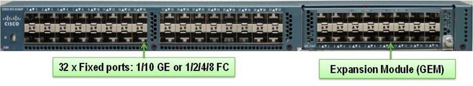
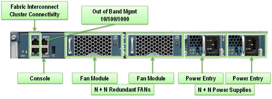
Figure 2 Cisco UCS 6248UP Fabric Interconnect – Rear View
Cisco UCS 5108 Blade Server Chassis
The Cisco UCS 5100 Series Blade Server Chassis is a crucial building block of the Cisco Unified Computing System, delivering a scalable and flexible blade server chassis. The Cisco UCS 5108 Blade Server Chassis is six rack units (6RU) high and can mount in an industry-standard 19-inch rack. A single chassis can house up to eight half-width Cisco UCS B-Series Blade Servers and can accommodate both half-width and full-width blade form factors. Four single-phase, hot-swappable power supplies are accessible from the front of the chassis. These power supplies are 92 percent efficient and can be configured to support non-redundant, N+ 1 redundant and grid-redundant configurations. The rear of the chassis contains eight hot-swappable fans, four power connectors (one per power supply), and two I/O bays for Cisco UCS 2204XP or 2208XP Fabric Extenders. A passive mid-plane provides up to 40 Gbps of I/O bandwidth per server slot and up to 80 Gbps of I/O bandwidth for two slots. The chassis is capable of supporting future 80 Gigabit Ethernet standards.
Figure 3 Cisco UCS 5108 Blade Server Chassis
Front view 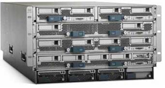
Back View 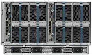
Cisco UCS B200M4 Blade Server
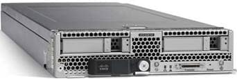
The enterprise-class Cisco UCS B200 M4 blade server extends the capabilities of Cisco’s Unified Computing System portfolio in a half-width blade form factor. The Cisco UCS B200 M4 uses the power of the latest Intel® Xeon® E5-2600 v3 Series processor family CPUs with up to 768 GB of RAM (using 32 GB DIMMs), two solid-state drives (SSDs) or hard disk drives (HDDs), and up to 80 Gbps throughput connectivity. The UCS B200 M4 Blade Server mounts in a Cisco UCS 5100 Series blade server chassis or UCS Mini blade server chassis. It has 24 total slots for registered ECC DIMMs (RDIMMs) or load-reduced DIMMs (LR DIMMs) for up to 768 GB total memory capacity (B200 M4 configured with two CPUs using 32 GB DIMMs). It supports one connector for Cisco’s VIC 1340 or 1240 adapter, which provides Ethernet and FCoE.
Figure 4 Cisco UCS B200M4 Blade Server
Cisco UCS C240M4 Rack Server
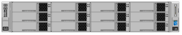
The Cisco UCS ® C240 M4 Rack Server is 2-socket, 2-rack-unit (2RU) rack server. It offers outstanding performance and expandability for a wide range of storage and I/O-intensive infrastructure workloads, from Software Defined Storages to big data and collaboration. The enterprise-class Cisco UCS C240 M4 server extends the capabilities of the Cisco Unified Computing System ™ (Cisco UCS) portfolio in a 2RU form factor with the addition of the Intel ® Xeon ® processor E5-2600 v3 product family, which delivers a superb combination of performance, flexibility, and efficiency.
Cisco UCS C240M4 servers are offered in 2 configurations:
· Cisco UCS C240 M4 LFF (Large form factor) server provides 24 DIMM slots, up to 6 PCI Express (PCIe) 3.0 slots, up to 12 front-loading LFF drives plus two (optional) internal SFF SATA boot drives for a total of 14 internal drives. It includes modular LAN on motherboard (mLOM) slot for installation of a Cisco Virtual Interface Card (VIC) or third-party network interface card (NIC) without consuming a PCI slot in addition to 2 x 1 GbE embedded (on the motherboard) LOM ports. These features combine to provide outstanding levels of internal memory and storage expandability along with exceptional performance.
· Cisco UCS C240 M4 SFF (Small form Factor) has a similar CPU and Memory configuration as LFF. However, it can take up to 24 front-loading SFF drives.
For more details please refer the following specification sheets:
Figure 5 Cisco UCS C240M4 SFF Blade Server front and rear views
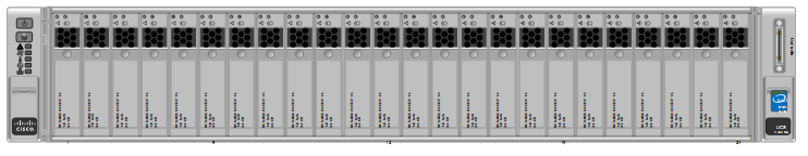
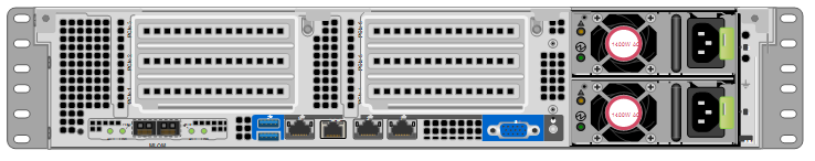
Figure 6 Cisco UCS C240M4 LFF Blade Server front and rear views
Cisco UCS Fabric Extenders
The Cisco UCS 2204XP Fabric Extender (Figure 7) has four 10 Gigabit Ethernet, FCoE-capable, SFP+ ports that connect the blade chassis to the fabric interconnect. Each Cisco UCS 2204XP has sixteen 10 Gigabit Ethernet ports connected through the mid-plane to each half-width slot in the chassis. Typically configured in pairs for redundancy, two fabric extenders provide up to 80 Gbps of I/O to the chassis.
The Cisco UCS 2208XP Fabric Extender (Figure 7) has eight 10 Gigabit Ethernet, FCoE-capable, and Enhanced Small Form-Factor Pluggable (SFP+) ports that connect the blade chassis to the fabric interconnect. Each Cisco UCS 2208XP has thirty-two 10 Gigabit Ethernet ports connected through the midplane to each half-width slot in the chassis. Typically configured in pairs for redundancy, two fabric extenders provide up to 160 Gbps of I/O to the chassis.
Figure 7 Cisco UCS 2204XP/2208XP Fabric Extender

Cisco UCS 2204XP FEX

Cisco UCS 2208XP FEX
Cisco UCS IO Adapters
Cisco VIC 1340
The Cisco UCS Virtual Interface Card (VIC) 1340 is a 2-port 40-Gbps Ethernet or dual 4 x 10-Gbps Ethernet, FCoE-capable modular LAN on motherboard (mLOM) designed exclusively for the M4 generation of Cisco UCS B-Series Blade Servers. When used in combination with an optional port expander, the Cisco UCS VIC 1340 capabilities is enabled for two ports of 40-Gbps Ethernet. The Cisco UCS VIC 1340 enables a policy-based, stateless, agile server infrastructure that can present over 256 PCIe standards-compliant interfaces to the host that can be dynamically configured as either network interface cards (NICs) or host bus adapters (HBAs).
For more information, see:
Cisco VIC 1227 MLOM
The Cisco UCS Virtual Interface Card (VIC) 1227 is a dual-port Enhanced Small Form-Factor Pluggable (SFP+) 10-Gbps Ethernet and Fibre Channel over Ethernet (FCoE)-capable PCI Express (PCIe) modular LAN-on-motherboard (mLOM) adapter designed exclusively for Cisco UCS C-Series Rack Servers (Figure 5). New to Cisco rack servers, the mLOM slot can be used to install a Cisco VIC without consuming a PCIe slot, which provides greater I/O expandability. It incorporates next-generation converged network adapter (CNA) technology from Cisco, providing investment protection for future feature releases. The card enables a policy-based, stateless, agile server infrastructure that can present up to 256 PCIe standards-compliant interfaces to the host that can be dynamically configured as either network interface cards (NICs) or host bus adapters (HBAs).
For more information see:
Cisco UCS Differentiators
Cisco’s Unified Compute System is revolutionizing the way servers are managed in data-center. Following are the unique differentiators of UCS and UCS Manager:
1. Embedded Management —In UCS, the servers are managed by the embedded firmware in the Fabric Interconnects, eliminating need for any external physical or virtual devices to manage the servers.
2. Unified Fabric —In UCS, from blade server chassis or rack servers to FI, there is a single Ethernet cable used for LAN, SAN and management traffic. This converged I/O results in reduced cables, SFPs and adapters – reducing capital and operational expenses of overall solution.
3. Auto Discovery —By simply inserting the blade server in the chassis or connecting rack server to the fabric interconnect, discovery and inventory of compute resource occurs automatically without any management intervention. The combination of unified fabric and auto-discovery enables the wire-once architecture of UCS, where compute capability of UCS can be extended easily while keeping the existing external connectivity to LAN, SAN and management networks.
4. Policy Based Resource Classification —Once a compute resource is discovered by UCS Manager, it can be automatically classified to a given resource pool based on policies defined. This capability is useful in multi-tenant cloud computing. This CVD showcases the policy based resource classification of UCS Manager.
5. Combined Rack and Blade Server Management —UCS Manager can manage B-series blade servers and C-series rack server under the same UCS domain. This feature, along with stateless computing makes compute resources truly hardware form factor agnostic.
6. Model based Management Architecture —UCS Manager Architecture and management database is model based and data driven. An open XML API is provided to operate on the management model. This enables easy and scalable integration of UCS Manager with other management systems.
7. Policies, Pools, Templates —The management approach in UCS Manager is based on defining policies, pools and templates, instead of cluttered configuration, which enables a simple, loosely coupled, data driven approach in managing compute, network and storage resources.
8. Loose Referential Integrity —In UCS Manager, a service profile, port profile or policies can refer to other policies or logical resources with loose referential integrity. A referred policy cannot exist at the time of authoring the referring policy or a referred policy can be deleted even though other policies are referring to it. This provides different subject matter experts to work independently from each-other. This provides great flexibility where different experts from different domains, such as network, storage, security, server and virtualization work together to accomplish a complex task.
9. Policy Resolution —In UCS Manager, a tree structure of organizational unit hierarchy can be created that mimics the real life tenants and/or organization relationships. Various policies, pools and templates can be defined at different levels of organization hierarchy. A policy referring to another policy by name is resolved in the organization hierarchy with closest policy match. If no policy with specific name is found in the hierarchy of the root organization, then special policy named “default” is searched. This policy resolution practice enables automation friendly management APIs and provides great flexibility to owners of different organizations.
10. Service Profiles and Stateless Computing —a service profile is a logical representation of a server, carrying its various identities and policies. This logical server can be assigned to any physical compute resource as far as it meets the resource requirements. Stateless computing enables procurement of a server within minutes, which used to take days in legacy server management systems.
11. Built-in Multi-Tenancy Support —The combination of policies, pools and templates, loose referential integrity, policy resolution in organization hierarchy and a service profiles based approach to compute resources makes UCS Manager inherently friendly to multi-tenant environment typically observed in private and public clouds.
12. Extended Memory — the enterprise-class Cisco UCS B200 M4 blade server extends the capabilities of Cisco’s Unified Computing System portfolio in a half-width blade form factor. The Cisco UCS B200 M4 harnesses the power of the latest Intel® Xeon® E5-2600 v3 Series processor family CPUs with up to 1536 GB of RAM (using 64 GB DIMMs) – allowing huge VM to physical server ratio required in many deployments, or allowing large memory operations required by certain architectures like Big-Data.
13. Virtualization Aware Network —VM-FEX technology makes the access network layer aware about host virtualization. This prevents domain pollution of compute and network domains with virtualization when virtual network is managed by port-profiles defined by the network administrators’ team. VM-FEX also off-loads hypervisor CPU by performing switching in the hardware, thus allowing hypervisor CPU to do more virtualization related tasks. VM-FEX technology is well integrated with VMware vCenter, Linux KVM and Hyper-V SR-IOV to simplify cloud management.
14. Simplified QoS —Even though Fiber Channel and Ethernet are converged in UCS fabric, built-in support for QoS and lossless Ethernet makes it seamless. Network Quality of Service (QoS) is simplified in UCS Manager by representing all system classes in one GUI panel.
Red Hat Enterprise Linux OpenStack Platform Architecture
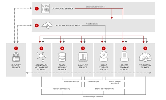
The Red Hat Enterprise Linux OpenStack Platform IaaS cloud is implemented as a collection of interacting services that control compute, storage, and networking resources. The cloud can be managed with a web-based dashboard or command-line clients, which allow administrators to control, provision, and automate OpenStack resources. OpenStack also has an extensive API, which is also available to all cloud users.
The following diagram provides a high-level overview of the OpenStack core services and their relationship with each other.
Figure 8 OpenStack Core Services and their Interdependencies
Red Hat Enterprise Linux OpenStack Platform 7 (Kilo) Services
OpenStack Networking (Neutron)
OpenStack Networking handles creation and management of a virtual networking infrastructure in the OpenStack cloud. Infrastructure elements include networks, subnets, and routers. You can also deploy advanced services such as firewalls or virtual private networks (VPN).
OpenStack Networking provides cloud administrators with flexibility to decide which individual services to run on which physical systems. All service daemons can be run on a single physical host for evaluation purposes. Alternatively, each service can have a unique physical host or replicated across multiple hosts to provide redundancy.
Because OpenStack Networking is software-defined, it can react in real-time to changing network needs, such as creation and assignment of new IP addresses.
OpenStack Networking advantages include:
· Users can create networks, control traffic, and connect servers and devices to one or more networks.
· Flexible networking models can adapt to the network volume and tenancy.
· IP addresses can be dedicated or floating, where floating IPs can be used for dynamic traffic rerouting.
Table 1 OpenStack Networking components
Service that runs on each OpenStack node to perform local networking configuration for the node virtual machines and for networking services such as Open vSwitch.
Agent that provides DHCP services to tenant networks.
Plug-in that manages network drivers and provides routing and switching services for networking services such as Open vSwitch or Ryu networks.
Python daemon that manages user requests and exposes the Networking API. The default server configuration uses a plug-in with a specific set of networking mechanisms to implement the Networking API.
Other plug-ins, such as the openvswitch and linuxbridge plug-ins, use native Linux networking mechanisms, while other plug-ins interface with external devices or SDN controllers.
Command-line client to access the API.
OpenStack Block Storage (Cinder)
OpenStack Block Storage provides persistent block storage management for virtual hard drives. Block Storage enables the user to create and delete block devices, and to manage attachment of block devices to servers.
The actual attachment and detachment of devices is handled through integration with the Compute service. You can use regions and zones to handle distributed block storage hosts.
You can use Block Storage in performance-sensitive scenarios, such as database storage or expandable file systems. You can also use it as a server with access to raw block-level storage.
Additionally, you can take volume snapshots to restore data or to create new block storage volumes. Snapshots are dependent on driver support.
OpenStack Block Storage advantages include:
· Creating, listing and deleting volumes and snapshots.
· Attaching and detaching volumes to running virtual machines.
Although the main Block Storage services, such as volume, scheduler, API, can be co-located in a production environment, it is more common to deploy multiple instances of the volume service along one or more instances of the API and scheduler services to manage them.
Table 2 Block Storage components
Responds to requests and places them in the message queue. When a request is received, the API service verifies that identity requirements are met and translates the request into a message that includes the required block storage action. The message is then sent to the message broker for processing by the other Block Storage services.
Backs up a Block Storage volume to an external storage repository. By default, OpenStack uses the Object Storage service to store the backup. You can also use Ceph, NFS, or GlusterFS back ends as storage repositories for backups.
Assigns tasks to the queue and determines the provisioning volume server. The scheduler service reads requests from the message queue and determines on which block storage host to perform the requested action. The scheduler then communicates with the openstack-cinder-volume service on the selected host to process the request.
Designates storage for virtual machines. The volume service manages the interaction with the block-storage devices. When requests arrive from the scheduler, the volume service can create, modify, or remove volumes. The volume service includes several drivers to interact with the block-storage devices, such as NFS, Red Hat Storage, or Dell EqualLogic.
Command-line client to access the Block Storage API.
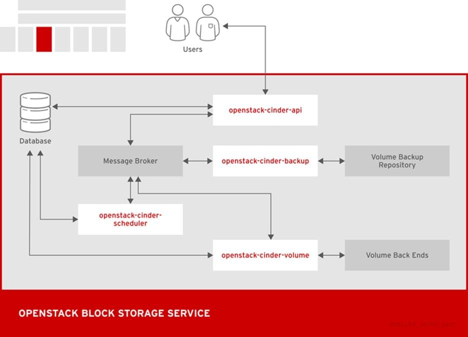
The following diagram shows the relationship between the Block Storage API, the scheduler, the volume services, and other OpenStack components.
Figure 9 OpenStack Block Storage Service
OpenStack Compute (Nova)
OpenStack Compute serves as the core of the OpenStack cloud by providing virtual machines on demand. Compute schedules virtual machines to run on a set of nodes by defining drivers that interact with underlying virtualization mechanisms, and by exposing the functionality to the other OpenStack components.
Computes supports the libvirt driver libvirtd that uses KVM as the hypervisor. The hypervisor creates virtual machines and enables live migration from node to node.
Compute interacts with the Identity service to authenticate instance and database access, with the Image service to access images and launch instances, and with the dashboard service to provide user and administrative interface.
You can restrict access to images by project and by user, and specify project and user quotes, such as the number of instances that can be created by a single user.
When you deploy a Red Hat Enterprise Linux OpenStack Platform cloud, you can break down the cloud according to different categories:
Each service cataloged in the Identity service is identified by the service region, which typically represents a geographical location, and the service endpoint. In a cloud with multiple compute nodes, regions enable discrete separation of services.
You can also use regions to share infrastructure between Compute installations while maintaining a high degree of failure tolerance.
Host Aggregates and Availability Zones
A single Compute deployment can be partitioned into logical groups. You can create multiple groups of hosts that share common resources such as storage and network, or groups that share a special property such as trusted computing hardware.
To administrators, the group is presented as a Host Aggregate with assigned compute nodes and associated metadata. The Host Aggregate metadata is commonly used to provide information for openstack-nova-scheduler actions, such as limiting specific flavors or images to a subset of hosts.
To users, the group is presented as an Availability Zone. The user cannot view the group metadata or see the list of hosts in the zone.
The benefits of aggregates, or zones, include:
· Load balancing and instance distribution.
· Physical isolation and redundancy between zones, implemented with a separate power supply or network equipment.
· Labeling for groups of servers that have common attributes.
· Separation of different classes of hardware.
Table 3 Compute components
Handles requests and provides access to the Compute services, such as booting an instance.
Provides the certificate manager.
Runs on each node to create and terminate virtual instances. The compute service interacts with the hypervisor to launch new instances, and ensures that the instance state is maintained in the Compute database.
Provides database-access support for compute nodes to reduce security risks.
Handles console authentication.
Network services that can serve as an alternative to OpenStack Networking and handle basic network traffic for private and public access.
Provides a VNC proxy for browsers to enable VNC consoles to access virtual machines.
Dispatches requests for new virtual machines to the correct node based on configured weights and filters.
Command-line client to access the Compute API.
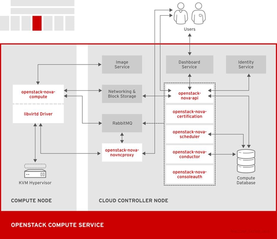
The following diagram shows the relationship between the Compute services and other OpenStack components.
Figure 10 OpenStack Compute Services
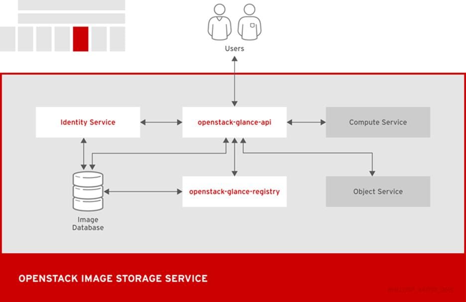
OpenStack Image (Glance)
OpenStack Image acts as a registry for virtual disk images. Users can add new images or take a snapshot of an existing server for immediate storage. You can use the snapshots for backup or as templates for new servers.
Registered images can be stored in the Object Storage service or in other locations, such as simple file systems or external Web servers.
The following image disk formats are supported:
· aki/ami/ari (Amazon kernel, ramdisk, or machine image)
· iso (archive format for optical discs, such as CDs)
· qcow2 (Qemu/KVM, supports Copy on Write)
· raw (unstructured format)
· vhd (Hyper-V, common for virtual machine monitors from vendors such as VMware, Xen, Microsoft, and VirtualBox)
Container formats can also be registered by the Image service. The container format determines the type and detail level of the virtual machine metadata to store in the image.
The following container formats are supported:
· bare (no metadata)
· ova (OVA tar archive)
· aki/ami/ari (Amazon kernel, ramdisk, or machine image)
Table 4 Image components
Interacts with storage back ends to handle requests for image retrieval and storage. The API uses openstack-glance-registry to retrieve image information. You must not access the registry service directly.
Manages all metadata for each image.
Command-line client to access the Image API.
The following diagram shows the main interfaces that the Image service uses to register and retrieve images from the Image database.
Figure 11 OpenStack Image Storage Service
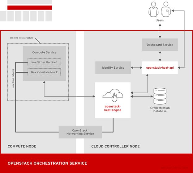
OpenStack Orchestration (Heat)
OpenStack Orchestration provides templates to create and manage cloud resources such as storage, networking, instances, or applications. Templates are used to create stacks, which are collections of resources.
For example, you can create templates for instances, floating IPs, volumes, security groups, or users. Orchestration offers access to all OpenStack core services with a single modular template, as well as capabilities such as auto-scaling and basic high availability.
OpenStack Orchestration advantages include:
· A single template provides access to all underlying service APIs.
· Templates are modular and resource-oriented.
· Templates can be recursively defined and reusable, such as nested stacks. The cloud infrastructure can then be defined and reused in a modular way.
· Resource implementation is pluggable, which allows for custom resources.
· Resources can be auto-scaled, and therefore added or removed from the cluster based on usage.
· Basic high availability functionality is available.
Table 5 Orchestration Components
OpenStack-native REST API that processes API requests by sending the requests to the openstack-heat-engine service over RPC.
Optional AWS-Query API compatible with AWS CloudFormation that processes API requests by sending the requests to the openstack-heat-engine service over RPC.
Orchestrates template launch and generates events for the API consumer.
Package of helper scripts such as cfn-hup, which handle updates to metadata and execute custom hooks.
Command-line tool that communicates with the Orchestration API to execute AWS CloudFormation APIs.
The following diagram shows the main interfaces that the Orchestration service uses to create a new stack of two new instances and a local network.
Figure 12 OpenStack Orchestration Service
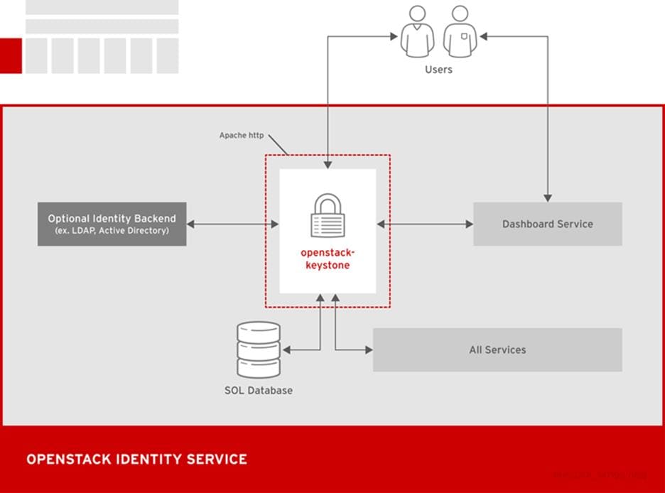
OpenStack Identity (Keystone)
OpenStack Identity provides user authentication and authorization to all OpenStack components. Identity supports multiple authentication mechanisms, including user name and password credentials, token-based systems, and AWS-style log-ins.
By default, the Identity service uses a MariaDB back end for token, catalog, policy, and identity information. This back end is recommended for development environments or to authenticate smaller user sets. You can also use multiple identity back ends concurrently, such as LDAP and SQL. You can also use memcache or Redis for token persistence.
Identity supports Federation with SAML. Federated Identity establishes trust between Identity Providers (IdP) and the services that Identity provides to the end user.
 Federated Identity and concurrent multiple back ends require Identity API v3 and Apache HTTPD deployment instead of Eventlet deployment.
OpenStack Identity advantages include:
· User account management, including associated information such as a name and password. In addition to custom users, a user must be defined for each cataloged service. For example, the glance user must be defined for the Image service.
· Tenant, or project, management. Tenants can be the user group, project, or organization.
· Role management. Roles determine the user permissions. For example, a role might differentiate between permissions for a sales rep and permissions for a manager.
· Domain management. Domains determine the administrative boundaries of Identity service entities, and support multi-tenancy, where a domain represents a grouping of users, groups, and tenants. A domain can have more than one tenant, and if you use multiple concurrent Identity providers, each provider has one domain.
Table 6 Identity Components
Provides Identity services, together with the administrative and public APIs. Both Identity API v2 and API v3 are supported.
Command-line client to access the Identity API.
The following diagram shows the basic authentication flow that Identity uses to authenticate users with other OpenStack components.
Figure 13 OpenStack Identity Service
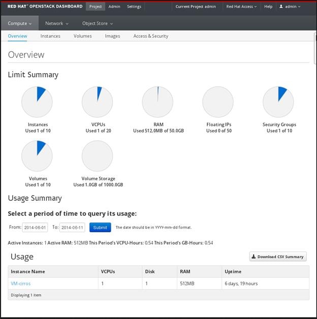
OpenStack Dashboard (Horizon)
OpenStack Dashboard provides a graphical user interface for users and administrators to perform operations such as creating and launching instances, managing networking, and setting access control.
The Dashboard service provides the Project, Admin, and Settings default dashboards. The modular design enables the dashboard to interface with other products such as billing, monitoring, and additional management tools.
The following image shows an example of the Compute panel in the Admin dashboard.
Figure 14 RedHat OpenStack Dashboard
The role of the user that logs in to the dashboard determines which dashboards and panels are available.
Table 7 Dashboard Components
Django Web application that provides access to the dashboard from any Web browser.
Apache HTTP server (httpd service)
Hosts the application.
The following diagram shows an overview of the dashboard architecture.
Figure 15 OpenStack Dashboard Services
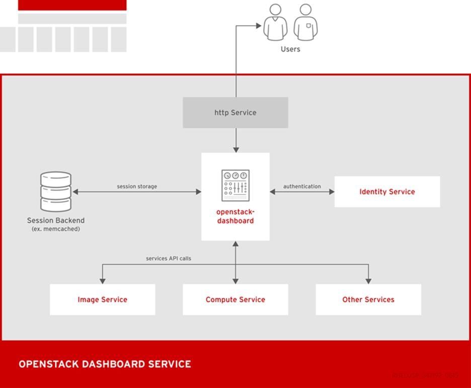
The example shows the following interaction:
· The OpenStack Identity service authenticates and authorizes users
· The session back end provides database services
· The httpd service hosts the Web application and all other OpenStack services for API calls
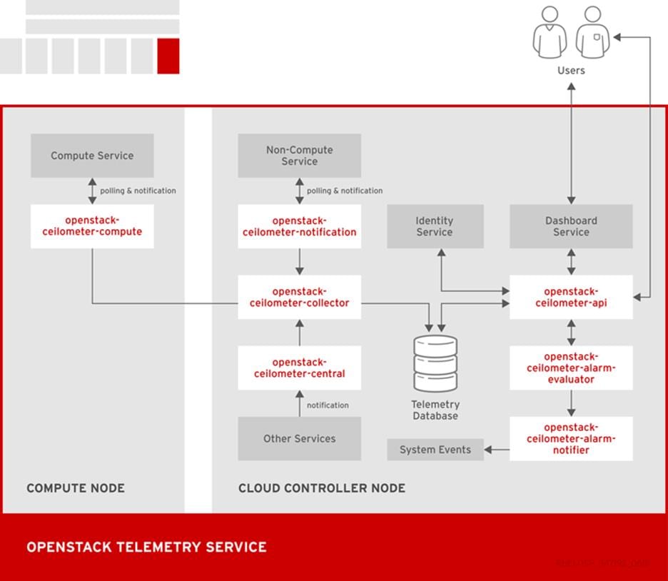
OpenStack Telemetry (Ceilometer)
OpenStack Telemetry provides user-level usage data for OpenStack-based clouds. The data can be used for customer billing, system monitoring, or alerts. Telemetry can collect data from notifications sent by existing OpenStack components such as Compute usage events, or by polling OpenStack infrastructure resources such as libvirt.
Telemetry includes a storage daemon that communicates with authenticated agents through a trusted messaging system to collect and aggregate data. Additionally, the service uses a plug-in system that you can use to add new monitors. You can deploy the API Server, central agent, data store service, and collector agent on different hosts.
The service uses a MongoDB database to store collected data. Only the collector agents and the API server have access to the database.
Table 8 Telemetry Components
Triggers state transitions on alarms.
Executes actions when alarms are triggered.
Runs on one or more central management servers to provide access to data in the database.
Runs on a central management server to poll for utilization statistics about resources independent from instances or Compute nodes. The agent cannot be horizontally scaled, so you can run only a single instance of this service at a time.
Runs on one or more central management servers to monitor the message queues. Each collector processes and translates notification messages to Telemetry messages, and sends the messages back to the message bus with the relevant topic.
Telemetry messages are written to the data store without modification. You can choose where to run these agents, because all intra-agent communication is based on AMQP or REST calls to the ceilometer-api service, similar to the ceilometer-alarm-evaluator service.
Runs on each Compute node to poll for resource utilization statistics. Each nova-compute node must have a ceilometer-compute agent deployed and running.
Pushes metrics to the collector service from various OpenStack services.
Command-line client to access the Telemetry API.
The following diagram shows the interfaces used by the Telemetry service.
Figure 16 OpenStack Telemetry Service
Third-party Components
Some Red Hat Enterprise Linux OpenStack Platform components use third-party databases, services, and tools.
Databases
· MariaDB is the default database that is shipped with Red Hat Enterprise Linux. MariaDB enables Red Hat to fully support open source community-developed software. Each OpenStack component except Telemetry requires a running MariaDB service. Therefore, you need to deploy MariaDB before you deploy a full OpenStack cloud service or before you install any standalone OpenStack component.
· The Telemetry service uses a MongoDB database to store collected usage data from collector agents. Only the collector agents and the API server have access to the database.
Messaging
RabbitMQ is a robust open-source messaging system based on the AMQP standard. RabbitMQ is a high-performance message broker used in many enterprise systems with widespread commercial support. In Red Hat Enterprise Linux OpenStack Platform, RabbitMQ is the default and recommended message broker.
RabbitMQ managers OpenStack transactions including queuing, distribution, security, management, clustering, and federation. It also serves a key role in high availability and clustering scenarios.
External Caching
External applications for caching, such as memcached or Redis, offer persistence and shared storage and speed up dynamic web applications by reducing the database load. External caching is used by various OpenStack components, for example:
· The Object Storage service uses memcached to cache authenticated clients, instead of requiring each client to re-authorize each interaction.
· By default, the dashboard uses memcached for session storage.
· The Identity service uses Redis or memcached for token persistence.
Red Hat Ceph Storage
Red Hat Ceph is a distributed data object store designed to provide excellent performance, reliability and scalability. Distributed object stores are the future of storage, because they accommodate unstructured data, and because clients can use modern object interfaces and legacy interfaces simultaneously. For example:
· Native language binding interfaces (C/C++, Java, Python)
· RESTful interfaces (S3/Swift)
· Block device interfaces
The power of Red Hat Ceph can transform your organization’s IT infrastructure and your ability to manage vast amounts of data, especially for cloud computing platforms like Red Hat Enterprise Linux OpenStack Platform. Red Hat Ceph delivers industry-leading scalability –thousands of clients accessing petabytes to exabytes of data and beyond.
At the heart of every Ceph deployment is the Ceph Storage Cluster. It consists of two types of daemons:
· Ceph OSD Daemon: Ceph OSDs store data on behalf of Ceph clients. Additionally, Ceph OSDs utilize the CPU and memory of Ceph nodes to perform data replication, rebalancing, recovery, monitoring and reporting functions.
· Ceph Monitor: A Ceph monitor maintains a master copy of the Ceph storage cluster map with the current state of the storage cluster.
Ceph client interfaces read data from and write data to the Ceph storage cluster. Clients need the following data to communicate with the Ceph storage cluster:
· The Ceph configuration file, or the cluster name (usually ceph) and monitor address
· The user name and the path to the secret key.
Ceph clients maintain object IDs and the pool name(s) where they store the objects, but they do not need to maintain an object-to-OSD index or communicate with a centralized object index to look up data object locations. To store and retrieve data, Ceph clients access a Ceph monitor and retrieve the latest copy of the storage cluster map. Then, Ceph clients can provide an object name and pool name, and Ceph will use the cluster map and the CRUSH (Controlled Replication under Scalable Hashing) algorithm to compute the object placement group and the primary Ceph OSD for storing or retrieving data. The Ceph client connects to the primary OSD where it may perform read and write operations. There is no intermediary server, broker or bus between the client and the OSD.
When an OSD stores data, it receives data from a Ceph client— whether the client is a Ceph Block Device, a Ceph Object Gateway or another interface— and it stores the data as an object. Each object corresponds to a file in a filesystem, which is stored on a storage device such as a hard disk. Ceph OSDs handle the read/write operations on the storage device.
Ceph OSDs store all data as objects in a flat namespace (e.g., no hierarchy of directories). An object has a cluster-wide unique identifier, binary data, and metadata consisting of a set of name/value pairs. The semantics are completely up to Ceph clients. For example, the Ceph block device maps a block device image to a series of objects stored across the cluster.
Storage Cluster Architecture
A Ceph Storage Cluster accommodates large numbers of Ceph nodes for effectively massive scalability, high availability and performance. Each node leverages commodity hardware and intelligent Ceph daemons that communicate with each other to:
· Store and retrieve data
· Monitor and report on cluster health (heartbeating)
· Redistribute data dynamically (backfilling)
· Ensure data integrity (scrubbing)
· Recover from failures.
To the Ceph client interface that reads and writes data, a Ceph storage cluster looks like a simple pool where it stores data. However, the storage cluster performs many complex operations in a manner that is completely transparent to the client interface. Ceph clients and Ceph OSDs both use the CRUSH (Controlled Replication under Scalable Hashing) algorithm. Ceph Client Architecture.
Ceph Client Architecture
Ceph clients differ in their materially in how they present data storage interfaces. A Ceph block device presents block storage that mounts just like a physical storage drive. A Ceph gateway presents an object storage service with S3-compliant and Swift-compliant RESTful interfaces with its own user management. However, all Ceph clients use the Reliable Autonomic Distributed Object Store (RADOS) protocol to interact with the Ceph storage cluster; and, they all have the same basic needs:
· The Ceph configuration file, or the cluster name (usually ceph) and monitor address
· The user name and the path to the secret key.
Ceph clients tend to follow some similar patterns, such as object-watch-notify and striping.
RedHat Enterprise Linux OpenStack Platform 7 director
Red Hat Enterprise Linux OpenStack Platform, is an integrated foundation, to create, deploy, and scale a secure and reliable public or private OpenStack cloud. Red Hat Enterprise Linux OpenStack Platform starts with the proven foundation of Red Hat Enterprise Linux and integrates Red Hat’s OpenStack Platform technology to provide a production-ready cloud platform backed by an ecosystem of more than 350 certified partners.
Red Hat Enterprise Linux OpenStack Platform 7 is based on the community Kilo OpenStack release. This release is Red Hat’s fifth iteration of Red Hat Enterprise Linux OpenStack Platform which has been successfully deployed by Red Hat customers worldwide across diverse vertical industries including financial, telecommunications, and education.
Red Hat Enterprise Linux OpenStack Platform 7 introduces Red Hat Enterprise Linux OpenStack Platform director, a cloud installation and lifecycle management tool chain. Director is the first Red Hat Enterprise Linux OpenStack Platform installer to deploy OpenStack on and with OpenStack. This section introduces Red Hat Enterprise Linux OpenStack Platform director’s architecture and describes the following features:
· Simplified deployment through ready-state provisioning of bare metal resources.
· Flexible network definitions
· High availability via tight integration with the Red Hat Enterprise Linux Server High Availability Add-on
· Integrated setup and installation of Red Hat Ceph Storage
· Content management via the Red Hat Content Delivery Network or Red Hat Satellite Server
Ready State Provisioning and Server Roles
Red Hat Enterprise Linux OpenStack Platform director is a converged installer. It combines mature upstream OpenStack deployment projects (TripleO and Ironic) with components from Red Hat’s past Red Hat Enterprise Linux OpenStack Platform installers.
TripleO stands for OpenStack on OpenStack. TripleO is an upstream OpenStack project that uses an existing OpenStack environment to install a production OpenStack environment. The deployment environment is called the undercloud. The production environment is called overcloud.
The undercloud is the TripleO control plane. It uses native OpenStack APIs and services to deploy, configure, and manage the production OpenStack deployment. The undercloud defines the overcloud with Heat templates and then deploys it via the Ironic baremetal provisioning service. Red Hat Enterprise Linux OpenStack Platform director includes Heat predefined templates for the basic server roles that comprise the overcloud. Customizable templates allow director to deploy, redeploy, and scale complex overclouds in a repeatable fashion.
Ironic is a community bare-metal provisioning project. Director uses Ironic to deploy the overcloud servers. Ironic gathers information about baremetal servers via a discovery mechanism known as introspection. Ironic pairs servers with a bootable disk image and then installs them via PXE and remote power management.
Red Hat Enterprise Linux OpenStack Platform director deploys all servers with the same generic image by injecting Puppet modules into the generic disk image to tailor it for specific server roles. It then applies host-specific customizations via Puppet including network and storage configurations.
While the undercloud is primarily used to deploy OpenStack, overcloud is a functional cloud available to run virtual machines and workloads. Servers in the following roles comprise the overcloud:
Control
This role provides the endpoint for REST-based API queries to the majority of the OpenStack services. These include Compute, Image, Identity, Block, Network, and Data processing. The controller can run as a standalone server or as a HA cluster.
Compute
This role provides the processing, memory, storage, and networking resources to run virtual machine instances. They run the KVM hypervisor by default. New instances are spawned across compute nodes in a round-robin fashion.
Ceph Storage
Ceph is a distributed object store and file system. This role deploys Object Storage Daemon (OSD) nodes for Ceph clusters. It also installs the Ceph Monitor service on the controller.
Red Hat Enterprise Linux OpenStack Platform director also includes advanced hardware configuration tools. These tools validate server hardware prior to installation. Profile matching lets administrators specify hardware requirements for each server role. Red Hat Enterprise Linux OpenStack Platform director only matches servers that meet minimum hardware requirements for each role. Profile to matching is performed after introspection but prior to deployment.
Red Hat Enterprise Linux OpenStack Platform director also supports pre-installation benchmark collection. Servers boot to a customized RAMdisk and run a series of benchmarks. The benchmarks report performance outliers to identify underperforming nodes prior to installation.
Network Isolation
OpenStack requires multiple network functions. While it is possible to collapse all network functions onto a single network interface, isolating communication streams in their own physical or virtual networks provides better performance and scalability.
Red Hat Enterprise Linux OpenStack Platform director supports isolating network traffic by type. One or more network traffic types can be assigned to a physical, virtual, or bonded interface. It is to be noted however that LACP bonding mode is not possible when Cisco UCS Fabric Interconnects are in use. Multiple traffic types can be combined across the same physical interfaces or switches. Each OpenStack service is bound to an IP on a particular network. A virtual IP is created on that network and shared among all of the HA controllers.
Red Hat Enterprise Linux OpenStack Platform director supports network isolation for the following traffic types:
Provisioning
The control plane installs the overcloud via this network. All cluster nodes must have a physical interface attached to the provisioning network. This network carries DHCP/PXE and TFTP traffic so it must be provided on a dedicated interface or a native VLAN to the boot interface. The provisioning interface can act as a default gateway for the overcloud if there is no other gateway on the network. Disable PXE on the remaining interfaces to ensure the servers boot from this network.
External
The External network is used for hosting the Horizon dashboard and the Public APIs, as well as hosting the floating IPs that are assigned to VMs. The Neutron L3 routers which perform NAT are attached to this interface. The range of IPs that are assigned to floating IPs should not include the IPs used for hosts and VIPs on this network.
Internal API
This network is used for connections to the API servers, as well as RPC messages using
RabbitMQ and connections to the database. The Glance Registry API uses this network, as does the Cinder API. This network is typically only reachable from inside the OpenStack Overcloud environment, so API calls from outside the cloud will use the Public APIs.
Tenant
Virtual machines communicate over the tenant network. It supports three modes of operation: VXLAN, GRE, and VLAN. VXLAN and GRE tenant traffic is delivered via software tunnels on a single VLAN. Individual VLANs correspond to tenant networks in the case where VLAN tenant networks are used.
Storage
This network carries storage communication including Ceph, Cinder, and Swift traffic. The virtual machine instances communicate with the storage servers via this network. Data-intensive OpenStack deployments should isolate storage traffic on a dedicated high bandwidth interface, i.e. 10 GB interface. The Glance API, Swift proxy, and Ceph Public interface services are all delivered via this network.
Storage Management
Storage management communication can generate large amounts of network traffic. This network is shared between the front and back end storage nodes. Storage controllers use this network to access data storage nodes. This network is also used for storage clustering and replication traffic.
Network traffic types are assigned to network interfaces through Heat template customizations prior to deploying the overcloud. Red Hat Enterprise Linux OpenStack Platform director supports several network interface types including physical interfaces, bonded interfaces (not with Cisco UCS Fabric Interconnects), and either tagged or native 802.1Q VLANs.
Network Types by Server Role
The previous section discussed server roles. Each server role requires access to specific types of network traffic. The network isolation feature allows Red Hat Enterprise Linux OpenStack Platform director to segment network traffic by particular network types. When using network isolation, each server role must have access to its required network traffic types.
By default, Red Hat Enterprise Linux OpenStack Platform director collapses all network traffic to the provisioning interface. This configuration is suitable for evaluation, proof of concept, and development environments. It is not recommended for production environments where scaling and performance are primary concerns. Table below summarizes the required network types by server role.
Tenant Network Types
Red Hat Enterprise Linux OpenStack Platform 7 supports tenant network communication through the OpenStack Networking (Neutron) service. OpenStack Networking supports overlapping IP address ranges across tenants via the Linux kernel’s network namespace capability. It also supports three default networking types:
VLAN segmentation mode
Each tenant is assigned a network subnet mapped to a 802.1q VLAN on the physical network. This tenant networking type requires VLAN-assignment to the appropriate switch ports on the physical network.
The GRE (Generic Routing Encapsulation) type driver provides an alternative form of network segregation. Virtual networks are created within Neutron, and then associated with VMs in Nova. When VMs are launched, the mechanism driver attaches the virtual network interface of the VM to a virtual network. The mechanism driver on the Compute host forms GRE tunnels between the virtual network interface of the VM and the virtual network interface of all other VMs on the same virtual network. This mesh is used both for point-to-point traffic between one VM and another, and broadcast traffic, which is sent simultaneously to all VMs on the virtual network.
VXLAN
The VXLAN (Virtual Extensible LAN) type driver provides another method of network segregation. Virtual networks are created within Neutron, and then associated with VMs in Nova. When VMs are launched, the mechanism driver attaches the virtual network interface of the VM to a virtual network. VXLAN Segment IDs provides network segmentation and isolation, and Neutron uses Linux Network Namespaces to allow overlapping IP address ranges between the virtual networks
High Availability
Red Hat Enterprise Linux OpenStack Platform director’s approach to high availability OpenStack leverages Red Hat’s internal expertise with distributed cluster systems. Most of the technologies discussed in this section are available through the Red Hat Enterprise Linux Server High Availability Add On. These technologies are bundled with Red Hat Enterprise Linux OpenStack Platform 7 to provide cluster services for production deployments.
Cluster Manager and Proxy Server
Two components drive HA for all core and non-core OpenStack services: the cluster manager and the proxy server.
The cluster manager is responsible for the startup and recovery of an inter-related services across a set of physical machines. It tracks the cluster’s internal state across multiple machines. State changes trigger appropriate responses from the cluster manager to ensure service availability and data integrity.
Cluster Manager Benefits
· Deterministic recovery of a complex, multi-machine application stack
· State awareness of other cluster machines to co-ordinate service startup and failover.
· Shared quorum calculation to determine majority set of surviving cluster nodes after a failure.
· Data integrity through fencing. Machines running a non-responsive process are isolated to ensure they are not still responding to remote requests. Machines are typically fenced via a remotely accessible power switch or IPMI controller.
· Automated recovery of failed instances to prevent additional load-induced failures.
· In Red Hat Enterprise Linux OpenStack Platform’s HA model, clients do not directly connect to service endpoints. Connection requests are routed to service endpoints by a proxy server.
Proxy Server Benefits
· Connections are load balanced across service endpoints
· Service requests can be monitored in a central location
· Cluster nodes can be added or removed without interrupting service
Red Hat Enterprise Linux OpenStack Platform director uses HAproxy and Pacemaker to manage HA services and load balance connection requests. With the exception of RabbitMQ and Galera, HAproxy distributes connection requests to active nodes in a round-robin fashion. Galera and RabbitMQ use persistent options to ensure requests go only to active and/or synchronized nodes. Pacemaker checks service health at 1 second intervals. Timeout settings vary by service.
Benefits of combining Pacemaker and HAproxy:
· Detects and recovers machine and application failures
· Starts and stops OpenStack services in the correct order
· Responds to cluster failures with appropriate actions including resource failover and machine restart and fencing
· Provides a thoroughly tested code base that has been used in production clusters across a variety of use cases.
The following services deployed by Red Hat Enterprise Linux OpenStack Platform director do not use the proxy server:
Individual cluster services are discussed in the following section.
Cluster Services and Quorum
Each clustered service operates in one of the following modes:
Active/active
Requests are load balanced between multiple cluster nodes running the same services. Traffic intended for failed nodes is sent to the remaining nodes.
Active/passive
A redundant copy of a running service is brought online when the primary node fails.
Hot Standby
Connections are only routed to one of several active service endpoints. New connections are routed to a standby endpoint if the primary service endpoint fails.
Mixed
Mixed has one of two meanings: services within a group run in different modes, or the service runs active/active but is used as active/passive. Mixed services are explained individually.
Single
Each node runs an independent cluster manager that only monitors its local service.
A cluster quorum is the majority node set when a failure splits the cluster into two or more partitions. In this situation the majority fences the minority to ensure both sides are not running the same services — a so-called split brain situation. Fencing is the process of isolating a failed machine — typically via remote power control or networked switches — by powering it off. This is necessary to ensure data integrity.
Cluster Modes for Core Services
This section of the paper describes Red Hat Enterprise Linux OpenStack Platform director’s default cluster mode for each OpenStack service.
The following table lists service mode by service.
Table 9 OpenStack Services with its Cluster Mode
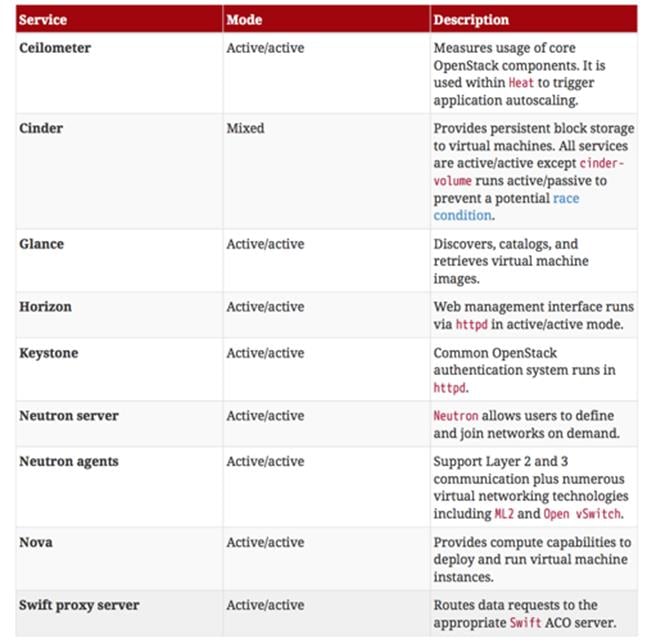
Cluster Modes for Supporting Services
The majority of the core OpenStack services run in active/active mode. The same is true for the supporting services, although several of them field connection requests directly from clients rather than HAproxy.
The following table lists the cluster mode for the non-core OpenStack services.
Figure 17 Non-core OpenStack Services with its Cluster Mode

Compute Node Clustering
Red Hat Enterprise Linux OpenStack Platform installs compute nodes as single-node clusters in order to monitor their health and that of the services running on them.
In the event that a compute node fails, Pacemaker restarts compute node services in the following order:
If a service fails to start, the node where the service is running will be fenced in order to guarantee data integrity.
Ceph Storage Integration
Red Hat Ceph Storage 1.3 is a distributed data object store designed for performance, reliability, and scalability. Red Hat Enterprise Linux OpenStack Platform 7 director can deploy an integrated Ceph cluster in the overcloud. The integrated Ceph cluster acts as a storage virtualization layer for Glance images, Cinder volumes, and Nova ephemeral storage. Figure 18 below depicts Red Hat Enterprise Linux OpenStack Platform 7 director Ceph cluster integration from a high level. The Ceph cluster consists of two types of daemons: Ceph OSD and Ceph Monitor. The Ceph OSD Daemon stores data in pools striped across one or more disks. Ceph OSDs also replicate, rebalance, and recover data, and report data usage.
The Ceph Monitor maintains a master copy of the Ceph storage map and the current state of the storage cluster. Ceph clients consult the Ceph monitor to receive the latest copy of the storage map then communicate directly with the primary data-owning OSD.
Figure 18 Ceph Integration

Red Hat Enterprise Linux OpenStack Platform director can install a Ceph cluster with one or more OSD servers. By default the OSD server will use free space on its primary disk for the OSD storage device. Additional OSDs can be configured through Puppet customizations prior to deploying overcloud. Ceph performance scales with the number of OSD disks. The Ceph monitor is installed on the controller nodes whenever a Ceph storage role is deployed in overcloud.
OpenStack Networking ML2 Core
Conventional Neutron suffered from the one driver syndrome i.e. only a single plugin could be loaded in any deployment. There was no clean way to get multiple drivers working seamlessly together. There was also a huge amount of duplicate code across the drivers e.g. everyone had to manage segments for their drivers. To address these issues, the Modular Layer 2 plugin (ML2) was created with an architecture allowing multiple type drivers and mechanism drivers to manage details of specific network segment types and networking mechanisms for implementing segments. Type drivers manage a type of network, namely segmentation and allocation for that network type. A VLAN type driver will manage allocation of VLAN segments for a VLAN type network. Mechanism drivers are drivers that manage specific mechanisms like vendor devices, open source devices. Every device needs a mechanism driver to integrate with Neutron e.g. OVS, Cisco Nexus, APIC etc. Cisco has separate mechanism drivers for Cisco Nexus Switches, Cisco Application Policy Infrastructure Controller, Cisco Nexus 1000V etc.
Cisco UCS Plugins
Cisco Nexus 1000V Plugin
Cisco Nexus 1000V OpenStack solution is an enterprise-grade virtual networking solution, which offers Security, Policy control and Visibility all with Layer2/Layer 3 switching at the hypervisor layer. Cisco Nexus 1000V provides stateful firewall functionality within your infrastructure to isolate tenants and enables isolation of virtual machines with policy-based VM attributes. Cisco Nexus 1000V’s robust policy framework enables centralized enterprise-compliant policy management, pre-provisioning of policies on a network-wide basis and simplifies policy additions and modifications across the virtual infrastructure. When it comes to application visibility, Cisco Nexus 1000V provides insight into live and historical VM migrations and advanced automated troubleshooting capabilities to identify problems in seconds. It also enables you to use your existing monitoring tools to provide rich analytics and auditing capabilities across your physical and virtual infrastructure.
· Layer2/Layer3 Switching – Cisco Nexus 1000V offers the capability to route traffic within the tenant without having to go to an external router. This capability reduces sub-optimal traffic patterns within the network and increases the network performance.
· Security – Cisco Nexus 1000V is compatible with Cisco Virtual Security Gateway (VSG) which provides layer 2 zone based firewall capability. Using VSG, Nexus 1000V can secure traffic by providing stateful firewall functionality. VSG enables the users to define security attributes based on network attributes.
· Policy Frame Work – Cisco Nexus 1000V provides an extremely powerful policy frame work to define polices per tenant and make these policies available to the end user via Horizon Dashboard or via Neutron API. All these polices can be centrally managed which makes it easier to roll out new business polices or modify existing business polices instantaneously
· Application Visibility – Nexus 1000V brings in a slew of industry proven monitoring features that exist in the physical Nexus infrastructure to virtual networking. To name a few of them, Nexus 1000V provides remote-monitoring capabilities by using SPAN/ERSPAN, provides visibility into VM motion by using vTacker and provides consolidated interface status, traffic statistics using Virtual Supervisor Module (VSM)
All the monitoring, management and functionality features offered on the Nexus 1000V are consistent with the physical Nexus infrastructure. This enables customer to reuse the existing tool chains to manage the new virtual networking infrastructure as well. Along with this, customer can also have the peace of mind that the feature functionality they enjoyed in the physical network will now be the same in the virtual network.
Cisco Nexus 1000V Components
Nexus 1000v brings the same robust architecture associated with traditional Cisco physical modular switches and with other virtualization environments (for example, VMware vSphere and Microsoft Hyper-V) to OpenStack deployments.
The Nexus1000v has the following main components:
· The Cisco Nexus® 1000V Virtual Ethernet Module (VEM) is a software component that is deployed on each Kernel-based Virtual Machine (KVM) host. Each virtual machine on the host is connected to the VEM through virtual Ethernet (vEth) ports.
· The Cisco Nexus 1000V Virtual Supervisor Module (VSM) is the management component that controls multiple VEMs and helps in the definition of virtual machine-focused network policies. It is deployed on Controllers in Active/Standby mode.
· The OpenStack Neutron ML2 driver for Nexus 1000v is used for communication between the VSM and OpenStack Neutron service and is deployed as part of the OpenStack Neutron service.
· The OpenStack Horizon integration for policy profile.
Each of these components are tightly integrated with the OpenStack environment:
· The VEM is a hypervisor-resident component and is tightly integrated with the KVM architecture.
· The VSM is integrated with OpenStack using the OpenStack Neutron ML2 driver for Nexus 1000v.
· The OpenStack Neutron API has been extended to include one additional user-defined resource:
— Policy profiles group port policy information used for features such as Security (ACL’s), monitoring, VLAN trunk, PVLAN, Netflow and IGMP snooping.
Figure 19 Cisco Nexus 1000V with OpenStack
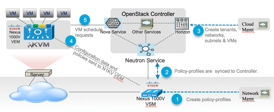
Cisco Nexus Plugin
The Cisco Nexus driver for OpenStack Neutron allows customers to easily build their infrastructure-as-a-service (IaaS) networks using the industry’s leading networking platform, delivering performance, scalability, and stability with the familiar manageability and control you expect from Cisco® technology.
The Cisco Nexus driver for OpenStack Neutron is capable of configuring Layer 2 tenant networks on the physical Nexus switches using either VLAN or VXLAN networks.
VLAN Programming
The Cisco Nexus Mechanism Driver (MD) for the Modular Layer 2 (ML2) plugin can configure VLANs on Cisco Nexus switches through OpenStack Neutron. The MD efficiently and intelligently uses VLAN ID assignment on switch ports by provisioning and deprovisioning VLANs across switches as virtual machines connected to tenant networks are created and destroyed. Moreover, connectivity from the compute hosts to the physical network is trunked to allow traffic only from the VLANs configured on the host by the virtual switch.
VXLAN Configuration
VXLAN is designed to provide the same Ethernet Layer 2 connectivity as VLAN, but with greater extensibility and flexibility. Hardware based VXLAN functions on the Nexus platform map VLANs tagged by the virtual switch on the host into VXLAN tunnels on physical switches. VLAN allocations are localized per switch, enabling tenant networks to reuse VLANs across switches.
Multi-homed Host Deployments
Highly available OpenStack network configurations are now possible using virtual Port Channels (vPCs). In addition to the standard Ethernet interfaces, the driver can also provision and deprovision tenant VLANs dynamically and efficiently on Cisco Nexus PortChannel interfaces.
Cisco UCS Manager Plugin
Cisco UCS Manager Plugin has three main functions.
· Configure UCS Compute blades and managers with necessary VLANS.
· Configure SR-IOV capable virtual functions and
· Configure Cisco VM-FEX on SR-IOV capable NIC’s.
The UCS Manager Plugin talks to the UCS Manager application running on Fabric Interconnect. The UCS Manager is part of an ecosystem for UCS Servers that consists of Fabric Interconnects and IO modules.
The SR-IOV/VM-FEX feature allows Cisco and Intel (only SR-IOV support) physical functions (NICs) to be split into several virtual functions. These virtual functions can be configured in either the Direct or Macvtap modes. In both these modes, the virtual functions can be assigned to Nova VM’s, causing traffic from the VM’s to bypass the hypervisor and sent directly to the Fabric Interconnect. This feature increases traffic throughput to the VM and reduces CPU load on the UCS Servers. In «Direct» SR-IOV/VM-FEX mode, these benefits are the greatest with the limitation that live migration of the VM to a different Server cannot be supported.
The ML2 UCS Manager driver does not support configuration of UCS Servers, whose service profiles are attached to Service Templates. This is to prevent that same VLAN configuration to be pushed to all the service profiles based on that template. The plugin can be used after the Service Profile has been unbound from the template.
Cisco Nexus 9000 Switches
The Cisco Nexus 9000 Series delivers proven high performance and density, low latency, and exceptional power efficiency in a broad range of compact form factors. Operating in Cisco NX-OS Software mode or in Application Centric Infrastructure (ACI) mode, these switches are ideal for traditional or fully automated data center deployments.
The Cisco Nexus 9000 Series Switches offer both modular and fixed 10/40/100 Gigabit Ethernet switch configurations with scalability up to 30 Tbps of non-blocking performance with less than five-microsecond latency, 1152 10 Gbps or 288 40 Gbps non-blocking Layer 2 and Layer 3 Ethernet ports and wire speed VXLAN gateway, bridging, and routing
Figure 20 Cisco Nexus 9372 switch
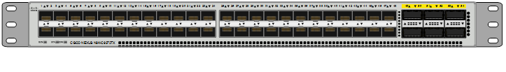
Solution Design
The following sections give an overview of the hardware and software components used on the test bed, and few design factors to consider while making the system to work as a single highly available system.
Architectural Overview
The below figure shows the physical topology of the test bed and it has the following components:
Cisco UCS B200 M4 Blade Server
The director or undercloud node, controllers and compute nodes are on B200M4 blades. The compute nodes are evenly distributed across the pair of 5108 chassis. Each chassis has to host a minimum of one controller node. The director or undercloud node can be seated in any one of the chassis. The traffic flow through director node is minimal.
Cisco UCS C240 M4 Rack Servers
Cisco C-series rack servers provide the storage requirements to the OpenStack environment. However these are managed by UCS and hence are connected to Fabric Interconnects. We can leverage the full management capabilities of UCS Manager by hooking the storage servers to fabrics.
Cisco UCS Fabric Interconnects and Cisco Nexus Switches
There is a pair of Fabric interconnects, which is standard per UCS design. Both the fabrics operate in active-active mode in addition to the inbuilt failover capabilities. Same applies to pair of Nexus switches. The Nexus switches operate in Virtual Port Channel (vPC).
IO Modules
IO Modules connect the chassis to fabrics. These carry the FCoE traffic to the fabric interconnects.
Recommended Configuration
A minimum of 3 controllers, 3 storage nodes and 1 compute nodes are recommended to achieve High Availability in stack. More Compute or Ceph nodes can be added as needed. A full scale testing will be done with 3 fully populated chassis with Cisco UCS B200 M4 blades and with 10-12 storage nodes. The details of these configurations and test results will be included in the deployment guide.
Figure 21 Physical Topology
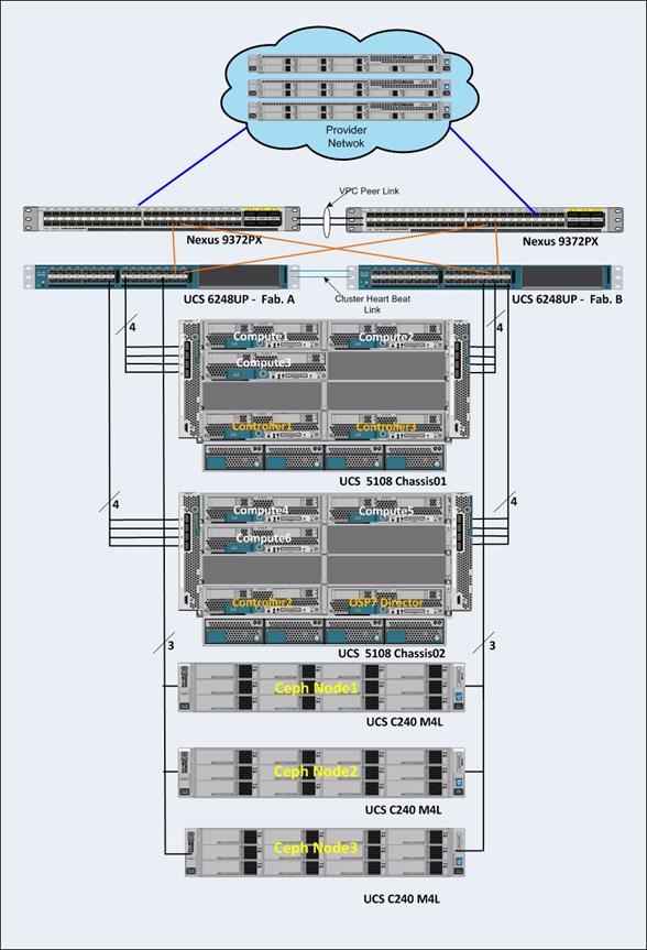
System Hardware and Software Specifications
The below table lists the Hardware and Software releases used for solution verification.
Источник


