- Скачать бесплатно CNC USB Controller 2.10.1204
- Настройка и работа в программе CNC USB Controller
- 1.Установка программы.
- 2. Настройка программы.
- 3 Описание интерфейса программы CNC USB Controller.
- 4. Создание управляющей программы(G-кода) по растровому изображению из файлов *.jpg
- Which CNC Control Software Should I Use?
- Table of Contents
- CNC: Overview
- From Design To Fabrication
- Step 1: CAD Software
- Popular CAD Software
- Free CAD Software
- Free DXF Designs
- Step 2: CAM Software
- Popular CAM Software
- Free CAM Software
- Step 2.5: Scan2CAD
- Step 3: Machine Control Software
- 1. The Mach Series
- 2. LinuxCNC
- 3. TurboCNC
- 4. Universal Gcode Sender
- Other CNC control software includes:
Скачать бесплатно CNC USB Controller 2.10.1204

CNC USB Controller – это программа для управления станком с ЧПУ. Включает в себя множество инструментов.
CNC USB Controller может импортировать различные графические и текстовые файлы (DXF, CSV, Gerber и др.) После импорта в окне программы показывается готовая модель и ее G-код.
Главный экран программы состоит из нескольких элементов: панель инструментов, координаты осей, окно просмотра и окно с G-кодом. Через меню «Файл» можно создать новый проект, открыть готовый или импортировать файл. В меню «Вид» изменяется ракурс просмотра модели. Вкладка «G-код» содержит инструменты для редактирования кода.
После того как вы создадите или добавите файл, в окне просмотра появится его модель. Модель можно рассмотреть со всех сторон, приблизить, отдалить либо рассмотреть в перспективе.
CNC USB Controller позволяет управлять станком. Вы можете запустить его, поставить на паузу или аварийно остановить. В настройках программы вы можете задать количество осей, задержку шага, скорость и т. д. После запуска станка программа показывает процесс работы.
Особенности программы
• Большое количество настроек для работы станка.
• Импорт и экспорт графических и текстовых файлов.
• Редактирование G-кода.
• Интерфейс на русском языке.
• Поддержка Windows 7 и выше.
Таким образом, CNC USB Controller представляет собой мощный инструмент для работы со станками с ЧПУ. Программа свободно распространяется, и ее можно скачать бесплатно.
Настройка и работа в программе CNC USB Controller
Программа управления станком CNC USB Controller работает в операционных системах Windows XP и Windows7.
1.Установка программы.
Для работы программы требуется, чтобы на компьютере были установлены приложения DirectX-9 и Dotnetfx35. Если их на вашем компьютере не оказалось они присутствуют на установочном диске программы CNC USB Controller.
Для установки программы требуется скачать или запустить с диска установочный файл CNCUSB_Setup.exe
После установки программы можно подключить плату контроллера к USB разъему контроллера.
При первом запуске программа запросит ключ лицензии , который необходимо ввести.
2. Настройка программы.
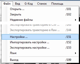
Переход к настройке через меню файл->настройки, рисунок 1
2.1 Настройка осей, рисунок 3, здесь устанавливаем количество осей 3, для станков с поворотной осью 4.
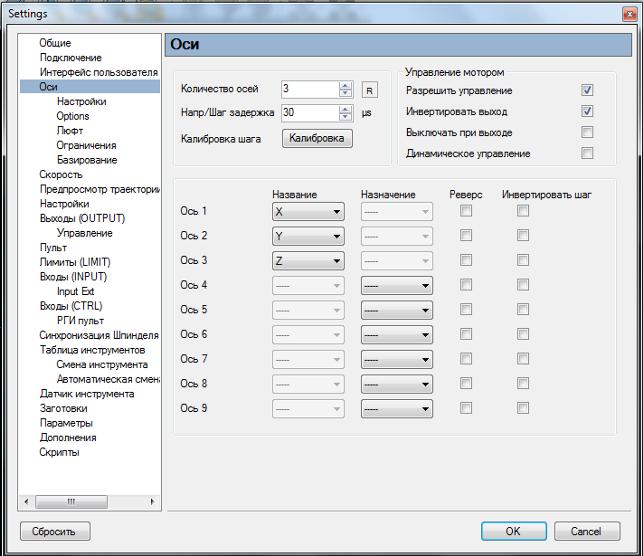
Здесь же, при необходимости, можно изменить направление перемещения по любой оси, установкой галочки в поле «реверс».
Если известен шаг винта и установленный на контроллере микрошаг(коэффициент дробления шага), то можно перейти пропустить пункт 2.2 и продолжить настройку программы с пункта 2.3
2.2 Кнопка «Калибровка» позволяет вычислить величину «Шагов/Еденицу».
Управляя вручную перемещением каретки с инструментом станка, с помощью кнопок «правый Ctrl» + стрелки клавиатуры, выводим каретку примерно на середину.
Выбираем калибруемую ось, рисунок 3
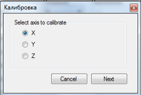
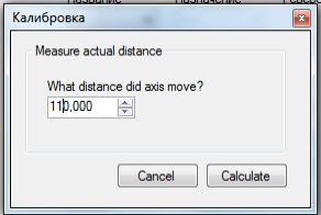
Нажимаем «Next» и указываем расстояние перемещения, рисунок 4.
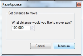
Заносим расстояние на которое переместилась каретка с инструментом, рисунок 5
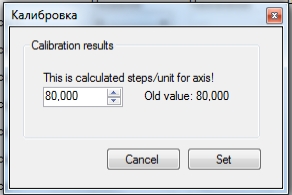
Нажимаем «Calculate» и программа выдаст значение «Шагов/Еденицу». Нажав «Set», программа сохранит эти значения , рисунок 6, и переходим к пункту 2.4
2.3 Установка скоростей холостых перемещений и передаточных чисел.
Меню Файл->Настройки->Оси->Настройки , рисунок 7
Настройка передаточных чисел для определенного ходового винта заносится в поле «Шагов/Еденицу».
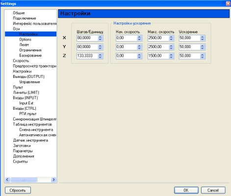
Рисунок 7 Настройка передаточного числа, скорости холостых перемещений и ускорений.
Передаточные числа, скорости и ускорения устанавливаются раздельно для каждой оси,
Передаточное число (для установленного ходового винта ЧПУ станка)
В окошке «Шагов/Еденицу» данные вводятся в соответствии с таблицей для винтовых передач, соединенных напрямую с двигателем, имеющим угол одного шага 1,8 градуса.
Для Моделист2030 c винтом М12 значение «Шагов/Еденицу» устанавливаем равным «228.57142»
Для алюминиевого станка CNC-2020AL 200мм х 200мм c винтом TR10 значение «Шагов/Еденицу» устанавливаем равным «200»
Для Моделист3030 c винтом TR12 значение «Шагов/Еденицу» устанавливаем равным «133.333333»
Для Моделист3040, Моделист4060, Моделист4080 и алюминиевых станков (кроме модели 200мм х 200мм) c ШВП1605 значение «Шагов/Еденицу» устанавливаем равным «80».
Cкорость перемещений ставим не более 3000 для алюминиевых, не более 2500 для станков 3040 и 4060 с ШВП1605, не более 1000 для моделист2020 и 2030, ускорение устанавливаем равным «50», то есть как на картинке, рисунок 7.
Для оси Z значение «Шагов/Еденицу может отличаться от значений других осей.
Устанавливаем для оси Z:
Для Моделист2030 c винтом оси Z М12 значение «Шагов/Еденицу» устанавливаем равным «228,57142»
Для Моделист3030 и станка из алюминия 200мм х 200мм c винтом оси Z TR10 значение «Шагов/Еденицу» устанавливаем равным «200»
Для алюминиевых станков (кроме станка 200мм х 200мм) c винтом оси Z ШВП1605 значение «Шагов/Еденицу» устанавливаем равным «80»
Для Моделист3040-4060-4080 c винтом оси Z TR12 значение «Шагов/Еденицу» устанавливаем равным «133.333333».
2.4 Программные ограничения Меню Файл->Настройки->Оси->Ограничения
3 Описание интерфейса программы CNC USB Controller.
3.1 Главное окно программы, на рисунке 8.
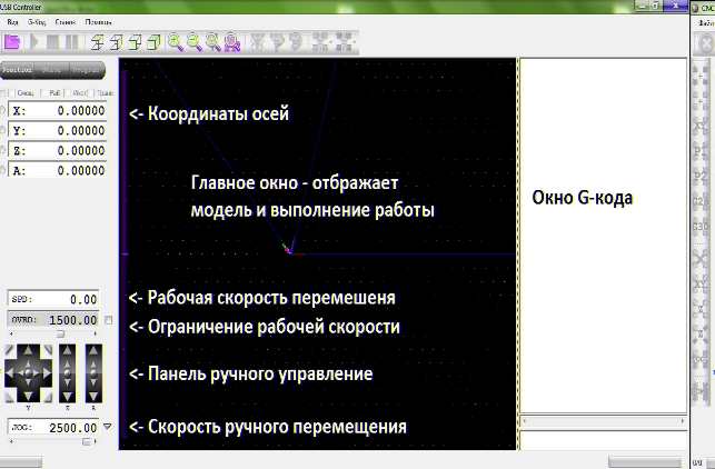
Рисунок 8 Главное окно программы CNC USB Controller.
3.2 Вид рабочей области и окна G-кода, рисунок 9
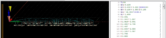
В рабочей области отображается:
сетка, с размерами указанными в настройках,
направление осей XYZ,
жёлтый конус — кончика инструмента (фрезы),
фиолетовый конус — нулевая точка,
голубая полоса — траектория холостого перемещения инструмента,
белая полоса — траектория рабочей подачи инструмента (рабочего хода)
В левой части окна отображается G-код, элементы которого отображаются разными цветами.
3.3 Относительные координаты положения инструмента, рисунок 10.
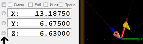
Рисунок 10.
Их модно сбросить разом «Обнулить все координаты», можно по отдельности нажимая на кружок. Так же их можно ввести вручную. Эти действия необходимо провести после перемещения каретки с инструментом в начальное место старта фрезеровки, обычно это левый ближний угол заготовки.
3.4 Панель управления ручным перемещением инструмента.
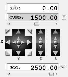
Панель управления
SPD – реальная скорость перемещения в текущий момент
OVRD — ограничение рабочей скорости(скорости подачи)
(если галочка не стоит то ограничения идут максимальные из настроек).
JOG — скорость ручного перемещения.
Большие стрелки перемещают инструмент в указанном направлении, пока они нажаты.
Маленькие стрелки для дискретного перемещения на один шаг, перемещают инструмент на определенное расстояние, указанное в настройках.
3.5 Описание кнопок управления.
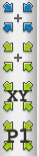
Обнулить все координаты
Переместить в точку 0,0,0
Переместить в точку 0,0,Z не изменяя координаты по Z
Переместить в точку с заданными координатами X, Y, Z
4. Создание управляющей программы(G-кода) по растровому изображению из файлов *.jpg
Файл -> открыть -> выбираем наше изображение.
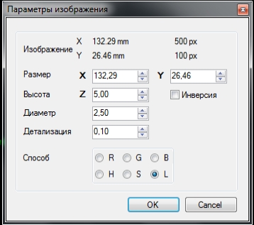
Рисунок 12.
Где:
Размер — общий размер.
Высота — общая высота работы, такой же будет и высота безопасного перемещения.
Диаметр — диаметр инструмента, так же это расстояние между проходами.
Детализация — на сколько срезать вертикальные плоскости.
Инверсия — инверсия изображение.
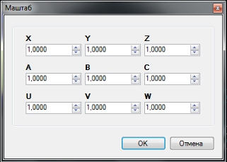
5 Масштабирование.
G-код Маштаб …
Функция «Масштаб» позволяет изменить размер вашей уже загруженной в G-коде модели.
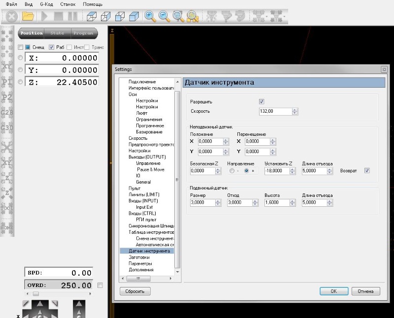
6 Настройка Датчика инструмента (датчик нуля)
6.1 Подключить датчик, один провод на LZ- второй провод на клемму 12В
6.2 Разрешить программе использование датчик а инструмент а.
Для этого в меню Файл/Настройки/ Датчик инструмент а установить галочку «Разрешить», рисунок 14.
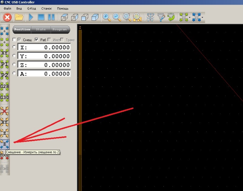
Нажать кнопку «Измерить смещение по Z», рисунок 15, кнопка примет оранжевый цвет, нажать кнопку «смещение — Текущее только Z»(она расположена выше, над кнопкой «Измерить смещение по Z»), снова нажать «Измерить смещение по Z». Станок опустит с заданной скоростью фрезу до касания датчик а и автоматически поднимет инструмент вверх до заданной безопасной высоты.
Статьи по подготовке файлов резки для фрезерного станка в программе ArtCam:
Which CNC Control Software Should I Use?
![]()

CNC is at the heart of the maker community. By using simple tools like CNC mills, laser cutters or routers, you could create anything from stencils to laser-cut jewelry. But did you know that there’s a 3 step process to CNC? Not only do you need to create a vector with CAD, you also need CAM software and CNC control software to bring your project to life. It can be difficult trying to navigate the choppy waters of CNC software, so Scan2CAD has done all the heavy lifting for you.
This handy guide aims to explain what types of software are involved in CNC—from CAD to CAM to CNC control software. We’ve even included examples of top software and freeware that you could be using with your CNC projects. We’ll even show you where you can find free DXF designs to start your own projects.
Table of Contents
CNC: Overview
If you didn’t already know, CNC stands for Computer Numeric Control. CNC machines work by removing material from the initial piece, as opposed to adding new material to it (such as in 3D printing. CNC can be described as a type of subtractive manufacturing and a process such as 3D printing can be described additive manufacturing.
Examples of CNC machines include mills, routers, plasma cutters and laser etchers. For a better look, check out Scan2CAD’s comparison of CNC machines.
Your CNC machine runs on a series of pre-programmed commands. The most common programming language is called G-code, though other languages like Heidenhain and Mazak exist for CNC.
G-code controls the movement of your CNC machine’s tool. It controls its position and depth on the X, Y and Z axes. It also controls the speed at which it rotates and the rate at which it moves.
From Design To Fabrication
Typically, there’s a three step process to CNC that involves three corresponding types of software. To begin, you first need a design in a vector file format (unless you already have the G-code). A vector is a set of mathematical instructions that will dictate how your image is rendered—the most popular vector file format is DXF. You can create your designs and vectors with CAD software. Alternatively, you can use software like Scan2CAD to convert a raster design to a vector.
Once you have your vector, you will need to convert it to G-code which is a programming language that directs your machine. This can be done with CAM software. The process then ends with CNC control software which will read your G-code and turn it into motion to run your CNC machine.

Of course, there are exceptions to the above process. For example, you might find yourself using software that integrates both CAD/CAM capabilities. Or, you might want to skip the CAD step altogether by using free DXFs. We have discussed both possibilities below.
If you’re already sorted with CAD/CAM software, or you’re just hunting for the best control software, skip straight to step 3!
Step 1: CAD Software
Computer Aided Design software is the starting point for most CNC projects—this software is used to create your designs and vectors. There are hundreds of CAD packages available, each with different capabilities depending on which industry you’re interested in. As we have covered before, CAD is widespread across hundreds of industries—from architecture to art to mechanics.
Of course, you need to choose your CAD program carefully. These packages can be expensive, so you’ll want to make sure you’re going to get your money’s worth—so take advantage of free trials and look at reviews. Unfortunately, there can be a steep learning curve for many packages—however, there are online resources that can help you along the way. For example, Scan2CAD offers tips and tricks for AutoCAD and SolidWorks.
For a better look, take a look at the following list of popular CAD software and freeware below.
Popular CAD Software

Screenshot of AutoCAD 2013
- AutoCAD: used to create 2D and 3D drawings. It spans across industries including mechanics, architecture and civil engineering. It’s one of the most popular CAD packages in the world.
- SolidWorks: a parametric feature-based 3D modeling software. It can be used for advanced 3D modeling and auto-generated 2D drawings. It’s the most popular parametric modeler.
- Rhino3D: can create, edit and render NURBS curves, surfaces, solids and polygon meshes. It includes free-form 3D modeling tools alongside complete accuracy and accessibility.
This list of course, is just the tip of the iceberg. If you’re looking to branch out into cloud-based CAD for example, you might like to try a package like Onshape. You should also bear in mind that some CAD packages offer CAM capabilities. Fusion 360 for example, includes built-in CAM software that allows you to create and edit G-code.
Free CAD Software
If you’re not looking to fork out money for a CAD package, you might find it more worthwhile to try out free CAD packages. This is a preferred option for many CNC hobbyists who don’t use CAD software enough to warrant paying a large expense.

Screenshot of Wings3D
- Google Sketchup: it’s not technically a CAD program, but it does allow you to produce 3D drawings that you can use with a CAM program to create G-code.
- Wings3D: a modeling tool designed primarily for the creation of 3D models, which can then be imported into a CAM program. It supports mesh tools, design and editing features etc.
- NanoCAD: offers 2D, 3D and parametric design—you can build anything from machine parts to blueprints. It’s free, but there are premium versions which include add-on features.
If that’s not enough for you, check out our list of top CAD freeware.
You might be wondering if there’s a way to avoid CAD software altogether. If that’s the case, you’re in luck—you can access free DXFs that are ready-to-cut so you don’t have to design anything. Take a look below to see how.
Free DXF Designs
 If you’re looking to start an exciting project from one of Scan2CAD’s CNC project ideas, you might not want to go through the process of creating your own image—it can be pretty time-consuming after all. If that’s the case, you might want to consider using ready-to-cut DXF designs.
There’s a wide variety of free DXF websites that you can download DXFs from to get started on your own CNC project. These include:
A problem you might have with these sites however, is that they will only offer you a finite source—they’re only updated once a month or so. That’s where Scan2CAD comes in!
Scan2CAD isn’t just a conversion software, it’s also a great source for anything CAD, CAM and CNC-related. It’s not surprising then, that we offer our own cut-ready CNC designs that are free and ready to use with your CNC machines. And it’s not just one or two designs—it’s an entire DXF pack every single week—typically containing 6 or 7 designs in a DXF and JPG format.
The theme for each week changes, so you’ll be sure to find something to your taste. Our previous packs have included Ornamental Patterns and American Football. So if you’re looking for a new project to start each week, subscribe today and get DXF packs sent straight to your email.

Step 2: CAM Software
Computer Aided Manufacturing software is fed your CAD drawing and subsequently produces G-code that you can then feed into your control software to run your CNC machine. It is possible to write G-code by hand for simple circles or lines, but it’s much easier to produce using a CAM program. If you’re still not sure what G-code is, head on over to Scan2CAD’s exclusive guide to G-code.
As we have discussed, there can be confusion as to the difference between CAD and CAM, as many packages like Fusion 360 come with both capabilities nowadays. While it can be more efficient to have an integrated solution, it can be more expensive, which is problematic if you’re looking for a cost-effective package.
Popular CAM Software

Screenshot of MechCAM. Image source: MeshCAM
- MeshCAM: works with almost every 3D CAD program by opening the two most common file formats, STL and DXF. It boasts more toolpath options than any competing CAM program.
- MasterCAM: one of the most popular CAM programs available. It provides full 3D live wireframe modeling, and a broad range of translators allowing you to open any CAD file.
- OneCNC: provides a CAM system for milling, turning and mill-turn machining. It has versions that provides a range of capabilities in 2, 3, 4 and 5 axis machining.
Free CAM Software
If you’re a casual CNC hobbyist or beginner, you might not need to use the most powerful CAM packages available. After all, you won’t need to figure out 6-axis toolpaths on your first day! With that in mind, the following free packages might be more to your level.

Screenshot of FreeMILL. Image source: MecSoft
- PyCAM: a toolpath generator for 3-axis CNC machining. It loads 3D models in an STL format, or 2D contour models from DXF or SVG files. You can then use the resulting G-code with any machine controller.
- FreeMILL: a free milling module for programming CNC mills and routers. You can run full simulations on your part models and output G-code to your machine.
- G-Simple: is a simple CAM package for 3-axis machining centers. It includes a tools and materials library, along with a selectable excess material removal filter.
Of course, you should bear in mind to be careful when using freeware. Only use freeware that has been reviewed by reliable sources—you don’t want to accidentally download malware. As we have discussed previously with the pitfalls of online converters, freeware can often cause more problems than it’s worth.
Now you’ve had a look at CAD and CAM packages, you might be wondering about packages that integrate both capabilities—or even how you can speed up the entire process. That’s where Scan2CAD comes in once more! Check out step 2.5 below to find out how you can load or create vectors, and convert them to G-code in one single package!
Step 2.5: Scan2CAD
Scan2CAD is a market-leading raster-to-vector conversion software. It supports no fewer than 33 file types, and comes with batch processing, flexible licensing and 24/7 support.
With it, you can convert your raster designs to a vector file format in a matter of seconds. You can then make use of raster and vector editing suites to create the most optimal vector image you can use for your CNC design. And the best part is, it only takes a matter of seconds. Don’t believe us? Take a look at the animation below to see it in action!

In this animation we convert an anchor image to a vector outline for CNC using Scan2CAD
For more information, check out Scan2CAD’s top tips for taking your design to CNC fabrication.
And that’s not all! Scan2CAD isn’t just useful for converting your files to a vector file format, it can also be used for CAM applications. Once you have a vector you’re happy with (whether it’s one you’ve converted or a ready-to-cut design), you can use Scan2CAD to export it directly to a G-code compatible format. Scan2CAD currently supports three of the most popular G-code file types including: .CNC, .NC, and .TAP.
Scan2CAD also provides a range of options in its CNC Export dialog box, which include:
- G-code Bezier options: cubic splines (G-code G05), arcs (G-code G02/G03) or polylines (G-code G01).
- Arc and circle rotation: clockwise or anti-clockwise.
- Z-settings: various parameters relating to the cutting of the exported vectors.
- Scale settings: the relation between vector points and a distance in real life, e.g. two points on a vector image could represent an inch.
Want a more in-depth look? Take at how to convert an image for CNC with Scan2CAD.
CONVERT YOUR DESIGNS FOR CNC
Scan2CAD is the market leading conversion software for CAD & CNC.
Step 3: Machine Control Software
Generally speaking, there are two types of CNC control software: control software built into your machine, and PC-based software. If you were using a commercial CNC machine like HAAS Vertical Machining Center, you would get a complete hardware and software solution that is built into the machine—you’d be able to transfer your G-code directly to the machine. Hobby CNC machines by comparison, have an external controller—by making use of control software, you can turn your PC into a machine controller.
When it comes to PC-based controller software, there’s a wide variety on offer. There are a few key controllers that stand out from the crowd however. Take a look below for our top picks, featuring low-cost and free software.
1. The Mach Series

- Cost: $200 (Mach4)
- Controls: mills, lathes, routers, lasers, plasma etc.
- Operating system: Windows
The Mach series are at the forefront of CNC control software. The developer ArtSoft has been releasing and improving upon the Mach series for the past decade—the most current version of which is Mach4. This low-cost software works on most Windows PCs, making use of advanced system level drivers to enact pulse timing for stepper motors and step-servo systems.
The software itself is very intuitive and customizable. It can control up to 6 axes of a CNC machine. Previous versions like Mach3 allowed hobbyists to use their license across multiple machines, whereas Mach4 now ties the license to a specific PC. If you are curious about the software, you can test out the free demo mode for up to 500 lines of G-code!
2. LinuxCNC

- Cost: Free
- Controls: mills, lathes, 3D printers, robot arms etc.
- Operating system: Linux
LinuxCNC is undoubtedly the direct competitor to the Mach series—it’s certainly a popular option for many CNC hobbyists, and not just because it’s free! Previously called EMC2, this CNC control software is completely open source. And as the name suggests, the software runs under Linux. Due to the need of precise real time control of machines in motion, the software requires a platform with real-time computing capabilities. This means that if you don’t have real time computing capabilities, your PC will only run the package in demo mode.
Freeware can often seem lacking in some way, however that certainly isn’t the case when it comes to LinuxCNC. It can control up to 9 axes of a CNC machine, and has several GUIs suited to specific types of usage such as touch screen and interactive development. The software also supports advanced control features like rigid tapping and cutter compensation.
3. TurboCNC

- Cost: $60
- Controls: mills, lathes, routers, laser cutters etc.
- Operating system: DOS
Our final choice for top CNC control software is TurboCNC. This machine control software provided by Dak Engineering runs under DOS. The software itself is shareware—you can gain access to its source code and free support for a low-cost fee of $60.
TurboCNC is an efficient controller that runs stepper motors and step-servos. It can control up to 8 axes of motion, and it comes with configurable I/O for reversible and speed control spindles. It also provides fully parametric programming with variables, subroutines and expressions.
4. Universal Gcode Sender
Universal Gcode Sender (UGS) is the software of choice by a large number of the CNC community. This in-part might be because the software is absolutely free and available on Github.
The software has been designed with real-world problems in mind. It comes with ‘configurable gcode optimization’ to remove comments, convert arcs to lines segments, remove whitespaces and more.
- Cost: Free!
- Controls: mills, lathes, routers, laser cutters etc.
- Operating system: Cross platform, tested on Windows, OSX, Linux, and Raspberry Pi.
Other CNC control software includes:
If you want to learn more about the world of CNC, why not check out the CNC section of the Scan2CAD blog? We cover a range of topics from the best CNC kits for beginners to new innovations in CNC.


