- Создание драйверов. Часть 5. Фильтр драйвер
- Creating a New Filter Driver
- Case 1: The documentation for your technology recommends UMDF.
- Case 2: The documentation for your technology recommends KMDF.
- Case 3: The documentation for your technology describes a specific filter or mini filter model.
- Case 4: The documentation for your technology recommends WDM.
- Case 5: The documentation for your technology does not have a recommendation for a filter driver model.
- Device filter driver ordering
- The need for device filter driver ordering
- Implementing device filter driver ordering
- Scenarios
- Default filter level
- Syntax
- Registering filters
- Defining Filter Levels
- Legacy-equivalent filter registration
Создание драйверов. Часть 5. Фильтр драйвер
В этой части цикла статей, рассматривается создание и тестирование фильтр драйвера – это драйвер, основной функцией которого является обработка проходящих через него IRP пакетов, это возможно благодаря многоуровневой модели драйверов Windows, где несколько драйверов можно выстроить в одну цепочку, соответственно добавляя новые возможности нижележащему драйверу.
Это может быть шифрование данных, форматирование данных, обработка ошибок, вплоть до уничтожения информации или ее логирования и скрытия.
Передача и обработка запросов ввода/вывода производится в виде пакетов IRP, которые формирует диспетчер ввода/вывода, находящийся в ядре Windows, где для каждого драйвера выделяется своя собственная структура стека IRP, то есть если в цепочке находится три драйвера, то пакет будет иметь в своей структуре стека три указателя на IO_STACK_LOCATION, для каждого драйвера. Схематически многоуровневая модель показана на рисунке: 
В качестве устройства-цели к которому мы будем добавлять наш фильтр драйвер, выступит \Device\Beep, это устройство которое отвечает за работу системного динамика. Драйвер фильтр должен обрабатывать те же самые функции, что драйвер находящийся ниже его, а также должен иметь одинаковые флаги создаваемого объекта устройства. Ниже приводится код драйвера фильтра и пояснения:
PDEVICE_OBJECT pdDevObjTarg; — глобальная переменная для хранения указателя на устройство находящееся ниже фильтра.
PFILE_OBJECT FileObj = NULL; — переменная для хранения указателя на объект-файл, для выгрузки нижележащего драйвера.
for(i=0; i MajorFunction[i] = DispatchPass;
>
В примере мы делаем одну точку входа в драйвер для всех рабочих процедур драйвера, выглядит она вот так:
NTSTATUS DispatchPass(IN PDEVICE_OBJECT fdo, IN PIRP irp)
<
PIO_STACK_LOCATION IrpStack = IoGetCurrentIrpStackLocation(irp);
if(IrpStack->MajorFunction == IRP_MJ_DEVICE_CONTROL)
<
DbgPrint(«-IOCTL-«);
IoSkipCurrentIrpStackLocation(irp);
return IoCallDriver(pdDevObjTarg,irp);
>
где мы просто получаем указатель на текущий стек IRP пакета, и если к драйверу обратились при помощи функции DeviceIoControl, то мы отлавливаем код рабочей процедуры и выводим сообщение.
IoSkipCurrentIrpStackLocation(irp);
return IoCallDriver(pdDevObjTarg,irp);
здесь фильтр просто пропускает пакеты без модификаций.
status = IoCreateDevice(DriverObject,sizeof(PDEVICE_OBJECT),NULL,FILE_DEVICE_BEEP,0,FALSE,&fdo);
if(!NT_SUCCESS(status))return status;
fdo->Flags |= 0x44;
Создаем безымянное устройство и не имеющее символьной ссылки, и добавляем флаги как у нижележащего устройства.
RtlInitUnicodeString(&devName,L»\\Device\\Beep»);
Копируем строку с именем устройства к которому хотим присоединить наш фильтр.
status = IoGetDeviceObjectPointer(&devName,STANDARD_RIGHTS_ALL,&FileObj,&pdDevObjTarg);
if(!NT_SUCCESS(status))return status;
получаем указатель на объект-устройство нижележащего драйвера.
IoAttachDeviceToDeviceStack(fdo,pdDevObjTarg);
if(!NT_SUCCESS(status))return status;
подключаем наш фильтр к устройству.
VOID FilterDriverUnload(IN PDRIVER_OBJECT fdo)
<
IoDetachDevice(pdDevObjTarg);
ObDereferenceObject(FileObj);
IoDeleteDevice(fdo->DeviceObject);
>
Функция выгрузки драйвера, в которой удаляется из стека фильтр, удаляется объект-файл и сам фильтр.
Код программы запуска драйвера:
Когда программа запуска драйвера запущена и находится в режиме паузы, то можно увидеть что фильтр присоединился к устройству: 

И теперь достаточно запустить любую программу, которая будет вызывать функцию Beep, например такую:
Сразу становится видно, что идет фильтровка кода IRP_MJ_DEVICE_CONTROL: 
Creating a New Filter Driver
In this topic we explain how to use Visual Studio to start writing a new filter driver. Filter drivers are different from device function drivers, software drivers, and file system drivers, which we cover in other topics. To learn about filter drivers and how they differ from other types of drivers, see the following topics.
To begin, first determine which driver model is appropriate for your filter driver. For help determining which model is best for you, see Choosing a Driver Model. If you are writing a filter driver for a hardware device, determine where your device fits in the list of technologies described in Device and Driver Technologies. See the documentation for that particular technology to see whether there is any guidance for choosing a filter driver model. The recommended filter driver model varies from one technology to the next. For some technologies, the documentation recommends using the User Mode Driver Framework (UMDF), the Kernel Mode Driver Framework (KMDF), or the Windows Driver Model (WDM). For other technologies, the documentation gives explicit details on how to write a filter driver. Some technologies have mini filter models. For some technologies, there might not be any recommendation for a filter driver model.
Next, determine which of the following cases describes your driver model recommendation and follow the steps:
Case 1: The documentation for your technology recommends UMDF.
- In Visual Studio, on the File menu, choose New | Project.
- In the New Project dialog box, in the left pane, locate and select Visual C++ | Windows Driver | WDF.
- In the middle pane, select User Mode Driver (UMDF).
- Fill in the Name and Location boxes, and select OK. For more information, see Writing a UMDF Driver Based on a Template. NoteВ В When you create a new UMDF driver, you must select a driver name that has 32 characters or less. This length limit is defined in wdfglobals.h.
- At this point, you have a driver project that implements the general code required by most UMDF drivers. Now you can supply the code that is specific to your filter.
Case 2: The documentation for your technology recommends KMDF.
- In Visual Studio, on the File menu, choose New | Project.
- In the New Project dialog box, in the left pane, locate and select WDF.
- In the middle pane, select Kernel Mode Driver (KMDF).
- Fill in the Name and Location boxes, and select OK. For more information, see Writing a KMDF Driver Based on a Template. NoteВ В When you create a new KMDF driver, you must select a driver name that has 32 characters or less. This length limit is defined in wdfglobals.h.
- At this point, you have a driver project that implements the general code required by most KMDF drivers. Now you can supply the code that is specific to your filter.
Case 3: The documentation for your technology describes a specific filter or mini filter model.
If your device technology has a specific filter or minifilter model, check to see if Visual Studio has a template for the model.
- In Visual Studio, on the File menu, choose New | Project.
- In the New Project dialog box, in the left pane, locate and select Templates | Visual C++ | Windows Driver.
- Browse the list of installed templates to see whether there is a template for the type of filter you need to write. For example, you might choose the Filter Driver: NDIS template under Networking.
- If there is no template for your type of filter driver under Windows Driver, select Online and browse the templates that are available online.
- If you find a template for your type of filter driver, select the template, fill in the Name and Location boxes, and select OK.
- At this point, you have a driver project that implements the general code required by your filter driver. Now you can supply the code that is specific to your filter. Refer to the documentation for your technology to learn about the functions that you need to implement.
If your device technology has a specific filter model or a minifilter model, and you can’t find a template for your type of filter driver, refer to your technology-specific documentation for guidance to determine whether to use UMDF, KMDF, or WDM.
Case 4: The documentation for your technology recommends WDM.
In Visual Studio, on the File menu, choose New | Project.
In Visual Studio, in the New Project dialog box, under Windows Driver, select WDM.
Fill in the Name and Location boxes, and select OK.
At this point, you have an empty WDM driver project. In the Solution Explorer window, select and hold (or right-click) your driver project, and choose Add | New Item.
In the Add New Item dialog box, select C++ File (.cpp), enter a name for your file, and select OK.
NoteВ В If you want to create a .c file instead of a .cpp file, enter a name that has the .c extension.
Implement the functions required by your filter. As you implement and organize your functions, you might decide to add additional .cpp or .c files.
Case 5: The documentation for your technology does not have a recommendation for a filter driver model.
Determine whether UMDF, KMDF, or WDM is the best model for your filter driver. For help, see Choosing a Driver Model.
In Visual Studio, on the File menu, choose New | Project.
In Visual Studio, in the New Project dialog box, under Windows Driver, select one of the following templates:
- WDF | User Mode Driver (UMDF)
- WDF | Kernel Mode Driver (KMDF)
- WDM | Empty Kernel Driver
NoteВ В When you create a new KMDF or UMDF driver, you must select a driver name that has 32 characters or less. This length limit is defined in wdfglobals.h.
Implement the functions required by your filter. Create new .c or .cpp files as needed.
If you are not sure which template to use, consider reading or posting to the Windows Hardware WDK and Driver Development forum.
Device filter driver ordering
Microsoft has developed a method of declaratively adding filters by expressing the intent of the filter, rather than the stack position, known as device filter driver ordering.
The need for device filter driver ordering
Prior to Windows 10 version 1903, the only supported way to register a device filter driver was by addition of a registry entry (using the AddReg directive). However, this method of registry manipulation does not provide the flexibility to specify at exactly which position to register a particular filter.
Filter registration using the AddReg directive simply appends the filter to the end of the filter list. This approach uses a list of values where order matters and determines where in the stack the filter is loaded.
Using a single list of ordered values is less than ideal, especially when AddReg only appends to the end, because there are negative consequences when more than one driver is adding filters to the same device.
In the scenario where there is at least one Extension INF involved, if the INFs improperly use AddReg (in other words don’t use the append flag), they could wipe out a filter added by a different INF.
Additionally, multiple Extension INF’s could be adding filters, and the relative ordering of those filters may be important; however, the Plug and Play (PnP) platform does not guarantee an installation order for the extensions. The result is that the order of the «appends» is not guaranteed.
Implementing device filter driver ordering
In order to provide a flexible declarative method to register device filters, Microsoft has developed a method of declaratively adding filters by expressing the intent of the filter, rather than the stack position. The solution provides function driver authors the ability to express in their INF an ordered set of positions (called levels) that a filter may register itself against.
In addition to a specific level, a filter can declaratively register simply as an upper or lower level filter.
The infrastructure is based on a new filter registration method to determine what order drivers are to be included in the device stack. The new method does not break compatibility for the old way of adding filters. It does, however, enable new filters to move to a more robust and flexible registration mechanism.
The method is enabled by having the base INF define an ordered list of one or more «levels». Both the base INF and any extension INFs may register a declarative filter via a new INF directive that specifies the service name and level to which the filter belongs to. Upper and lower filters each are represented by their own respective ordered list of levels.
These upper and lower filter lists are created by sorting all filter drivers by their level. The order of the filters within each level should be considered arbitrary, where no dependency may be taken on the order of filters within a particular level. In scenarios where the relative order of two filters must be guaranteed, they should be registered to different levels.
Consider the following device driver example:
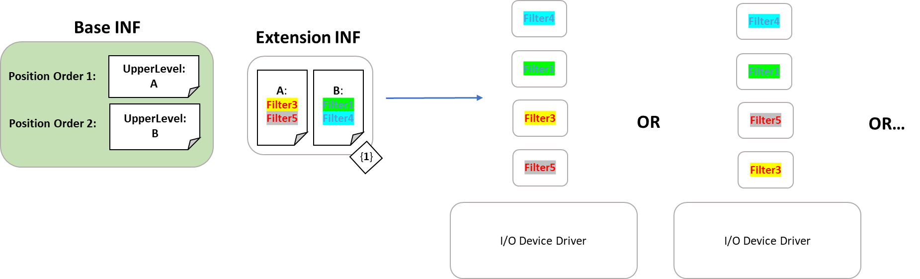
The device driver’s base INF declares two upper filter levels, A and B (in that order). In the base INF’s associated Extension INF, two filters are added into each of the two levels.
The result of the installation of the device driver is a device stack order that merges the lists of filter drivers while respecting the desired positioning and ordering. The resulting device stack order ensures that any filter placed in the «A» level comes before any filter in the «B» level. However, within each level, the order is arbitrary.
As shown in the example, Filter3 could come before Filter5 or it could come after Filter5. In any case, Filter3 and Filter5 will come before the filters at the next level, «B».
When designing the series of levels that filters can be registered against, rather than creating a series of levels for the sake of ordering, the levels should be named and ordered such that they map to the intent of the filter. For instance, an I/O device may define the level Encryption, to which any encryption filter should be registered. This allows the intent of the filter to be easily understood and managed, and makes the stack more robust against breaking changes to the function driver.
Even without levels defined by the base INF, a declarative filter may register as simply upper or lower. When levels are not defined, this is logically equivalent to appending the filter to the end of the UpperFilters/LowerFilters registry value. When levels are defined, one of the levels must be marked as the default level in the base driver, and in this case the filter will be registered into that level.
Scenarios
Consider an I/O device driver that encrypts the data that is coming through the stack. A typical implementation may use a lower filter driver immediately underneath the function driver to accomplish this. In order to ensure that the encryption filter is placed at the exact position the driver author desires, they may use declarative filters as shown below:
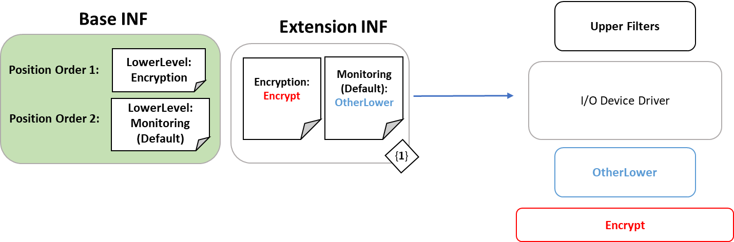
The Base INF establishes two levels of lower filters, «Encryption» and «Monitoring» (Default). «Monitoring» (Default) in this example are the rest of the lower filters that might exist for this particular device. By explicitly placing the «Encrypt» filter driver in the «Encryption» level, the driver ensures that the resulting device stack order will put the «Encrypt» filter driver before any other lower filters and immediately following the function driver.
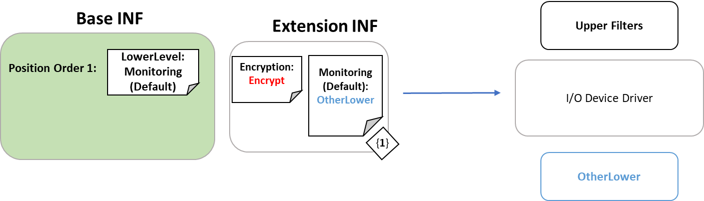
Let’s take the example one step further. Imagine a newer version of the driver comes out and the author has built in encryption to the function driver. This removes the need for a separate «Encrypt» filter driver. The author simply needs to remove the level that contained the «Encrypt» filter from the Base INF and when the driver updates, the stack is dynamically built again.
If a filter declares itself to be in an explicit level that does not exist, the filter does not end up in the device stack. In the example, the Base INF has been updated and even though the Extension INF remains the same, the resulting device stack excludes the «Encrypt» filter as it was not included in the Base INF’s declaration of levels.
Default filter level
To generate the final filter stack, all sources of filter information are merged into a single list. It is important to note that the merge logic is performed when creating the device stack. If a new filter is added by installing a new/updated base or extension driver, the devices will be restarted during installation and pick up a new filter list.
Some sources of filters lack any position information, namely filters added via the legacy UpperFilters/LowerFilters registry values, or through position-only declarative syntax (discussed below).
To support an effective merge when lacking position information, an additional piece of information must be defined by the Base INF: a default filter level. The default filter level is a position where filters, lacking level or position information, will be inserted.
For example, filter levels may be defined in the Base INF as:
Specifying the default level as the final level indicates that any filter that lacking position information will be appended to the filter list. Alternatively, the driver author may wish to have the stack always end with filters explicitly registered to level C:
Due to the default filter level being set to B, any additional filter without position information will be inserted between A’s filters and C’s filters.
Syntax
Registering filters
FilterLevel OR FilterPosition may be specified in one of two ways:
Option 1:
Option 2:
This can be done in both Base and Extension INF’s.
FilterName is the name of the service on the system.
Flags is currently unused and should be left empty or set to 0.
FilterSection is a section describing the filter.
A filter section must contain exactly one of the following two directives:В FilterLevel or FilterPosition.
A FilterLevel is a specific place to insert the device filter on the stack, defined by the Base INF.В Within each level, the order of the filters is arbitrary.
A FilterPosition is used in the case where the class has one specific place for third-party filters to be inserted.
Defining Filter Levels
This can only be done by a base driver.
The full declarative list of filters for a specific device can be retrieved by querying the following properties:
Legacy-equivalent filter registration
Let’s examine how to accomplish the legacy approach of trying to add an upper filter via INF:
This syntax will add «MyFilter» to the end of the list of upper filters.
With the new syntax that has been introduced, the above section is logically similar to:
This specifies that the filter «MyFilter» should be added to the list of upper filters. If the base INF has specified filter levels, using FilterPosition will register the filter in the default level for that position.
If filter levels are not specified, this filter will be registered as an upper filter in arbitrary order.


