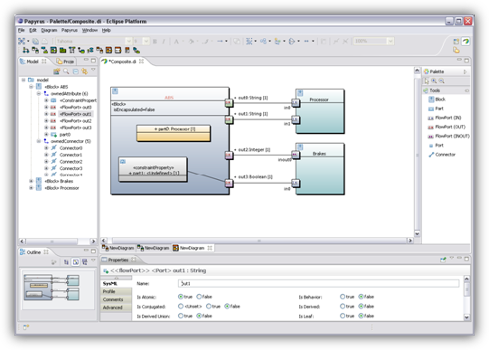
- Eclipse Papyrus ™ Modeling environment
- Downloads
- There are four ways to install Eclipse Papyrus for Real Time (Papyrus-RT):
- Current release: Papyrus-RT 1.0.0 on Eclipse Oxygen (Recommended)
- Papyrus-RT all-in-one RCP
- Papyrus-RT Installer
- Eclipse Installer
- Update sites
- Older releases
- Papyrus-RT 0.9.0
- Papyrus-RT all-in-one RCP
- Papyrus-RT Installer
- Update sites
- Nightly builds
- Eclipse Papyrus ™ Modeling environment
- Papyrus/Papyrus Developer Guide
- Contents
- Development Environment
- Java Version
- Downloading Eclipse
- Papyrus Oomph Setup Model
- Installation Details
- Additional Useful Tools
- Configuration
- Gerrit Configuration
- API Management Configuration
- Apply Papyrus Configuration Files
- How To .
- Clone Papyrus Git Repository
- Getting Started with Papyrus UMLLight
- Contents
- Introduction
- Target audience
- Papyrus UMLLight personae.
- What this tutorial is and is not
- Goals
- Papyrus and Papyrus UMLLight
- What is Papyrus
- What is the Unified Modeling Language (UML)
- What is a UML model
- What is a UML diagram
- What is Papyrus UMLLight
- Comparing Papyrus and Papyrus UMLLight Diagram Support
- Installing Papyrus UMLLight
- Starting Papyrus UMLLight
- About Workspaces
- Palettes
- Palette Structure
- Customized Palettes
- Diagram Palettes
- Online Shopping System (OSS) Project Overview
- Use Case Modeling
- Basic Use Case Diagram Concepts
- Creating the OSS Use Case model
- Create and initialize the OSS Project
- What was created
- The project Explorer
- The Model Explorer
- The workspace is now ready for the creation of the use case model
- Populate the OSS Use Case Diagram
- Complete the use case diagram
- Documentation View
- Adding documentation to a use case
- Example of the documentation view.
- Use Case Analysis
- What do we mean by «Use Case Analysis»?
- Using Class diagrams
- Role of Class Diagrams
- Creating a class diagram for the shopping Cart
- Using activity and Sequence Diagrams
- Activity Diagrams
- Role of Activity diagrams
- Basic Activity Diagram Concepts
- Creating an activity diagram for a customer purchase
- Sequence Diagrams
- Basic Sequence Diagram Concepts
- Creating a sequence diagram for a Customer Login
- State Machine Diagrams
- Role of State Machine Diagrams
- Basic State Machine Diagram Concepts
- Adding Structure to models
- Package Diagram
- Creating the package diagram
Eclipse Papyrus ™
Modeling environment
SysML 1.6 for eclipse 2021-09 release is now available! Go to the Market Place or use the update site to install it.
The Eclipse Papyrus 5.2.0 2021-09 release is now available! Go to the Download page to install it as an update site or a zip archive. The associated RCP is available from the RCP download page as well.
It is now possible to associate model explorer customizations to the architecture framework. Papyrus now requires Java 11 to run along with the 2020-12 eclipse releases and has trimmed down the number of re-exported bundles. Note that most of the ‘relatives’: Sysml 1.4, 1.6, Moka, designer. have also been made compatible with the new re-exports and the Java 11 migration. You can download the new release from the Download page to install it from an update site or a zip archive. The associated RCP is available from the RCP download page as well.
We will now begin to work on the next major release of Papyrus (5.0.0) in order to allow us some API changes and other corrections. This version will be available in time to integrate the 2020-12 release train. Because we need to focus on this goal, there is no release planned for the 2020-09 train. The 5.0.0 release will contain, for example, the refactoring of some dependencies such as removing the reexports wherever possible and removing deprecated APIs lingering for far too long in the code base. We will inform you about any work undertaken on the wiki page Incoming work for 2020-12.
The Eclipse Papyrus 4.8.0 2020-06 release is now available! Go to the Download page to install it as an update site or a zip archive. The associated RCP is available from the RCP download page as well.


 Papyrus is now a desirable and robust UML modeling tool which is industry ready.
Ronan Barrett, Senior Specialist at Ericsson
Источник
Downloads
All downloads are provided under the terms and conditions of the Eclipse Foundation Software User Agreement unless otherwise specified.

There are four ways to install Eclipse Papyrus for Real Time (Papyrus-RT):
- Install the Papyrus-RT RCP
The RCP is an all-inclusive self-contained archive (zip) of Papyrus-RT- Pros: Simple three-step installation: download, extract, start working with Papyrus-RT! All dependencies are included.
- Cons: Larger file to download. No bundle sharing.
- Using the Papyrus-RT Installer
The Papyrus-RT installer is powered by Oomph, the same technology used by the Eclipse Installer.- Pros: All dependencies are automatically installed. Support for bundle pooling (saves disk space), managed workspaces, and automatic updates.
- Cons: You have to answers a few simple questions.
- Using the Eclipse Installer
This approach is similar to the Papyrus-RT installer above but it is based on the base Eclipse Installer.- Pros: Increased control of what will be part of the installation, including other Eclipse projects.
- Cons: Increased complexity in the installation process with boxes to check and more questions to answer.
- Manual installation using update sites
This approach is for the Eclipse veterans who are familiar with installing features and plugins in Eclipse, understand what we mean by «p2», and need to install Papyrus-RT with other Eclipse projects.- Pros: Full control of what will be part of the installation, including other projects.
- Cons: Increased complexity in the installation process. Dependencies must be installed separately.
Current release: Papyrus-RT 1.0.0 on Eclipse Oxygen (Recommended)
Papyrus-RT all-in-one RCP
Download one of the packages below for your operating system, and follow the following instructions: Installing the Papyrus-RT RCP.
- Linux (Gzipped Tar file; 353MB)
- Windows (Zip file; 355MB)
- macOS (Zip file; 355MB)
Papyrus-RT Installer
Download one of the packages below for your operating system, and follow the following instructions: Installing Papyrus-RT using the Papyrus-RT Installer.
- Linux (Gzipped Tar file; 48MB)
- Windows (Self-extracting exe file; 49MB)
- macOS (Zip file; 49MB)
Eclipse Installer
Download the Eclipse installer from the Eclipse Installer Wiki or from the Eclipse downloads page and follow the following instructions: Installing Papyrus for Real Time using the Eclipse Installer.
Update sites
Note: If you follow this approach, you will have to manually install dependencies.
Install some Eclipse platform from the Eclipse downloads page, and, using the update site link below, follow the following instructions: Installing new software.
- Release 1.0.0 update site: http://download.eclipse.org/papyrus-rt/updates/releases/oxygen/1.0.0/
Older releases
Papyrus-RT 0.9.0
Papyrus-RT all-in-one RCP
- Linux (Zip file; 304MB)
- Windows (Zip file; 305MB)
- macOS (Gzipped Tar file; 303MB)
Papyrus-RT Installer
- Linux (Gzipped Tar file; 47MB)
- Windows (Self-extracting exe file; 48MB)
- macOS (Zip file; 48MB)
Update sites
Nightly builds
Please keep in mind that this is the head development version!
It might be unstable and contain any kind of errors.
Источник
Eclipse Papyrus ™
Modeling environment
SysML 1.6 for eclipse 2021-09 release is now available! Go to the Market Place or use the update site to install it.
The Eclipse Papyrus 5.2.0 2021-09 release is now available! Go to the Download page to install it as an update site or a zip archive. The associated RCP is available from the RCP download page as well.
It is now possible to associate model explorer customizations to the architecture framework. Papyrus now requires Java 11 to run along with the 2020-12 eclipse releases and has trimmed down the number of re-exported bundles. Note that most of the ‘relatives’: Sysml 1.4, 1.6, Moka, designer. have also been made compatible with the new re-exports and the Java 11 migration. You can download the new release from the Download page to install it from an update site or a zip archive. The associated RCP is available from the RCP download page as well.
We will now begin to work on the next major release of Papyrus (5.0.0) in order to allow us some API changes and other corrections. This version will be available in time to integrate the 2020-12 release train. Because we need to focus on this goal, there is no release planned for the 2020-09 train. The 5.0.0 release will contain, for example, the refactoring of some dependencies such as removing the reexports wherever possible and removing deprecated APIs lingering for far too long in the code base. We will inform you about any work undertaken on the wiki page Incoming work for 2020-12.
The Eclipse Papyrus 4.8.0 2020-06 release is now available! Go to the Download page to install it as an update site or a zip archive. The associated RCP is available from the RCP download page as well.
I use Papyrus both for my research developments and for my teaching courses on UML or SysML.
Jean-Michel Bruel, Professor, IRIT/University of Toulouse, France
Источник
Papyrus/Papyrus Developer Guide
Contents
Development Environment
To ease the development of Papyrus, each member of the team works with basically the same configuration. There are two ways to get your development environment:
- downloading and installing Eclipse
- using the Eclipse Installer (by Oomph) to manage your Papyrus development workbench.
Java Version
OpenJDK 11 (or higher) is recommended.
Downloading Eclipse
You can download a fresh Eclipse Package release on this page. We advise you to download the Eclipse Committer version.
Papyrus Oomph Setup Model
The Eclipse Installer provides a set-up model for Papyrus, making it easier than ever to get a complete Eclipse workbench up and running for development on the Papyrus source code. Just download the Oomph Installer from the linked wiki page and follow the simple wizard to create your IDE and import the Papyrus source projects that you want to work on.
Pick any product you like on the first page, but be sure it’s the latest release of that product for the Papyrus stream you’re working on. For example, if you’re working on the Luna service stream of Papyrus, you need the Luna release of Eclipse. On the second page, expand Eclipse.org / Papyrus to see the various components that you can import to work on. Pick any combination of the leaf-level sub-(sub-)projects, even all of them if you like. In the third page where you specify variables such as install location, workspace location, git clone, etc. be sure to choose «Luna» for the Target Platform. This ensures that you will be set up to work on Papyrus Luna (SR1), which is the only development stream currently supported by the setup model (until Mars development gets under way).
Contributing your changes is easy because Oomph will clone the Papyrus Git repository for you and configure Gerrit push.
Amongst possibly other details, the setup model configures:
- your IDE with all of the tools needed to edit and build the source projects you choose
- your workspace with a Git clone and the source projects imported from it that you choose
- a PDE target that includes all of the dependencies required by Papyrus plus the latest nightly build of Papyrus, itself, so that you can import only a subset of the (many) source projects but still run the complete Papyrus toolset in a run-time workbench
- Mylyn queries for current open bugs and enhancements in the Papyrus bugzilla database
- Mylyn queries for the status of the latest Papyrus automated builds, including tests
- Mylyn queries for open Gerrit reviews
- preferences enforcing the Papyrus standard compiler and code formatter/template settings
Please report bugs if you see any problems in the setup configuration.
Follow the following link for a step by step installation guide: Oomph setup guide
Installation Details
Following is a description of the basic configuration:
- The latest Eclipse release pertinent to your use-cases (Modeling, Committer, java, etc)
- the Papyrus release (matching your Eclipse version), installed from the relevant Papyrus update site
- Papyrus SDK
- Papyrus Toolsmiths
- Papyrus Releng Tools
- Papyrus User Examples
Additional Useful Tools
- JAutoDoc
- install the source version of the Papyrus dependencies (EMF, GMF, MWE2, XTEND, XTEXT, UML2, UML2 Extender SDK) (relevant to your usecases)
Configuration
- Configure the header template according to your company: Eclipse Preferences -> Java -> JAutodoc
- Configure your Eclipse.ini file adding this line in the vmargs:
- Java 11:
- Eclipse Preferences -> Java -> Compiler
- Eclipse Preferences -> Java -> Installed JREs
- VM Arguments for debug mode:
Gerrit Configuration
API Management Configuration
There are two way to manage your code version:
Apply Papyrus Configuration Files
Papyrus provides configuration files for Template, CleanUp, and Format for java code. Register these files into your Eclipse Preferences. The Papyrus Code Templates, Java Cleanup and Java Formatter files are available under the Papyrus repository in the folder releng/templates/ and should be used for all your development on Papyrus.
The note explains how to install the templates in your environment.
How To .
Each developer must follow the following rule in addition to the aforementioned Developer Charter.
Clone Papyrus Git Repository
The Papyrus code and its documentations are located in a Git repository. In the website http://git.eclipse.org/c/papyrus/org.eclipse.papyrus.git you will find the most recent activity information of the repository and, at the bottom of the page, you will find the URIs of the Git repository (e.g., http://git.eclipse.org/gitroot/papyrus/org.eclipse.papyrus.git).
Follow this quick tutorial if you never used Git before and want to know how to import the source files of one or more Papyrus plugins in your Eclipse workspace.
Источник
Getting Started with Papyrus UMLLight
Getting Started with Papyrus UMLLight
As this is hosted on a wiki, it could be considered a work in progress. So comments, suggestions, etc. are welcome on the discussion page!
Contents
Introduction
Target audience
Papyrus UMLLight personae.
Discussions with early stakeholders enabled the Papyrus UMLLight team to identify the target audience, formalized as the following three user personae.
| Papyrus UMLLight User personae. | ||
|---|---|---|
| Name | Short Description | Detailed description |
| Nicole | a Papyrus novice, is knowledgeable in UML but not familiar with Papyrus or Papyrus UMLLight | Nicole is already knowledgeable in UML at or above the OCUP2 Foundation or intermediate level contents. As the project on which ze worked was completed, ze is being moved to a new team that uses Papyrus, a tool with which ze is not familiar. Nicole’s goal in using Papyrus UML Light is to quickly get familiar with Papyrus UML Light and how it supports UML-based modeling. Ze appreciates and benefits from Papyrus UML Light’s streamlined editor with the most common concepts of UML, so that ze can focus on getting to know the Papyrus UML Light user interface and way of working without being exposed to the full spectrum of UML model elements. |
| Steve | a student and novice in UML, Papyrus, and Papyrus UMLLight | Steve is new to the modeling world and has no or very limited familiarity with the UML. Steve is starting to learn about UML and faces the dual tasks of learning to use UML at the same time as learning to use a UML modeling tool. Using Papyrus UML Light, Steve will be exposed to fewer language and tool concepts at a time, which results in a lowering of the learning curve.,In addition, the alignment of Papyrus UML Light to OCUP2 (Foundational) is beneficial, as it ensures that ze first deals with the most most important concepts of UML before tackling the more complex aspects. |
| Brisha | a basic UML User | Brisha only uses UML from time to time and then only for basic purposes such as documentation or, presentations, discussions, etc. Ze is not interested in a full model-based engineering tool or method and rather uses it to «sketch» using UML to ensure common understanding of the graphics. As such, ze only needs the basic concepts of UML. In this context, an easy to use UML modeling tool such as Papyrus UML Light, which provides a reduced, targeted user interface and ease of use is easiest to adopt. |
Recognize yourself in these personae? This guide is for you!
What this tutorial is and is not
| what this tutorial IS | What this tutorial Is NOT |
|---|---|
| An overview of the Papyrus UMLLightuser interface | A UML specification tutorial (but we do talk about the UML elements we use) |
| An overview of the UML diagrams and elements available in Papyrus UMLLight | An exhaustive tutorial on all UML diagrams, entities, and semantics |
| An hands-on experience developing a UML model with Papyrus UMLLight | A tutorial advocating a specific method for modeling software systems |
Goals
Getting Started with Papyrus UMLLight is a tutorial that will let you:
- Learn how to download and install Papyrus UMLLight.
- Become familiar with the various aspects of the modeling environment such as workspaces, menus, views, perspectives and palettes.
- Become familiar with the elements that make up the“Papyrus UMLLight” UML subset.
- Through the implementation of a sample modeling project, become familiar with a simple model development approach that will enable you to understand the usage and purpose of the elements that are provided by Papyrus UMLLight.
- At the end of the training, the trainee will be able to contribute to an actual modeling project using Papyrus UMLLight, and will be able to more easily make the transition to other Papyrus-based tools.
Papyrus and Papyrus UMLLight
What is Papyrus
What is the Unified Modeling Language (UML)
The Object Management Group (OMG), owners of UML specification, define the purpose of the UML as:
“Providing system architects, software engineers, and software developers with tools for analysis, design, and implementation of software-based systems as well as for modeling business and similar processes.”
What is a UML model
- a representation of a software-oriented system
- a set of UML elements that describe your software/system’s structure and functionality
What is a UML diagram

What is Papyrus UMLLight
A specialized variant of Papyrus that provides:
* a streamlined user interface for creating, viewing, and editing models using: * an optimized “Foundation level” subset of UML;
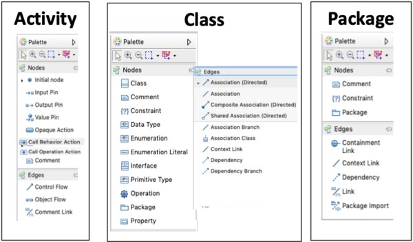
Comparing Papyrus and Papyrus UMLLight Diagram Support
| Papyrus vs. Papyrus UMLLight Diagrams | |
|---|---|
| Papyrus | 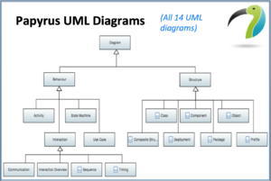 |
| Papyrus UMLLight | |
(highlighted diagrams are supported)
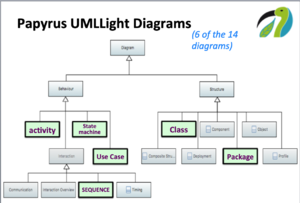
In addition, the content of each Papyrus UMLLight diagram’s palette has been modified.
Installing Papyrus UMLLight

The list of downloads for different operating environments will be displayed: * Papyrus UML Light 0.0.1 RC2* for Windows 64bit * Papyrus UML Light 0.0.1 RC2* for Linux 64bit * Papyrus UML Light 0.0.1 RC2* for MacOS X 64bit

4. To download the archive, click on the link for your development environment.
5. Extract the executable from the downloaded archive into the proper location for applications on your operating system.
Tip: On MacOS and some Linux, you may need to use “gunzip” followed by “tar xvf” to successfully extract the archive.
6. You are now ready to start using Papyrus UML Light!
Starting Papyrus UMLLight
1. Double-click on the Papyrus UMLLight application you installed in the previous step.
2. A dialog is shown asking you to select a workspace.
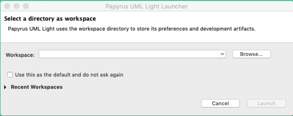
About Workspaces
Selecting a workspace
1. ☐ Click on browse to select a folder that will hold your work.
2. ☐ Click “Launch” to start Papyrus UMLLight
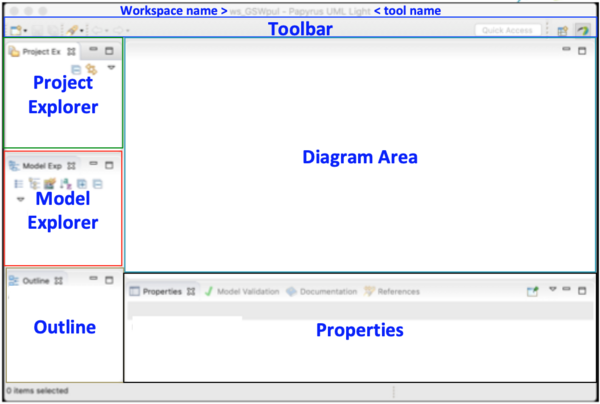
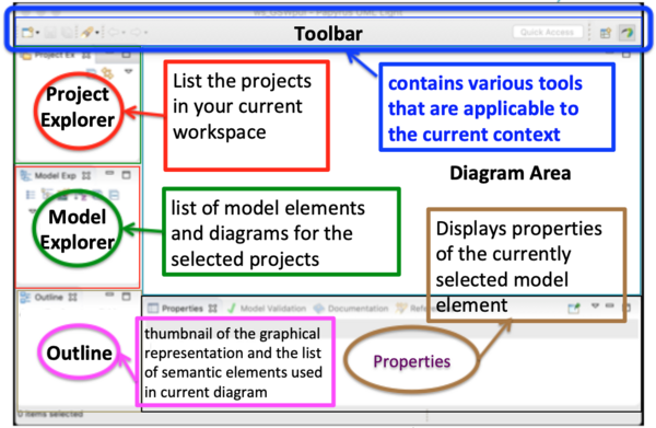
3. ☐ The Papyrus UMLLight development environment is displayed, The first image shows the six main areas and the second, what you their use and content.
Palettes
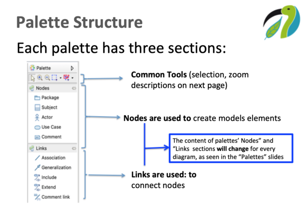
Palette Structure
Customized Palettes
In addition to the common tools, every Papyrus UMLLight diagram has a customized palette” containing the model elements that can be used with that diagram. You can think of it as your modeling “toolbox”. Each Papyrus UMLLight diagram’s palette is customized to meet the simplification goals of Papyrus UMLLight.
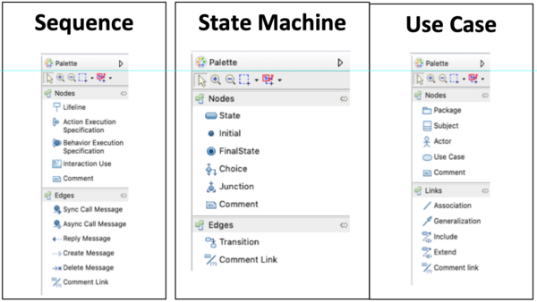
Diagram Palettes
Views of all the Papyrus UMLLight Palettes (in alphabetical order)
Before we go any further, let’s have a look at the tutorial project so we can start implementing it!
Online Shopping System (OSS) Project Overview
The Online Shopping System (OSS) is a web-based system that allows customers to
- browse and search for products available in the catalogue and view their information;
- Add/remove products to/from a virtual shopping cart;
- View the content of the chopping cart;
- Purchase shopping cart products using a Credit or an online payment service (e.g., PayPal)
- Have the purchased items delivered.
Given these descriptions, we can deduce the following preliminary list of actors and use cases:
| Actors | Customer | Customer Database | Product Manager | Product Database | Payment Service |
|---|---|---|---|---|---|
| Use Cases | Login | Approve login | Add product | Store product information | Processes payment request |
| Find (browse/search for) Product | Remove product | Store art information | provide payment status | ||
| Add product to cart | Update product (e.g., pricing) | ||||
| View Cart | List existing products (inventory) | ||||
| Checkout |
More use cases and actors will naturally be discovered as we go through the creation of the model that will describes the OSS system.
Use Case Modeling
Therefore it is about about users, their needs, and how they interact with the system being built, as well as how the OSS system interacts with other systems.
Before We start, let’s understand the main concepts of use case modeling.
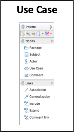
Basic Use Case Diagram Concepts
| Basic Use Case Diagram Concepts | |
|---|---|
| Nodes | |
| Subject | The subject represents the system under consideration («OSS» in our case) to which a set of use cases applies. As such, it also represents the boundary between our system and it’s interactions with the «outside world.» What is inside the subject constitutes the functionality of the system and what lies outside represent elements that interact with OSS, by providing input or services. |
| Actor | An Actor models a role played by an entity that interacts with the subject (e.g., by exchanging signals and data) but which is external to the subject, e.g., users accessing OSS or providing a service, e.g., an bank’s payment service). As you can see, both people and external systems actors can be actors. |
| Use Case | A use case is the specification of a set of actions performed by the system, which yields observable results of value to one or more actors or other stakeholders of the system. < Adapted from UML Superstructure Specification, v2.4.1>.Use cases are typically described as a sequence of steps. This sequence can be illustrated by using a sequence diagram to model the sequence of steps and can also be expressed textually (an example is provided a the end of this tutorial for those interested). |
| Comment | Textual annotation attached to a set of elements. |
| Edges | |
| Association | The association relationship is used to link actors to the use cases affected by them.* The association relationship, being bidirectional, does not indicate directionality and can therefore be draw in either direction. |
| Generalization | The “Generalization” relationship is used to specify inheritance/generalization relationships between use cases or actors.* The relationship is drawn from the specialized entity to the general entity. |
| Include | Simplify a use case by decomposing it into smaller use cases with the goal of increasing modularity and reusability.* The include relationship is drawn from the including element to the included element.* A use case «A» included in use case»B indicates that «B» requires «A» to accomplish its goals. |
| Extend | The extend relationship is drawn from the extender element to the extended element.* a use case «C» Extends use case «D» indicates that use case «C» is an optional part of use case D. |
| Comment Link | The comment link is used to connect a comment to the element to which the comment applies. |
Creating the OSS Use Case model
The time has come for you to start modeling!
Create and initialize the OSS Project
First, you need to create a project For your OSS model:
1. ☐ From the Papyrus UMLLight main menu, select “File >New UML Light Project” to create the OSS project.
2. ☐ In the ‘«New UML Light Model Project» resulting dialog, set the project name to «OSS»
3. ☐ Leave the location as is (default).
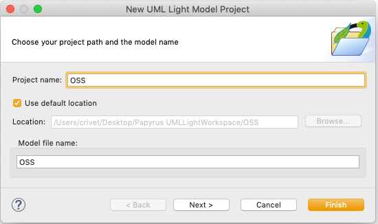
4. ☐ Click on [Next] to display the»initialization information» dialog.
5. ☐ check the box left of the «Light Use Case Diagram.
This will create an empty use case diagram as part of the project creation.
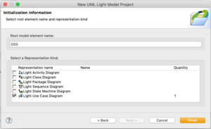

6. ☐ Click on «Finish.»
Your project has been created and it is displayed in the workspace:
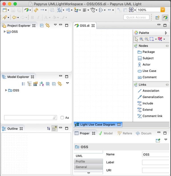
What was created
Before we move on, let’s look at what was created.
The project Explorer
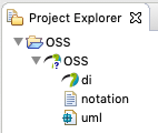
In the project explorer, There is now an entry titled «OSS» That is the project you just created as stored on disk. If you expand it, it will look like this:
The Model Explorer
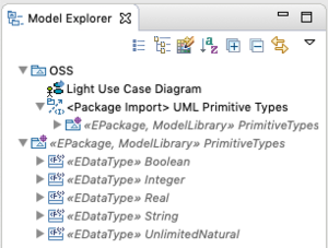
The model elements under OSS have been created as part of the initial model creation.You can see that a «Light Use Case Diagram has been created as expected. In addition, Papyrus UMLLight also automatically includes a library of UML primitives that define data types. Those will be useful later in the tutorial.
The workspace is now ready for the creation of the use case model
![]()
Populate the OSS Use Case Diagram
Adding the Subject

- ☐ In the palette, click on the Subject
 and then click in the middle of the diagram to create the subject.
 - ☐ Note that the subject object is also visible in both the model explorer and in the Properties view. Each of these views (diagram, model explorer, and property) provide a representation of the same, single model element in each of these particular contexts. Each “view” provides a set of information about that model element.
- ☐ Rename the subject to «OSS» by clicking on the Subject to display its properties view and, from the the properties view, change the value of the name property to «OSS». You will notice that the name also changes in the diagram and Model Explorer.
- ☐ Now Click and drag an actor from the palette to a location at the left of the subject. Drag and drop is another way to place elements on a diagram.
 and then click in the middle of the diagram to create the subject.
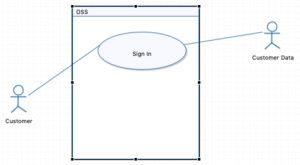
Complete the use case diagram
Now that you know how to add use case diagram elements, Use the information from the Actors and Use Cases table to complete the use case diagram.
When done, Your use case diagram should be similar to: 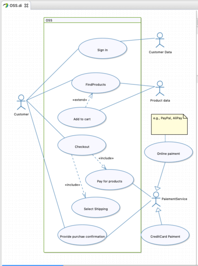
Documentation View
The documentation view provides a mechanism to add documentation to a model element. Although this is useful in many areas of modeling, it is very helpful when doing use case analysis at the beginning of the project where you can use this capability to add textual information to better textually describe the actors and to provide a textual description of the use cases. To show the documentation view and edit its content, right-click on a model element on a diagram and select “Show Documentation view” and the Properties view will display the documentation view.
Adding documentation to a use case
- Right-click on the «FindProducts» use case and select «Show Documentation View» command
- In the «Find Products» input, add your documentation for that use case.
Example of the documentation view.
This is an example of a use case’s requirements documented with using user stories. 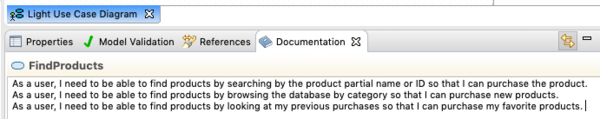
Use Case Analysis
What do we mean by «Use Case Analysis»?
Using Class diagrams
Role of Class Diagrams
Class diagrams are used to describe the structure of the software system’s elements. In fact, you have already seen a class diagram — the images of the supported diagrams in Papyrus and Papyrus UMLLight are examples of lass diagrams! We use the class diagrams to represent the structure of elements we define such as the the shopping cart, and the database actors, and the information for all the products.
Creating a class diagram for the shopping Cart
1. ☐ Right-click on the OSS Model in the model explorer and add a «New light class diagram»
2. ☐ Name the diagram «Shopping Cart».
3. ☐ Add two side-by-side classes to the diagram and name them «ShoppingCart» and «Product».
4. ☐ Draw a directed association from the Shopping Cart class to the Product Class
7. ☐ We already know, from the «Actors and Use Cases table», that the shopping cart can add and remove a product to the cart, so let’s add these capabilities as operations on the Shopping Cart
8 . ☐ Click on the Shopping Cart and let your cursor over on the Shopping Cart
10. ☐ A little toolbox will appear above the Shopping cart — click on the gear icon, which represents operations..
11. ☐ You will see an operation added to the bottom «(OPerations)» compartment of the class. Rename the operation «Add Product».
12. Add one more operation named: «Remove Product»
13. ☐ To add the property, Click on the property in the the palette and then click on the Shopping Cart’s upper compartment.
14. Name this property «CardId». This will allow the system to keep track of the cart.
15. ☐ Using the properties
16. ☐ Both classes require a unique identifier so that multiple users can shop simultaneously — let start with the Shopping Cart: Click on an empty part of the shopping cart and when the pop-up appears, click on the box to create a new property. Click on the property and name it «ShoppingCartID.
17. ☐ left-Click on the property just created in the ShoppingCart class and select «Show Properties View», The property’s properties are now shown.
18. ☐ Rename the new property to «ShoppingCartID».
19. ☐ «Click on the [. ] icon to the right of the type field to display the type library. Expand the «ModelLibrary Primitive Types by clicking on the triangle on the left and select string to hold the ID. Click on OK to close the dialog.
20. Go through the same process to add the ID to the Product, naming the property «ProductID».
21. ☐ The product cart also has to be associated with the customer — so you need to create the class for the customer and link it to the shopping cart.
22. ☐ Add a class to the diagram and name it «Customer».
24. ☐ Add a string field named “Customer Name» to the customer class
25. ☐ Similarly to what you did for the Shopping Cart and Product, add a customer ID attribute to the customer class.
Using activity and Sequence Diagrams
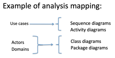
- At the use case analysis level, Activity and Sequence diagrams are used to provide the bridge between the use case and the system design models.
- Sequence diagrams and activity diagrams provide two complementary graphical views of use cases
* Activity diagrams focus on the description of the use cases as a workflow or process * Sequence diagrams focus on the order of the message with regards to time.
Activity Diagrams
Role of Activity diagrams
Basic Activity Diagram Concepts
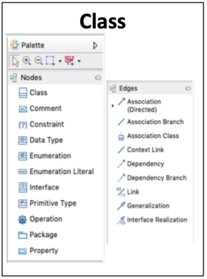
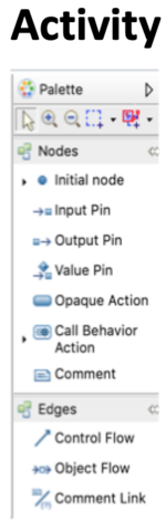
Refer to the activity diagram palette for the icons associated with the following model elements.
| Basic Activity Diagram Concepts | |
|---|---|
| Nodes | |
| Name | Description |
| Initial Node | Acts as a starting point for executing an Activity |
| Input Pin | Holds input values to be consumed by an Action |
| Output pin | Holds output values produced by an Action |
| Value Pin | Provides a value by evaluating a ValueSpecification |
| Opaque Action | Action not specified within UML, e.g., using normal language. |
| Call Behavior Action | Directly invokes a Behavior |
| Edges | |
| Name | Description |
| Control Flow | Used to control the execution of ExecutableNodes |
| ObjectFlow | ActivityEdge that can carry,object,tokens that may hold values |
Creating an activity diagram for a customer purchase
In this exercise, you will create an activity diagram for a customer checking out.
1. ☐ Add an an activity diagram named «customer Checkout» to the model. and rename the activity «Customer checkout.»
2. ☐ Add an «initial node» to the top left of the diagram. This is where the activity Starts.
3. ☐ Add an opaque Action below and to the right of the initial node and name it » customer «to checks out.».
4. ☐ Add a decision node to the right of the opaque action
5. ☐ Draw a control flow from the opaque action to the decision node and name it : «customer signed in?»
6. ☐ Add an opaque action named «Customer Login» to the right of the decision node.
7. ☐ Add a control flow named «false» from the decision node to the Customer Login opaque behavior.
8. ☐ Add a decision node below the customer login behavior and draw a control Flow named «Login success» from customer Login to it.
9. ☐ Add an Activity Final node to the right of the last decision node and draw a control flow named «false» to it.
10. ☐ Add a merge node to the left of the «login success» decision node and below the «customer signed in» decision node and draw control flows named «true» from the two decision nodes to the merge node.
11. ☐ Add an opaque action named «OSS retrieves customer information from customer database» below the merge node and draw a control flow from the merge node to this opaque action.
12. ☐ Add an opaque action below the previous one and draw a control flow from the previous opaque action to the new one.
13. ☐ Customer confirms the existing address.
14. ☐ In the same way, add an opaque action below the previous one named «OSS asked customer to select shipping option»
15. ☐ similarly, add opaque Actions and control flows for the following opaque actions:
OSS prepares the invoice OSS displays the final invoice OSS processes payment OSS Displays final transaction receipt and sends a copy to the customer’s email address OSS returns to the welcome page
16. ☐ Add an activity final node and draw a control flow from the previous opaque action to the final node.
Sequence Diagrams
Role of sequence diagrams
- At the use case analysis level, the role of sequence diagrams is to describe the use cases as a sequence of interactions between the system and the different actors
* Sequence diagrams also include the specification of the main internal actions executed by the system in the execution of the use cases.
- While UML provides a rich set of concepts/notations for sequence diagrams the subset provided by Papyrus UMLLight is more than adequate for our purpose.
Basic Sequence Diagram Concepts
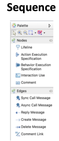
Refer to the sequence diagram palette for the icons associated with the following model elements.
| Basic Sequence Diagram Concepts | |
|---|---|
| Nodes | |
| Name | Description |
| LifeLine | A Lifeline represents a single individual participant (e.g., instance of an actor) in the sequence diagram. |
| Action Execution Specification | The specification of a single executable unit of functionality. |
| Behavior Execution Specification | Whereas the Action was a single unit of functionality, behaviour is a specification of events that may occur dynamically over time (e.g., an ordered set of actions, an opaque behavior, or an activity.) |
| Interaction Use | Allows the reuse of an interaction from within another one. Tip: Often seen as an «include» relationship in the use case diagram. |
| Edges | |
| Name | Description |
| Sync Call Message | A message generated by a synchronous call to an operation — a reply is automatically provided |
| Async Call Message | A message generated by an asynchronous call to an operation. A reply message is not provide but is expected. |
| Reply message | Used to reply to an Async Call Message |
| Create message | Create a new lifeline |
| Delete message | Delete (end) a an existing lifeline |
Creating a sequence diagram for a Customer Login
In this exercise, you will create a sequence diagram that shows the process for the customer to logging into the OSS.
1. ☐ Add a LightSequenceDiagram to the OSS model.
2. ☐ Rename the diagram and the generated interaction to “CustomerLogin»
3. ☐ Create a “Customer» timeline By dragging the «Customer» class from the model explorer and dropping it on the left side of the sequence diagram.
4. ☐ Use the timeline tool to and add a timeline to the right of the Customer timeline — be sure to leave some space to the right.
5. ☐ Find the OSS Subject in the model explorer and drop it on the new, just created timeline so that the timeline is now a representation of the OSS functionality
6. ☐ Draw an ‘Async Call Message’’’ from the customer timeline to the OSS timeline and rename the message Provide user identifier. This is the customer providing Their user ID.
7. ☐ Drag and drop an action execution specification specification on the OSS timeline, below «provide user identifier and name it «CheckID». This Action will let the OSS system determine if the identifier is valid.
Draw an Reply Message from the bottom of the CheckID action execution to the Customer timeline and name it «ValidID, letting the customer know that the ID is valid.
8. ☐ Draw another Async Call Message below the previous one and call it Provide password from the customer
timeline to the OSS timeline and rename the message ‘Provide password. This is the customer providing their password.
9. ☐ Draw an ‘Async Call Message’’’ from the customer timeline to the OSS timeline and rename the message Password user identifier. This is the customer providing Their user ID.
10. ☐ As was done for the user identifier, add and Action Execution that will return that access is approved.
11. ☐ Add another lifeline on the right and name it Shopping Session.
12 ☐ Draw a Create message from the OSS timeline to the Shopping Session timeline.
11. ☐ Below the last message on the customer timeline, draw an Async cCall message message from the the customer to the OSS and name it Logout
12. ☐ Below the last message on the customer timeline, draw an Async message from the the customer to the OSS and name it Logout
13. ☐ Finaly, draw a delete message from the OSS to the Shopping session timeline.
State Machine Diagrams
Role of State Machine Diagrams
- The role of State Machine Diagrams is to describe the various states of the system or its components and the possible transition between these states.
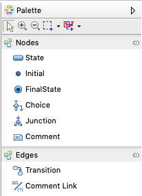
Basic State Machine Diagram Concepts
Refer to the State Machine diagram palette for the icons associated with the following model elements.
| Basic State Machine Diagram Concepts | |
|---|---|
| Nodes | |
| State | Formally: Situation during which an invariant condition holds. In effect, it is waiting for a signal |
| Initial | Where the state machine starts. It will stay in that state until a message is received. |
| FinalState | Indicate the completion of the state machine |
| Choice | Dynamic conditional branching to select a continuing path |
| Junction | Connect multiple Transitions into compound paths between |
| Comment | Textual annotation attached to a set of elements. |
| Edges | |
| Transition | Represents a path from a single source element to another single element |
| Comment Link | Represents a link from a comment to the element being commented upon. |
Modeling scenario — OSS purchase delivery Statemachine
To demonstrate the creation of a state machine, we will be looking at the process of delivering a customer’s the purchased goods.
| Modeling scenario — OSS purchase delivery Statemachine | |
|---|---|
| Event | Resulting State |
| 1. Customer is shopping (browsing/searching for products) | Shopping |
| 2. Customer adds a product to cart — OSS puts a time-limited hold on the selected product and quantity | Shopping — Cart Cart stays in shopping state as products are added |
| 3. Customer checks out and pays | Checkout |
| 4. OSS receives Payment approval | Ready to package |
| 5. Customer confirms shipping address | Preparing shipment |
| 6. Customer purchases packaged | Ready to Ship |
| 7. Package is taken over by delivery company | In Transit |
| 8. Customer signs for package | Purchases delivered |
Now that we have our scenario, let’s create its state machine.
1. ☐ Add a Light State machine diagram to the model and name it OSS Purchase and Delivery.
2. ☐ Add an initial point in the top left corner of the diagram. This will be the starting point of your state machine execution.
3. ☐ Add a state to the right and a bit lower than the initial point and name it Shopping.
4. ☐ Draw a connector from the initial point to the Shopping state you just added. This indicates that when the state machine is started it will start in the Shopping state.
5. ☐ Add a transition that both starts and ends on the Shopping state and name it AddProduct. This kind of transition is called a self-transition and it is useful if you need to process a series of transition that do not change the state of the system.
6. ☐ Add a state to the right of the Shopping State and name it Checkout. Draw a transition from the Shopping state to this new state and name it Customer checks out and pays. This indicates that the customer has finished shopping.
7. ☐ Add a state to the right of the Checkout state, name it Prepare shipment, and add a transition from Checkout to this new state named Payment approved.
8. ☐ Add a new state named Ready to Ship below the Prepare statement shape and draw a transition from the Prepare Shipment state to this new one named Shipment packaged.
9. ☐ Add a state named InTransit’ to the left of Ready to Ship’ and then draw a transition named Delivery company Pickup from Ready to Ship’ to this new state.
10. ☐ At a self-transition on the left side of the InTransit state named Transit updates This will be used to send delivery information and updates to the customer.
11. ☐ Finally, add a Final state named Signature receivedat the bottom of the InTransit state.
Congratulation, you have created a state machine!
Adding Structure to models
model, typically to manage groups of similar or related model elements.
- Examples of package usage:
* Separating common elements into logical groups * Separating parts of the model using packages also enables reams to work in parallel on different packages (although this is out of the scope of this tutorial). :: An example of the use of packages can be seen in the implementation of a layered model architectures (e.g., with presentation, business, persistence layers). * The use of packages also facilitate the visualization of a coarse level of traceability across the development lifecycle.
Package Diagram
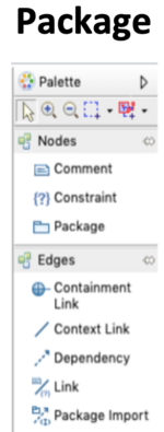
Creating the package diagram
1. ☐ Click on the model in the model explorer.
2. ☐ From the main toolbar, Select Papyrus > “New Diagram > Light Package Diagram.
3. ☐ Name the diagram “Packaging exercise” and click “OK”
4. ☐ The use case diagram has been replaced by the new diagram Package in the model editor, but is still available as a tab if you need to get back to it. As you create new diagrams, they will be listed there until you close them.
5. ☐ As well, the palette has changed to display the tools for package diagrams.
6. ☐ Using the palette, add a package at the top left of the diagram and name it “Use Case Model
7. ☐ Add another package below and slightly to the right of the Use Case Model package and name it “Design Model”.
8. Draw a dependency from the left side of the Design Model package to the bottom of the Use Case Model
9. ☐ To make the dependency look better, click in the middle of the dependency and drag left and down to make a nice elbow connector.
This dependency indicates that the “Design Model” is dependent on one or more element found in the “Use Case Model” package.
10. ☐ In the Model Explorer, you can now the use case model elements into their UseCase model package and do the same for the design models elements into the Design package.
11. ☐ Your diagram and model should look similar to:
Источник


