How car electrical systems work
The Video Course teaches you everything about modern cars.
The electrical system of a car is a closed circuit with an independent power source the battery . It operates on a small fraction of the power of a household circuit.
Current flows along a single cable from the battery to the component being powered, and back to the battery through the car’s metal body. The body is connected to the earth terminal of the battery by a thick cable.
This type of circuit is called an earth-return system any part of it connected to the car body is said to be earthed.
The strength of the current is measured in amperes (amps); the pressure that drives it round the circuit is called voltage ( volts ). Modern cars have a 12 volt battery. Its capacity is measured in amp/hours. A 56 amp/hour battery should be able to deliver a current of 1 amp for 56 hours, or 2 amps for 28 hours.
If the battery voltage drops, less current flows, and eventually there is not enough to make the components work.
Current, voltage and resistance
The extent to which a wire resists the flow of current is called resistance , and is measured in ohms .
Thin wires conduct less easily than thick ones, because there is less room for the electrons to travel through.
The energy needed to push current through a resistance is transformed into heat. This can be useful, for example in the very thin filament of a light bulb, which glows white hot.
However, a component with a high current consumption must not be connected using wires which are too thin, or the wires will overheat, blow a fuse , or burn out.
All the electrical units of measurement are interrelated: a pressure of 1 volt causes a current of 1 amp to flow through a resistance of 1 ohm. Volts divided by ohms equal amps. For example, a light bulb with a resistance of 3 ohms, in a 12 volt system, consumes 4 amps.
This means it must be connected using wires thick enough to carry 4 amps comfortably.
Often the power consumption of a component will be stated in watts , which are found by multiplying amps and volts. The lamp in the example consumes 48 watts.
Positive and negative polarity
Electricity flows from a battery in one direction only, and some components work only if the flow through them is in the correct direction.
This acceptance of a one-way flow is called polarity . On most cars the negative () battery terminal is earthed and the positive (+) one feeds the electrical system.
This is called a negative earth system, and when buying an electrical accessory a radio, for example check that it is of a type suitable for your car’s system. Fitting a radio with the incorrect polarity will damage the set, but most car radios have an external switch for setting the polarity to suit that of the car. Switch to the correct setting before fitting.
Short circuits and fuses
If the wrong-sized wire is used, or if a wire becomes broken or disconnected, this can cause an accidental short circuit which bypasses the resistance of the component. The current in the wire may become dangerously high and melt the wire or cause a fire.
To guard against this, ancillary circuits have fuses.
The most common type of fuse is a short length of thin wire enclosed in a heatproof casing often glass.
The size of the fuse wire is the thinnest that can carry the normal current of the circuit without overheating, and it is rated in amps.
The sudden surge of high current in a short circuit makes the fuse wire melt, or ‘blow’, breaking the circuit.
When this happens, see if there is a short circuit or a disconnection, then install a new fuse of the correct amperage rating (See Checking and replacing fuses ).
There are many fuses, each protecting a small group of components, so that one blown fuse does not shut down the whole system. Many of the fuses are grouped together in a fuse box, but there may also be line fuses in the wiring.
Series and parallel circuits
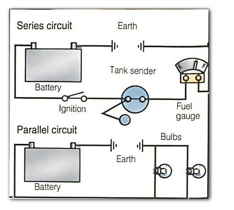
A circuit usually includes more than one component, such as bulbs in the lighting circuits. It matters whether they are connected in series one after the other or in parallel side by side.
A headlamp bulb, for example, is designed to have a degree of resistance so that it consumes a certain current to glow normally.
But there are at least two headlamps in the circuit. If they were connected in series, electric current would have to go through one headlamp to get to the other.
The current would encounter the resistance twice, and the double resistance would halve the current, so that the bulbs would glow only feebly.
Connecting the bulbs in parallel means that electricity goes through each bulb only once.
Some components must be connected in series. For example, the sender in the fuel tank varies its resistance according to the amount of fuel in the tank, and ‘sends’ a small electrical current to the fuel gauge.
The two components are connected in series so that the varying resistance in the sender will affect the position of the needle on the gauge.
Ancillary circuits
The starter motor has its own heavy cable, direct from the battery. The ignition circuit furnishes the high-tension impulses to the sparkplugs; and the charging system includes the generator , which recharges the battery. All the other circuits are called ancillary (subsidiary) circuits.
Most are wired through the ignition switch , so that they work only when the ignition is switched on.
This prevents you accidentally leaving something switched on which might cause the battery to go flat.
The side and tail lights, however, which you may need to leave on when the car is parked, are always wired independently of the ignition switch.
When fitting extra accessories, such as a rear window heater which consumes a heavy current, always wire it through the ignition switch.
Some ancillary components can be operated without the ignition turned on by turning the switch to the ‘auxiliary’ position. A radio is usually wired through this switch, so that it can be played with the engine off.
Wires and printed circuits
Wire and cable sizes are classified by the maximum amperage that they can carry safely.
A complex network of wires runs through the car. To avoid confusion, each wire is colour coded (but only within the car: there is no national or international system of colour-coding).
Most car handbooks and service manuals include a wiring diagram which can be difficult to follow.
The colour-coding, however, is a useful guide to tracing wiring.
Where wires run side-by-side they are bound together in a bundle, in a plastic or fabric sheath, to keep them tidy and less difficult to fit .
This bundle of wires stretches over the length of the car, with single wires or small groups of wires emerging where necessary, and is called the wiring loom.
Modern cars often need room for many wires in confined spaces. Some manufacturers now use printed circuits instead of bundles of wires, particularly at the rear of the instrument panel.
Printed circuits are plastic sheets on which copper tracks have been ‘printed’. Components are plugged directly into the tracks.
How Electrical Systems Work
A car’s electrical system is not that complicated
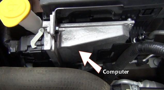
Every car’s electrical system is composed of a wiring harness that connects various computer, controllers, lights, actuators, motors and switches. This electrical system is intergraded throughout the car to communicate with each part using a central computer which runs the engine or main electric motor. The battery is responsible for supplying power to the car while the engine is not running but in electric cars the battery does all of the work while powering the motor. High amperage circuits are designed with larger components to handle the load without failing. Common maintenance includes inspecting electrical connectors that are visible including the battery cables.
What Goes Wrong?
The most common problems with electrical systems are a short or open circuit. A short circuit is what happens when a wire has rubbed through to ground causing a fuse to blow. An open circuit is what happens when a connection stops working because of a broken wire or a bad conductivity. Low battery voltage can cause strange problems to the electrical components of the car due to insufficient operating voltage. Because of the construction of wiring connectors they can sometimes create high resistance which causes heat making the connector have an open circuit. When performing wiring repairs a wiring schematic is sometimes necessary to trace wires or locate a component.
Let’s Get Started
The electrical system of any vehicle performs the same function. To deliver and monitor electrical power to various devices and sensors while under control of the computer system or a passenger inside the car.
Wiring harness are groups of wires which are taped up in plastic tubes and routed around the car and throughout the engine compartment.

A wiring harness has many connectors that can serve as an extension to the main harness which allows routing to devices which are located beyond the reach of the main harness.
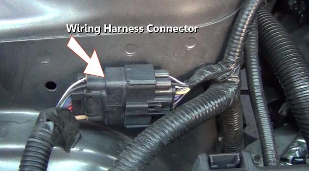
Connectors are disconnected by depressing a small tab on the side of the connector. Once apart the male side of the connector is designed with terminals that protrude outward which fit into sockets on the female side. Electrical or wire connectors can vary from a single terminal to many terminal depending on the application. Wire and connectors vary in size due to different amperage loads for each circuit.

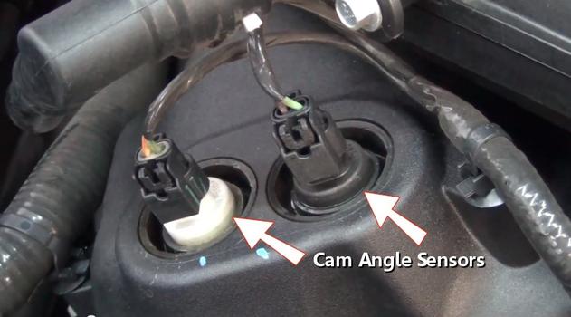
A device connector is used to connect to a particular item in the electrical system such as ignition coils which are shown in the image below. A safety is used to securely attach the connector to a device which adds an extra layer of protection from accidental disconnection. This safety clip must be removed before the connector can be released.

An electronic throttle control actuator is responsible for metering air flow into the engine which controls engine speed. A throttle control sensor located near the foot pedal supplies feedback data to the computer which activates the actuator. The throttle control system is integrated into the ABS, cruise control and traction control systems. In older vehicles throttle action was performed by a manually controlled throttle cable which is actuated by the driver’s right foot.

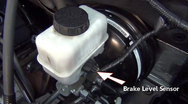
The anti-lock brake system controller is an electronic system that helps prevent the wheels from skidding in panic stop and is integrated into the traction control system.

Sensors provide feedback data to the main computer which in turn will illuminate the brake warning light when fluid levels have decreased.
Sensors such as the camshaft angle sensors use thin metal windings which break a magnetic field as the shaft rotates causing a pulse that is sensed by the computer.
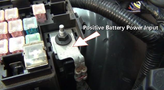
A power distribution center is used to route positive battery power throughout the vehicle using relays and fuses. This center is powered directly off of the positive post of the battery using a positive battery cable.

Inside the PDC are many fuses and relays which protect and control the many electrical circuits such as fuel pump and fuel injection systems. Fuses are used to safeguard electrical circuits and are designed to pop stopping the voltage flow in the event of a power overload or short circuit protecting the circuit wire from burning.
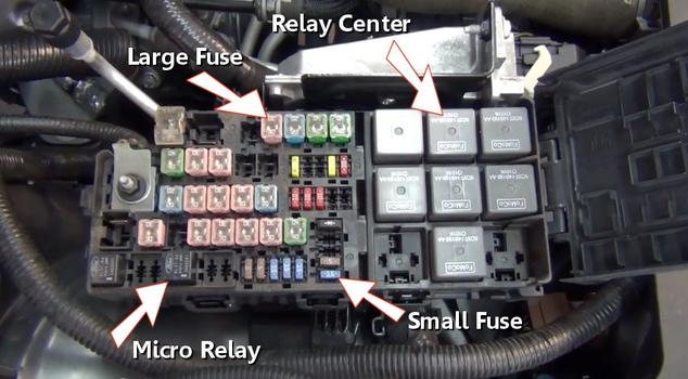
A set of control relays act as the main switching center of the electrical power. These relay’s act as electronic switches that are controlled by the computer or by a manual switch. Once engaged the relay connects a circuit which activates a particular device.

A set of large amperage fuses protect high amperage circuits such as the cooling fan, starter solenoid and headlights. A observation window is provided to inspect the fuse’s condition.

Medium duty fuses are used to protect average amperage circuits such as power windows and seat heaters. These fuses also provide an observation window which is needed for inspection.

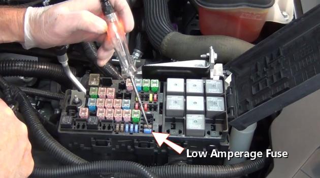
Finally low amperage fuses are used to protect smaller amperage circuits such as tail lights and interior lighting. These fuses are easily checked using a test light.
The battery supplies both positive and ground circuits which complete the electron cycle. The positive side of the system circuit starts at the PDC provided by the battery.
The automotive battery is designed as an electrical storage device and is responsible for delivering electrical power when the engine is not in operation. All batteries possess a negative (ground) and positive (power) attribute of an electrical power system. These connections should be free of corrosion and rust as contaminates hinder the proper operation of electrical circuits. A periodic inspection and test of the battery is necessary to avoid roadside failures. Battery terminals can develop corrosion due to the flow of ions. Terminal and cable cleaning is necessary to remedy this condition.
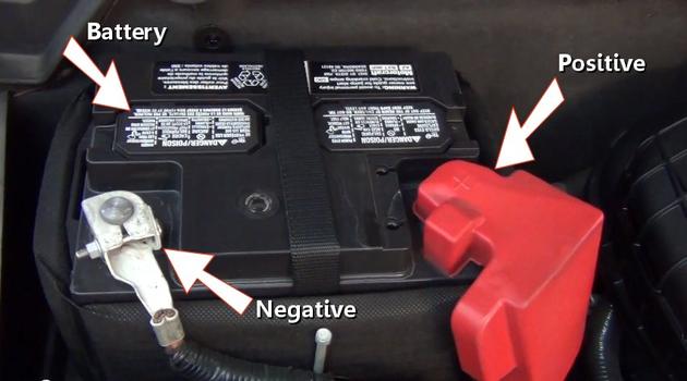
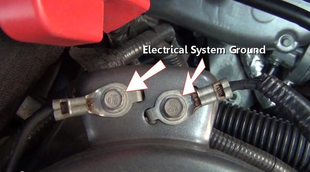
The negative side of the battery is connected to the body, frame and engine block of the vehicle. These metal parts acts as a conductive connector for positive battery power completing the electrical circuit.
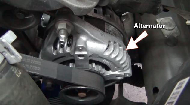
Thealternator is powered by the engine connected by a serpentine belt. This unit creates electrical power by utilizing a magnetized armature and outer copper windings which are connected to the battery using brushes. While in operation (engine running) this unit supplies electrical power for the vehicle while charging the battery at the same time.
The engine starter motor is designed to turn the engine over when the ignition switch is activated. This device pulls the most amperage of all components encompassed within a vehicle except in hybrid and electric vehicles.

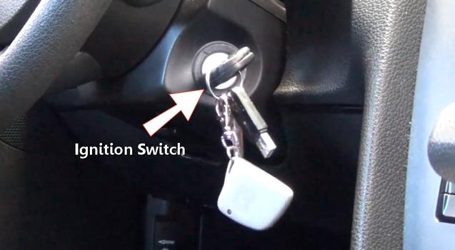
The ignition switch is what controls the electrical system within a locking mechanism that utilizes a key for security. These keys possess a frequency chip as an added theft deterrent.
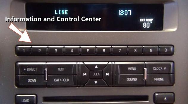
An information control center is used for interior controls such cell phone, GPS and audio system adjustments.
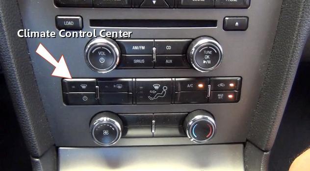
Electronic climate controls enable the driver and passenger to adjust temperature in a particular section of the vehicle such as engaging the air conditioner or heater.
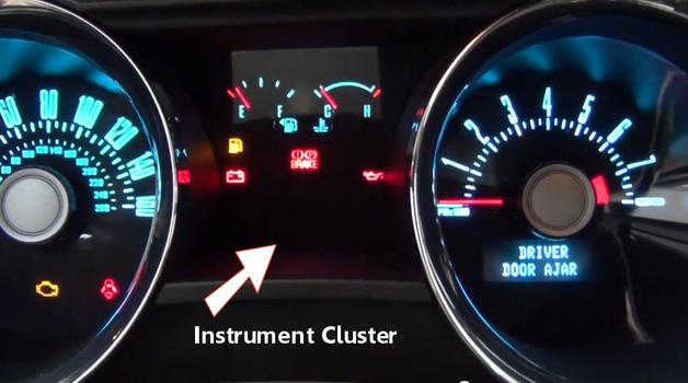
The car’s instrument cluster is used to monitor engine and others system by using gauges and warning lights.
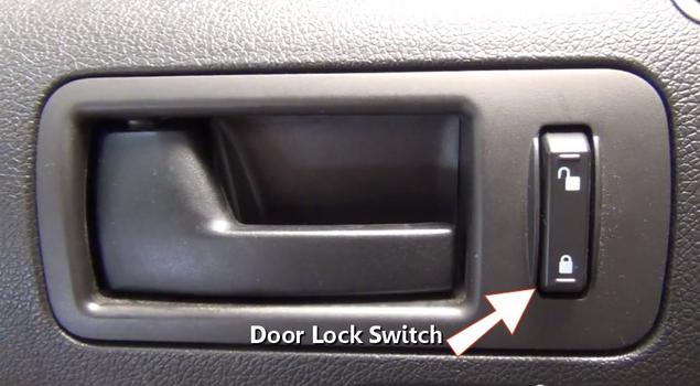
There and many switches that are used to control various items such as door locks and headlights. These switches are user controlled and can be overridden by the main computer.
Interior lighting controls are automatically illuminated by the BCM computer. They can also be controlled by the driver or passenger.
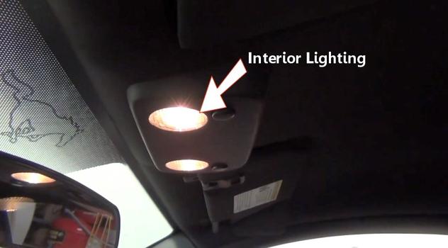
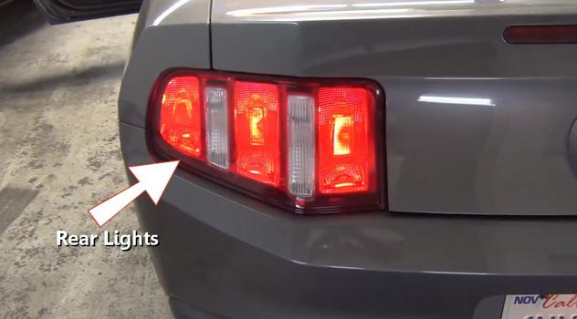
The lighting system is used to illuminate the vehicle for safety and for convenience. The rear lights include, tail, brake, reverse and license plate bulbs.
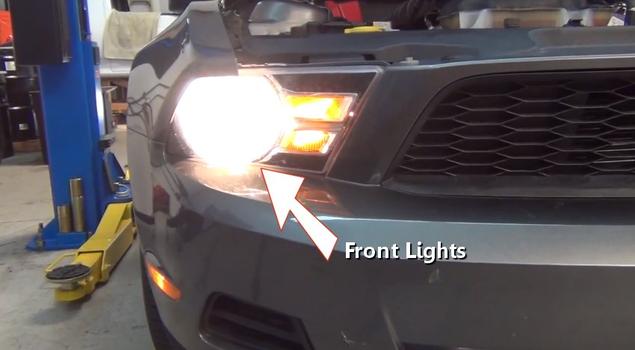
The front of a vehicle is designed with headlights, front running, side marker and blinker bulbs.
We hope you enjoyed this guide and video. We are creating a full set of car repair guides. Please subscribe to our 2CarPros YouTube channel and check back often for new videos which are uploaded almost every day.


