- Esptool
- Download Esptool If you do not have an installed copy of Python 2.x or 3.x download and install it from https://www.python.org/. Download Esptool Source code from https://github.com/espressif/esptool/releases to a known folder. Install Esptool Go to the known folder and install Esptool with command python setup.py install . Packages for Esptool are maintained for Debian and Ubuntu and can be installed with sudo apt install esptool . Download Tasmota Download the latest Tasmota release firmware file tasmota.bin to a known folder. Upload Tasmota Put device in firmware upload mode When performing a firmware upload do not connect the device to AC but use the power supply provided by your (FTDI type) serial interface. Put the device in firmware upload mode by grounding pin GPIO00 while applying power. Grounding pin GPIO00 can often be achieved by pressing button 1 on the Sonoff device or using a wire between GPIO00 and Gnd if the button is not available. Deviations may apply. Connect the serial interface of your PC to the device while GPIO00 to Gnd. Esptool uses the serial interface to communicate with your device. On Windows these interfaces are named COM1, COM2 etc. On Linux these interfaces are called /dev/ttyUSB0, /dev/ttyUSB1 etc. Before using Esptool make sure you know to which serial interface name your device is connected to. In the following commands I use COM5 as an example. Optional: Backup firmware Ensure the device is in firmware upload mode. Backup the current firmware with the following command: Erase firmware Ensure the device is in firmware upload mode. Erase the complete flash memory holding the firmware with the following command: NOTE2: It only takes a few seconds to erase 1M of flash. Upload firmware Ensure the device is in firmware upload mode. Load the downloaded Tasmota firmware file tasmota.bin with the following command: NOTE2: For a proper device initialization after first firmware upload power down and power up the device. ESPTOOL Executable (Windows & Linux) The executable version of esptool is maintained by Ivan Grokhotkov and releases are kept at https://github.com/igrr/esptool-ck/releases Download and Install For the purpose of simplicity only the Windows version will be explained here, but the command and parameters are the same for Windows, Linux and MAC/OSX. Download the latest release from https://github.com/igrr/esptool-ck/releases and extract the compressed file to a known location. Download Tasmota Download the latest Tasmota release firmware file tasmota.bin to a known folder (The same folder as where you have the esptool executable will work well for this process to be simpler) If you want features from the current development codebase which has not been included in the last release please download this tasmota.bin to a known folder (The same folder as where you have the esptool executable will work well for this process to be simpler) The information posted further up in this Wiki for placing the device into bootload / firmware upgrade mode may be followed as this process does not change irrespective whether you use the Python or executable version of esptool. Once the device is in firmware upload mode the following commands are recommended for completion of the firmware flashing. Erase the flash completely with the following command (substituting the COM port for the one which was used on your computer) esptool -cp COM3 -cb 115200 -ce -v Once the erase is complete, reset your device back into programming mode and then upload the firmware using the following command Источник FlashingВ¶ The programming procedures for flashing an ESP82xx and ESP32 via the serial port differ slightly. In general the steps are the same to enter flashing mode on both types ESP boards: Boot the node with GPIO-0 connected to GND Start the flashing procedure Most boards which already have an USB to serial on board, also have some circuit present to help booting into flash mode via the USB port. Such a circuit consists of 2 transistors and a few resistors to trigger the reset and GPIO-0 pin in the correct sequence. All flashing software is able to use this way of bootstrapping. Some flashing tools also support different methods and thus require a parameter indicating the specific method to boot into flash mode. For ESP boards with an USB to serial adapter on board, the needed boot method is referred to as “NodeMCU” or some abbreviation of this name. Flashing SoftwareВ¶ A number of flashing tools is included in the nightly build ZIP files. The included tools are all for Windows. ESP.Easy.Flasher.exe A flasher with graphic UI written by Grovkillen. This tool can also be used to send a number of commands to prepare the unit while still connected to the PC. For example to configure WiFi. esptool.exe A command line ESP8266/ESP32 build and upload helper tool, maintained by Ivan Grokhotkov FlashESP8266.exe A very simple flash tool “ESPEasy Flasher” for ESP82xx. Should be called from the same directory as the compiled bin files: C:\Download\ESPEasy\bin> ..\FlashESP8266.exe Espressif Flash Download Tool located in the directory Espressif_flash_download_tool_v3.8.5 . New versions can be found Espressif Download For Linux or Mac users, the recommended tool for ESP82xx/ESP32 is esptool.py Flashing ParametersВ¶ Some flash tools allow to set specific parameters, like flash chip related settings. Those parameters are also defined in the compiled .bin files, but when set in the flash tool they are overridden for the boot sequence. As soon as the ESPEasy code is executed, the configured parameters at compile time will be used. N.B. Not all parameters can be set in all flashing tools. See the documentation of the flash tool for more information. Baud RateВ¶ Most flashing tools allow to set the communication speed. It is advised to use a baud rate of 115200 bps as this seems to be the best trade off between flashing speed and success rate. However it is possible to select a higher baud rate, which may reduce flashing time significantly. Boards using a FTDI USB to serial chip seem to work fine when flashing at rates of upto 921600 bps. When they fail, it is often presented as a timeout. Try again with flashing at a lower baud rate. Boards using a CH340 USB to serial chip are less likely to handle high baud rates without errors. CrystalВ¶ On ESP8266, the tool will overwrite the 48th byte of RF parameter(default_init_data.bin) if chosen. This option will do nothing for ESP32 chips. SPI SpeedВ¶ This is the SPI clock speed to read/write SPI flash. (40Mhz default) Usually 40Mhz is enough and safe, if you want to enable 80Mhz for SPI flash, make sure: The flash you are using support 80Mhz. Your PCB layout is good enough for 80Mhz. The configure byte is in the 4th byte from flash address 0x0. So the tool will overwrite the 4th byte of bin file which is to be written to 0x0 address. SPI ModeВ¶ This sets the SPI data mode for flash R/W operations. From fastest to slowest mode: QIO/QOUT: use /HOLD and /WP pin as SPI data2/data3, make sure your flash support Quad instructions before select. QIO and QOUT are almost the same. “QIO” will send address in quad mode, where “QOUT” will not. DIO/DOUT: Use Dual mode instructions to read/write flash. DIO and DOUT are almost the same. “DIO” will send address in Dual mode, where “DOUT” will not. Almost all flash chips used on ESP32 support DIO/DOUT mode. Almost all ESPEasy builds are set to use “DOUT” mode. ESP82xxВ¶ ESPEasy builds based on esp8266/Arduino library version 2.7.x and later can handle compressed .bin.gz files. When in doubt, just use the .bin files. ESP32В¶ Flashing ESP32 nodes is slightly more complex compared to ESP82xx. The main differences: The binary layout on the flash is split in several parts each with their own specific offset from the start of the flash block. ESP32 allows to have several fuses set (flags which can be set only once) Most tutorials show the Espressif Download Tool with a number of separate binaries each with their own offset. This is rather error prone, and therefore the ESPEasy build process creates 2 different .bin files. A binary with factory in the file name, used for flashing via serial. A binary without factory in the file name, used for flashing via the web interface. The factory bin file has all separate binaries with their offsets included in a single file. Therefore the needed offset for this factory bin file should be set to 0. (starting at the begin of the flash area) When the ESP board later needs to update the firmware to a different version, there is no need for a serial connection. This can be done “OTA” (over the air) via the web interface. For OTA updates, use the bin file without factory in the file name. Flash ESP32 with Espressif Download ToolВ¶ Select “Developer ModeӦ Select “ESP32 DownloadToolӦ Select the bin file and offset of 0В¶ Double check all parameters and start flashingВ¶ Support us by using one of these alternatives: Patreon Ko-Fi PayPal © Copyright 2018-2021, ESP Easy. Created using Sphinx 4.0.2. Источник Обновление прошивки ESP-32¶ Вышел патч с прошивкой ESP32 v.0.2.7, которая исправляет баг с невозможностью подключения коптера по WiFi. Старая версия прошивки перенесена в раздел Загрузки. Процесс обновления контроллера ESP-32¶ Перед началом убедитесь: Проверить можно в Pioneer Station. Для этого подключите квадрокоптер по USB, в правом нижнем углу программы в строчке «Версия АП» должно быть 1.6.7747. При необходимости обновите, Обновление прошивки автопилота Для обновления прошивки ESP-32, вам понадобиться специальная утилита. Данная инструкция объяснит процесс работы с ней. Подключите Пионер Мини к компьютеру через Micro-USB разъем. Нажмите кнопку включения, левый светодиод должен начать моргать. Скачайте архив ESPTOOL, в нем содержится утилита для прошивки контроллера ESP-32 Рекомендуется запускать на ОС Windows 10. Разархивируйте ZIP архив, нажав на него правой кнопкой мыши и выбрав «Извлечь все…». Откройте разархивированную папку и запустите из неё файл runiterative.bat Перед этим вам необходимо закрыть программу Pioneer Station, если она у вас открыта. В файле par.properties содержатся параметры автопилота. Они загрузятся автоматически, в данной версии программы. Дождитесь обновления прошивки ESP-32, она может занимать до 5 минут. После появления сообщения «Hard resetting via RTS pin…» закройте утилиту нажатием на «крестик». Приложение не должно закрываться автоматически, дождитесь надписи указанной выше. Перезапустите Пионер Мини нажатием на кнопку включения. В ESPTOOL 2.0 в случае возникновение аналогичной проблемы надо нажать любую кнопку. Проверка после обновления¶ Перед началом убедитесь: Что параметры загружены верно. Проверить загрузили ли вы конкретные параметры 0014 или нет, можно через номер борта, для этого отключите коптер по USB нажав кнопку «подключение», затем заново подключите, если у вас «номер борта» изменился на 2009. (пример на снимке экрана ниже, там 501) При работе с ESPTOOL 2.0 и pioneer_sdk номер борта должен поменяться на 2009. При необходимости можно загрузить по ссылке ниже или на странице Настройка параметров автопилота Пионера Мини Что вы обновили прошивку ESP-32, как описано выше. Для проверки откройте Jump, в расширенных настройках включите отображение отладочной информации. В строке напротив «cur» должна быть надпись [«0.2.7»] или выше. Также проверить, прошло ли обновление успешно через имя WiFi сети. Если сеть называется «Pioneer_Mini» и после слова «Mini» отсуствует набор случайных цифр и букв, значит обновление не прошло. После успешного обновления имя сети должно измениться например на «PioneerMini5afg415bb». У вас установлено приложение Geoscan Jump последний версии. Номер версии можно проверить в самом приложении в вкладке «Расширенные настройки». Должна быть версия «1.0 16» или выше. В новой версии Jump кнопку START и STOP необходимо удерживать до тех пор, пока моторы не запустятся/остановятся. Команда раннего тестирования¶ Хотите получить доступ к новым возможностям раньше остальных? Записывайтесь в нашу команду тестирования. Если вы хотите принять участие, вам необходимо написать в телеграмм аккаунт. Через некоторое время, вам в ответном сообщении вышлют инструкцию для дальнейших действий. Только для пользователей Пионер Мини! История обновлений¶ 6 ноября вышла новая прошивка ESP-32. Для корректной работы квадрокоптера, вам обязательно нужно обновить прошивку данного контроллера. Контроллер ESP-32 отвечает за передачу видеопотока и передачу команд управления с телефона на квадрокоптер. Новая версия прошивки ESP-32 и обновленный Geoscan Jump, качественно улучшают: Скорость передачи видеопотока; Увеличено количество кадров в секунду; Скорость передачи команд управления; Стабильность WiFi соединения; Совместимость с большим количеством телефонов. Новая версия параметров автопилота версии 0014: Улучшена стабильность взлета и посадки; Квадрокоптер быстрее отключается при переворотах и столкновениях; Управление в режимах полета Althold и Stabilize стало более отзывчивым; Убран баг с автозапуском LUA скрипта. © Copyright 2021, Geoscan LTD. Revision 41a23f27 . Источник
- Install Esptool Go to the known folder and install Esptool with command python setup.py install . Packages for Esptool are maintained for Debian and Ubuntu and can be installed with sudo apt install esptool . Download Tasmota Download the latest Tasmota release firmware file tasmota.bin to a known folder. Upload Tasmota Put device in firmware upload mode When performing a firmware upload do not connect the device to AC but use the power supply provided by your (FTDI type) serial interface. Put the device in firmware upload mode by grounding pin GPIO00 while applying power. Grounding pin GPIO00 can often be achieved by pressing button 1 on the Sonoff device or using a wire between GPIO00 and Gnd if the button is not available. Deviations may apply. Connect the serial interface of your PC to the device while GPIO00 to Gnd. Esptool uses the serial interface to communicate with your device. On Windows these interfaces are named COM1, COM2 etc. On Linux these interfaces are called /dev/ttyUSB0, /dev/ttyUSB1 etc. Before using Esptool make sure you know to which serial interface name your device is connected to. In the following commands I use COM5 as an example. Optional: Backup firmware Ensure the device is in firmware upload mode. Backup the current firmware with the following command: Erase firmware Ensure the device is in firmware upload mode. Erase the complete flash memory holding the firmware with the following command: NOTE2: It only takes a few seconds to erase 1M of flash. Upload firmware Ensure the device is in firmware upload mode. Load the downloaded Tasmota firmware file tasmota.bin with the following command: NOTE2: For a proper device initialization after first firmware upload power down and power up the device. ESPTOOL Executable (Windows & Linux) The executable version of esptool is maintained by Ivan Grokhotkov and releases are kept at https://github.com/igrr/esptool-ck/releases Download and Install For the purpose of simplicity only the Windows version will be explained here, but the command and parameters are the same for Windows, Linux and MAC/OSX. Download the latest release from https://github.com/igrr/esptool-ck/releases and extract the compressed file to a known location. Download Tasmota Download the latest Tasmota release firmware file tasmota.bin to a known folder (The same folder as where you have the esptool executable will work well for this process to be simpler) If you want features from the current development codebase which has not been included in the last release please download this tasmota.bin to a known folder (The same folder as where you have the esptool executable will work well for this process to be simpler) The information posted further up in this Wiki for placing the device into bootload / firmware upgrade mode may be followed as this process does not change irrespective whether you use the Python or executable version of esptool. Once the device is in firmware upload mode the following commands are recommended for completion of the firmware flashing. Erase the flash completely with the following command (substituting the COM port for the one which was used on your computer) esptool -cp COM3 -cb 115200 -ce -v Once the erase is complete, reset your device back into programming mode and then upload the firmware using the following command Источник FlashingВ¶ The programming procedures for flashing an ESP82xx and ESP32 via the serial port differ slightly. In general the steps are the same to enter flashing mode on both types ESP boards: Boot the node with GPIO-0 connected to GND Start the flashing procedure Most boards which already have an USB to serial on board, also have some circuit present to help booting into flash mode via the USB port. Such a circuit consists of 2 transistors and a few resistors to trigger the reset and GPIO-0 pin in the correct sequence. All flashing software is able to use this way of bootstrapping. Some flashing tools also support different methods and thus require a parameter indicating the specific method to boot into flash mode. For ESP boards with an USB to serial adapter on board, the needed boot method is referred to as “NodeMCU” or some abbreviation of this name. Flashing SoftwareВ¶ A number of flashing tools is included in the nightly build ZIP files. The included tools are all for Windows. ESP.Easy.Flasher.exe A flasher with graphic UI written by Grovkillen. This tool can also be used to send a number of commands to prepare the unit while still connected to the PC. For example to configure WiFi. esptool.exe A command line ESP8266/ESP32 build and upload helper tool, maintained by Ivan Grokhotkov FlashESP8266.exe A very simple flash tool “ESPEasy Flasher” for ESP82xx. Should be called from the same directory as the compiled bin files: C:\Download\ESPEasy\bin> ..\FlashESP8266.exe Espressif Flash Download Tool located in the directory Espressif_flash_download_tool_v3.8.5 . New versions can be found Espressif Download For Linux or Mac users, the recommended tool for ESP82xx/ESP32 is esptool.py Flashing ParametersВ¶ Some flash tools allow to set specific parameters, like flash chip related settings. Those parameters are also defined in the compiled .bin files, but when set in the flash tool they are overridden for the boot sequence. As soon as the ESPEasy code is executed, the configured parameters at compile time will be used. N.B. Not all parameters can be set in all flashing tools. See the documentation of the flash tool for more information. Baud RateВ¶ Most flashing tools allow to set the communication speed. It is advised to use a baud rate of 115200 bps as this seems to be the best trade off between flashing speed and success rate. However it is possible to select a higher baud rate, which may reduce flashing time significantly. Boards using a FTDI USB to serial chip seem to work fine when flashing at rates of upto 921600 bps. When they fail, it is often presented as a timeout. Try again with flashing at a lower baud rate. Boards using a CH340 USB to serial chip are less likely to handle high baud rates without errors. CrystalВ¶ On ESP8266, the tool will overwrite the 48th byte of RF parameter(default_init_data.bin) if chosen. This option will do nothing for ESP32 chips. SPI SpeedВ¶ This is the SPI clock speed to read/write SPI flash. (40Mhz default) Usually 40Mhz is enough and safe, if you want to enable 80Mhz for SPI flash, make sure: The flash you are using support 80Mhz. Your PCB layout is good enough for 80Mhz. The configure byte is in the 4th byte from flash address 0x0. So the tool will overwrite the 4th byte of bin file which is to be written to 0x0 address. SPI ModeВ¶ This sets the SPI data mode for flash R/W operations. From fastest to slowest mode: QIO/QOUT: use /HOLD and /WP pin as SPI data2/data3, make sure your flash support Quad instructions before select. QIO and QOUT are almost the same. “QIO” will send address in quad mode, where “QOUT” will not. DIO/DOUT: Use Dual mode instructions to read/write flash. DIO and DOUT are almost the same. “DIO” will send address in Dual mode, where “DOUT” will not. Almost all flash chips used on ESP32 support DIO/DOUT mode. Almost all ESPEasy builds are set to use “DOUT” mode. ESP82xxВ¶ ESPEasy builds based on esp8266/Arduino library version 2.7.x and later can handle compressed .bin.gz files. When in doubt, just use the .bin files. ESP32В¶ Flashing ESP32 nodes is slightly more complex compared to ESP82xx. The main differences: The binary layout on the flash is split in several parts each with their own specific offset from the start of the flash block. ESP32 allows to have several fuses set (flags which can be set only once) Most tutorials show the Espressif Download Tool with a number of separate binaries each with their own offset. This is rather error prone, and therefore the ESPEasy build process creates 2 different .bin files. A binary with factory in the file name, used for flashing via serial. A binary without factory in the file name, used for flashing via the web interface. The factory bin file has all separate binaries with their offsets included in a single file. Therefore the needed offset for this factory bin file should be set to 0. (starting at the begin of the flash area) When the ESP board later needs to update the firmware to a different version, there is no need for a serial connection. This can be done “OTA” (over the air) via the web interface. For OTA updates, use the bin file without factory in the file name. Flash ESP32 with Espressif Download ToolВ¶ Select “Developer ModeӦ Select “ESP32 DownloadToolӦ Select the bin file and offset of 0В¶ Double check all parameters and start flashingВ¶ Support us by using one of these alternatives: Patreon Ko-Fi PayPal © Copyright 2018-2021, ESP Easy. Created using Sphinx 4.0.2. Источник Обновление прошивки ESP-32¶ Вышел патч с прошивкой ESP32 v.0.2.7, которая исправляет баг с невозможностью подключения коптера по WiFi. Старая версия прошивки перенесена в раздел Загрузки. Процесс обновления контроллера ESP-32¶ Перед началом убедитесь: Проверить можно в Pioneer Station. Для этого подключите квадрокоптер по USB, в правом нижнем углу программы в строчке «Версия АП» должно быть 1.6.7747. При необходимости обновите, Обновление прошивки автопилота Для обновления прошивки ESP-32, вам понадобиться специальная утилита. Данная инструкция объяснит процесс работы с ней. Подключите Пионер Мини к компьютеру через Micro-USB разъем. Нажмите кнопку включения, левый светодиод должен начать моргать. Скачайте архив ESPTOOL, в нем содержится утилита для прошивки контроллера ESP-32 Рекомендуется запускать на ОС Windows 10. Разархивируйте ZIP архив, нажав на него правой кнопкой мыши и выбрав «Извлечь все…». Откройте разархивированную папку и запустите из неё файл runiterative.bat Перед этим вам необходимо закрыть программу Pioneer Station, если она у вас открыта. В файле par.properties содержатся параметры автопилота. Они загрузятся автоматически, в данной версии программы. Дождитесь обновления прошивки ESP-32, она может занимать до 5 минут. После появления сообщения «Hard resetting via RTS pin…» закройте утилиту нажатием на «крестик». Приложение не должно закрываться автоматически, дождитесь надписи указанной выше. Перезапустите Пионер Мини нажатием на кнопку включения. В ESPTOOL 2.0 в случае возникновение аналогичной проблемы надо нажать любую кнопку. Проверка после обновления¶ Перед началом убедитесь: Что параметры загружены верно. Проверить загрузили ли вы конкретные параметры 0014 или нет, можно через номер борта, для этого отключите коптер по USB нажав кнопку «подключение», затем заново подключите, если у вас «номер борта» изменился на 2009. (пример на снимке экрана ниже, там 501) При работе с ESPTOOL 2.0 и pioneer_sdk номер борта должен поменяться на 2009. При необходимости можно загрузить по ссылке ниже или на странице Настройка параметров автопилота Пионера Мини Что вы обновили прошивку ESP-32, как описано выше. Для проверки откройте Jump, в расширенных настройках включите отображение отладочной информации. В строке напротив «cur» должна быть надпись [«0.2.7»] или выше. Также проверить, прошло ли обновление успешно через имя WiFi сети. Если сеть называется «Pioneer_Mini» и после слова «Mini» отсуствует набор случайных цифр и букв, значит обновление не прошло. После успешного обновления имя сети должно измениться например на «PioneerMini5afg415bb». У вас установлено приложение Geoscan Jump последний версии. Номер версии можно проверить в самом приложении в вкладке «Расширенные настройки». Должна быть версия «1.0 16» или выше. В новой версии Jump кнопку START и STOP необходимо удерживать до тех пор, пока моторы не запустятся/остановятся. Команда раннего тестирования¶ Хотите получить доступ к новым возможностям раньше остальных? Записывайтесь в нашу команду тестирования. Если вы хотите принять участие, вам необходимо написать в телеграмм аккаунт. Через некоторое время, вам в ответном сообщении вышлют инструкцию для дальнейших действий. Только для пользователей Пионер Мини! История обновлений¶ 6 ноября вышла новая прошивка ESP-32. Для корректной работы квадрокоптера, вам обязательно нужно обновить прошивку данного контроллера. Контроллер ESP-32 отвечает за передачу видеопотока и передачу команд управления с телефона на квадрокоптер. Новая версия прошивки ESP-32 и обновленный Geoscan Jump, качественно улучшают: Скорость передачи видеопотока; Увеличено количество кадров в секунду; Скорость передачи команд управления; Стабильность WiFi соединения; Совместимость с большим количеством телефонов. Новая версия параметров автопилота версии 0014: Улучшена стабильность взлета и посадки; Квадрокоптер быстрее отключается при переворотах и столкновениях; Управление в режимах полета Althold и Stabilize стало более отзывчивым; Убран баг с автозапуском LUA скрипта. © Copyright 2021, Geoscan LTD. Revision 41a23f27 . Источник
- Download Tasmota Download the latest Tasmota release firmware file tasmota.bin to a known folder. Upload Tasmota Put device in firmware upload mode When performing a firmware upload do not connect the device to AC but use the power supply provided by your (FTDI type) serial interface. Put the device in firmware upload mode by grounding pin GPIO00 while applying power. Grounding pin GPIO00 can often be achieved by pressing button 1 on the Sonoff device or using a wire between GPIO00 and Gnd if the button is not available. Deviations may apply. Connect the serial interface of your PC to the device while GPIO00 to Gnd. Esptool uses the serial interface to communicate with your device. On Windows these interfaces are named COM1, COM2 etc. On Linux these interfaces are called /dev/ttyUSB0, /dev/ttyUSB1 etc. Before using Esptool make sure you know to which serial interface name your device is connected to. In the following commands I use COM5 as an example. Optional: Backup firmware Ensure the device is in firmware upload mode. Backup the current firmware with the following command: Erase firmware Ensure the device is in firmware upload mode. Erase the complete flash memory holding the firmware with the following command: NOTE2: It only takes a few seconds to erase 1M of flash. Upload firmware Ensure the device is in firmware upload mode. Load the downloaded Tasmota firmware file tasmota.bin with the following command: NOTE2: For a proper device initialization after first firmware upload power down and power up the device. ESPTOOL Executable (Windows & Linux) The executable version of esptool is maintained by Ivan Grokhotkov and releases are kept at https://github.com/igrr/esptool-ck/releases Download and Install For the purpose of simplicity only the Windows version will be explained here, but the command and parameters are the same for Windows, Linux and MAC/OSX. Download the latest release from https://github.com/igrr/esptool-ck/releases and extract the compressed file to a known location. Download Tasmota Download the latest Tasmota release firmware file tasmota.bin to a known folder (The same folder as where you have the esptool executable will work well for this process to be simpler) If you want features from the current development codebase which has not been included in the last release please download this tasmota.bin to a known folder (The same folder as where you have the esptool executable will work well for this process to be simpler) The information posted further up in this Wiki for placing the device into bootload / firmware upgrade mode may be followed as this process does not change irrespective whether you use the Python or executable version of esptool. Once the device is in firmware upload mode the following commands are recommended for completion of the firmware flashing. Erase the flash completely with the following command (substituting the COM port for the one which was used on your computer) esptool -cp COM3 -cb 115200 -ce -v Once the erase is complete, reset your device back into programming mode and then upload the firmware using the following command Источник FlashingВ¶ The programming procedures for flashing an ESP82xx and ESP32 via the serial port differ slightly. In general the steps are the same to enter flashing mode on both types ESP boards: Boot the node with GPIO-0 connected to GND Start the flashing procedure Most boards which already have an USB to serial on board, also have some circuit present to help booting into flash mode via the USB port. Such a circuit consists of 2 transistors and a few resistors to trigger the reset and GPIO-0 pin in the correct sequence. All flashing software is able to use this way of bootstrapping. Some flashing tools also support different methods and thus require a parameter indicating the specific method to boot into flash mode. For ESP boards with an USB to serial adapter on board, the needed boot method is referred to as “NodeMCU” or some abbreviation of this name. Flashing SoftwareВ¶ A number of flashing tools is included in the nightly build ZIP files. The included tools are all for Windows. ESP.Easy.Flasher.exe A flasher with graphic UI written by Grovkillen. This tool can also be used to send a number of commands to prepare the unit while still connected to the PC. For example to configure WiFi. esptool.exe A command line ESP8266/ESP32 build and upload helper tool, maintained by Ivan Grokhotkov FlashESP8266.exe A very simple flash tool “ESPEasy Flasher” for ESP82xx. Should be called from the same directory as the compiled bin files: C:\Download\ESPEasy\bin> ..\FlashESP8266.exe Espressif Flash Download Tool located in the directory Espressif_flash_download_tool_v3.8.5 . New versions can be found Espressif Download For Linux or Mac users, the recommended tool for ESP82xx/ESP32 is esptool.py Flashing ParametersВ¶ Some flash tools allow to set specific parameters, like flash chip related settings. Those parameters are also defined in the compiled .bin files, but when set in the flash tool they are overridden for the boot sequence. As soon as the ESPEasy code is executed, the configured parameters at compile time will be used. N.B. Not all parameters can be set in all flashing tools. See the documentation of the flash tool for more information. Baud RateВ¶ Most flashing tools allow to set the communication speed. It is advised to use a baud rate of 115200 bps as this seems to be the best trade off between flashing speed and success rate. However it is possible to select a higher baud rate, which may reduce flashing time significantly. Boards using a FTDI USB to serial chip seem to work fine when flashing at rates of upto 921600 bps. When they fail, it is often presented as a timeout. Try again with flashing at a lower baud rate. Boards using a CH340 USB to serial chip are less likely to handle high baud rates without errors. CrystalВ¶ On ESP8266, the tool will overwrite the 48th byte of RF parameter(default_init_data.bin) if chosen. This option will do nothing for ESP32 chips. SPI SpeedВ¶ This is the SPI clock speed to read/write SPI flash. (40Mhz default) Usually 40Mhz is enough and safe, if you want to enable 80Mhz for SPI flash, make sure: The flash you are using support 80Mhz. Your PCB layout is good enough for 80Mhz. The configure byte is in the 4th byte from flash address 0x0. So the tool will overwrite the 4th byte of bin file which is to be written to 0x0 address. SPI ModeВ¶ This sets the SPI data mode for flash R/W operations. From fastest to slowest mode: QIO/QOUT: use /HOLD and /WP pin as SPI data2/data3, make sure your flash support Quad instructions before select. QIO and QOUT are almost the same. “QIO” will send address in quad mode, where “QOUT” will not. DIO/DOUT: Use Dual mode instructions to read/write flash. DIO and DOUT are almost the same. “DIO” will send address in Dual mode, where “DOUT” will not. Almost all flash chips used on ESP32 support DIO/DOUT mode. Almost all ESPEasy builds are set to use “DOUT” mode. ESP82xxВ¶ ESPEasy builds based on esp8266/Arduino library version 2.7.x and later can handle compressed .bin.gz files. When in doubt, just use the .bin files. ESP32В¶ Flashing ESP32 nodes is slightly more complex compared to ESP82xx. The main differences: The binary layout on the flash is split in several parts each with their own specific offset from the start of the flash block. ESP32 allows to have several fuses set (flags which can be set only once) Most tutorials show the Espressif Download Tool with a number of separate binaries each with their own offset. This is rather error prone, and therefore the ESPEasy build process creates 2 different .bin files. A binary with factory in the file name, used for flashing via serial. A binary without factory in the file name, used for flashing via the web interface. The factory bin file has all separate binaries with their offsets included in a single file. Therefore the needed offset for this factory bin file should be set to 0. (starting at the begin of the flash area) When the ESP board later needs to update the firmware to a different version, there is no need for a serial connection. This can be done “OTA” (over the air) via the web interface. For OTA updates, use the bin file without factory in the file name. Flash ESP32 with Espressif Download ToolВ¶ Select “Developer ModeӦ Select “ESP32 DownloadToolӦ Select the bin file and offset of 0В¶ Double check all parameters and start flashingВ¶ Support us by using one of these alternatives: Patreon Ko-Fi PayPal © Copyright 2018-2021, ESP Easy. Created using Sphinx 4.0.2. Источник Обновление прошивки ESP-32¶ Вышел патч с прошивкой ESP32 v.0.2.7, которая исправляет баг с невозможностью подключения коптера по WiFi. Старая версия прошивки перенесена в раздел Загрузки. Процесс обновления контроллера ESP-32¶ Перед началом убедитесь: Проверить можно в Pioneer Station. Для этого подключите квадрокоптер по USB, в правом нижнем углу программы в строчке «Версия АП» должно быть 1.6.7747. При необходимости обновите, Обновление прошивки автопилота Для обновления прошивки ESP-32, вам понадобиться специальная утилита. Данная инструкция объяснит процесс работы с ней. Подключите Пионер Мини к компьютеру через Micro-USB разъем. Нажмите кнопку включения, левый светодиод должен начать моргать. Скачайте архив ESPTOOL, в нем содержится утилита для прошивки контроллера ESP-32 Рекомендуется запускать на ОС Windows 10. Разархивируйте ZIP архив, нажав на него правой кнопкой мыши и выбрав «Извлечь все…». Откройте разархивированную папку и запустите из неё файл runiterative.bat Перед этим вам необходимо закрыть программу Pioneer Station, если она у вас открыта. В файле par.properties содержатся параметры автопилота. Они загрузятся автоматически, в данной версии программы. Дождитесь обновления прошивки ESP-32, она может занимать до 5 минут. После появления сообщения «Hard resetting via RTS pin…» закройте утилиту нажатием на «крестик». Приложение не должно закрываться автоматически, дождитесь надписи указанной выше. Перезапустите Пионер Мини нажатием на кнопку включения. В ESPTOOL 2.0 в случае возникновение аналогичной проблемы надо нажать любую кнопку. Проверка после обновления¶ Перед началом убедитесь: Что параметры загружены верно. Проверить загрузили ли вы конкретные параметры 0014 или нет, можно через номер борта, для этого отключите коптер по USB нажав кнопку «подключение», затем заново подключите, если у вас «номер борта» изменился на 2009. (пример на снимке экрана ниже, там 501) При работе с ESPTOOL 2.0 и pioneer_sdk номер борта должен поменяться на 2009. При необходимости можно загрузить по ссылке ниже или на странице Настройка параметров автопилота Пионера Мини Что вы обновили прошивку ESP-32, как описано выше. Для проверки откройте Jump, в расширенных настройках включите отображение отладочной информации. В строке напротив «cur» должна быть надпись [«0.2.7»] или выше. Также проверить, прошло ли обновление успешно через имя WiFi сети. Если сеть называется «Pioneer_Mini» и после слова «Mini» отсуствует набор случайных цифр и букв, значит обновление не прошло. После успешного обновления имя сети должно измениться например на «PioneerMini5afg415bb». У вас установлено приложение Geoscan Jump последний версии. Номер версии можно проверить в самом приложении в вкладке «Расширенные настройки». Должна быть версия «1.0 16» или выше. В новой версии Jump кнопку START и STOP необходимо удерживать до тех пор, пока моторы не запустятся/остановятся. Команда раннего тестирования¶ Хотите получить доступ к новым возможностям раньше остальных? Записывайтесь в нашу команду тестирования. Если вы хотите принять участие, вам необходимо написать в телеграмм аккаунт. Через некоторое время, вам в ответном сообщении вышлют инструкцию для дальнейших действий. Только для пользователей Пионер Мини! История обновлений¶ 6 ноября вышла новая прошивка ESP-32. Для корректной работы квадрокоптера, вам обязательно нужно обновить прошивку данного контроллера. Контроллер ESP-32 отвечает за передачу видеопотока и передачу команд управления с телефона на квадрокоптер. Новая версия прошивки ESP-32 и обновленный Geoscan Jump, качественно улучшают: Скорость передачи видеопотока; Увеличено количество кадров в секунду; Скорость передачи команд управления; Стабильность WiFi соединения; Совместимость с большим количеством телефонов. Новая версия параметров автопилота версии 0014: Улучшена стабильность взлета и посадки; Квадрокоптер быстрее отключается при переворотах и столкновениях; Управление в режимах полета Althold и Stabilize стало более отзывчивым; Убран баг с автозапуском LUA скрипта. © Copyright 2021, Geoscan LTD. Revision 41a23f27 . Источник
- Upload Tasmota Put device in firmware upload mode When performing a firmware upload do not connect the device to AC but use the power supply provided by your (FTDI type) serial interface. Put the device in firmware upload mode by grounding pin GPIO00 while applying power. Grounding pin GPIO00 can often be achieved by pressing button 1 on the Sonoff device or using a wire between GPIO00 and Gnd if the button is not available. Deviations may apply. Connect the serial interface of your PC to the device while GPIO00 to Gnd. Esptool uses the serial interface to communicate with your device. On Windows these interfaces are named COM1, COM2 etc. On Linux these interfaces are called /dev/ttyUSB0, /dev/ttyUSB1 etc. Before using Esptool make sure you know to which serial interface name your device is connected to. In the following commands I use COM5 as an example. Optional: Backup firmware Ensure the device is in firmware upload mode. Backup the current firmware with the following command: Erase firmware Ensure the device is in firmware upload mode. Erase the complete flash memory holding the firmware with the following command: NOTE2: It only takes a few seconds to erase 1M of flash. Upload firmware Ensure the device is in firmware upload mode. Load the downloaded Tasmota firmware file tasmota.bin with the following command: NOTE2: For a proper device initialization after first firmware upload power down and power up the device. ESPTOOL Executable (Windows & Linux) The executable version of esptool is maintained by Ivan Grokhotkov and releases are kept at https://github.com/igrr/esptool-ck/releases Download and Install For the purpose of simplicity only the Windows version will be explained here, but the command and parameters are the same for Windows, Linux and MAC/OSX. Download the latest release from https://github.com/igrr/esptool-ck/releases and extract the compressed file to a known location. Download Tasmota Download the latest Tasmota release firmware file tasmota.bin to a known folder (The same folder as where you have the esptool executable will work well for this process to be simpler) If you want features from the current development codebase which has not been included in the last release please download this tasmota.bin to a known folder (The same folder as where you have the esptool executable will work well for this process to be simpler) The information posted further up in this Wiki for placing the device into bootload / firmware upgrade mode may be followed as this process does not change irrespective whether you use the Python or executable version of esptool. Once the device is in firmware upload mode the following commands are recommended for completion of the firmware flashing. Erase the flash completely with the following command (substituting the COM port for the one which was used on your computer) esptool -cp COM3 -cb 115200 -ce -v Once the erase is complete, reset your device back into programming mode and then upload the firmware using the following command Источник FlashingВ¶ The programming procedures for flashing an ESP82xx and ESP32 via the serial port differ slightly. In general the steps are the same to enter flashing mode on both types ESP boards: Boot the node with GPIO-0 connected to GND Start the flashing procedure Most boards which already have an USB to serial on board, also have some circuit present to help booting into flash mode via the USB port. Such a circuit consists of 2 transistors and a few resistors to trigger the reset and GPIO-0 pin in the correct sequence. All flashing software is able to use this way of bootstrapping. Some flashing tools also support different methods and thus require a parameter indicating the specific method to boot into flash mode. For ESP boards with an USB to serial adapter on board, the needed boot method is referred to as “NodeMCU” or some abbreviation of this name. Flashing SoftwareВ¶ A number of flashing tools is included in the nightly build ZIP files. The included tools are all for Windows. ESP.Easy.Flasher.exe A flasher with graphic UI written by Grovkillen. This tool can also be used to send a number of commands to prepare the unit while still connected to the PC. For example to configure WiFi. esptool.exe A command line ESP8266/ESP32 build and upload helper tool, maintained by Ivan Grokhotkov FlashESP8266.exe A very simple flash tool “ESPEasy Flasher” for ESP82xx. Should be called from the same directory as the compiled bin files: C:\Download\ESPEasy\bin> ..\FlashESP8266.exe Espressif Flash Download Tool located in the directory Espressif_flash_download_tool_v3.8.5 . New versions can be found Espressif Download For Linux or Mac users, the recommended tool for ESP82xx/ESP32 is esptool.py Flashing ParametersВ¶ Some flash tools allow to set specific parameters, like flash chip related settings. Those parameters are also defined in the compiled .bin files, but when set in the flash tool they are overridden for the boot sequence. As soon as the ESPEasy code is executed, the configured parameters at compile time will be used. N.B. Not all parameters can be set in all flashing tools. See the documentation of the flash tool for more information. Baud RateВ¶ Most flashing tools allow to set the communication speed. It is advised to use a baud rate of 115200 bps as this seems to be the best trade off between flashing speed and success rate. However it is possible to select a higher baud rate, which may reduce flashing time significantly. Boards using a FTDI USB to serial chip seem to work fine when flashing at rates of upto 921600 bps. When they fail, it is often presented as a timeout. Try again with flashing at a lower baud rate. Boards using a CH340 USB to serial chip are less likely to handle high baud rates without errors. CrystalВ¶ On ESP8266, the tool will overwrite the 48th byte of RF parameter(default_init_data.bin) if chosen. This option will do nothing for ESP32 chips. SPI SpeedВ¶ This is the SPI clock speed to read/write SPI flash. (40Mhz default) Usually 40Mhz is enough and safe, if you want to enable 80Mhz for SPI flash, make sure: The flash you are using support 80Mhz. Your PCB layout is good enough for 80Mhz. The configure byte is in the 4th byte from flash address 0x0. So the tool will overwrite the 4th byte of bin file which is to be written to 0x0 address. SPI ModeВ¶ This sets the SPI data mode for flash R/W operations. From fastest to slowest mode: QIO/QOUT: use /HOLD and /WP pin as SPI data2/data3, make sure your flash support Quad instructions before select. QIO and QOUT are almost the same. “QIO” will send address in quad mode, where “QOUT” will not. DIO/DOUT: Use Dual mode instructions to read/write flash. DIO and DOUT are almost the same. “DIO” will send address in Dual mode, where “DOUT” will not. Almost all flash chips used on ESP32 support DIO/DOUT mode. Almost all ESPEasy builds are set to use “DOUT” mode. ESP82xxВ¶ ESPEasy builds based on esp8266/Arduino library version 2.7.x and later can handle compressed .bin.gz files. When in doubt, just use the .bin files. ESP32В¶ Flashing ESP32 nodes is slightly more complex compared to ESP82xx. The main differences: The binary layout on the flash is split in several parts each with their own specific offset from the start of the flash block. ESP32 allows to have several fuses set (flags which can be set only once) Most tutorials show the Espressif Download Tool with a number of separate binaries each with their own offset. This is rather error prone, and therefore the ESPEasy build process creates 2 different .bin files. A binary with factory in the file name, used for flashing via serial. A binary without factory in the file name, used for flashing via the web interface. The factory bin file has all separate binaries with their offsets included in a single file. Therefore the needed offset for this factory bin file should be set to 0. (starting at the begin of the flash area) When the ESP board later needs to update the firmware to a different version, there is no need for a serial connection. This can be done “OTA” (over the air) via the web interface. For OTA updates, use the bin file without factory in the file name. Flash ESP32 with Espressif Download ToolВ¶ Select “Developer ModeӦ Select “ESP32 DownloadToolӦ Select the bin file and offset of 0В¶ Double check all parameters and start flashingВ¶ Support us by using one of these alternatives: Patreon Ko-Fi PayPal © Copyright 2018-2021, ESP Easy. Created using Sphinx 4.0.2. Источник Обновление прошивки ESP-32¶ Вышел патч с прошивкой ESP32 v.0.2.7, которая исправляет баг с невозможностью подключения коптера по WiFi. Старая версия прошивки перенесена в раздел Загрузки. Процесс обновления контроллера ESP-32¶ Перед началом убедитесь: Проверить можно в Pioneer Station. Для этого подключите квадрокоптер по USB, в правом нижнем углу программы в строчке «Версия АП» должно быть 1.6.7747. При необходимости обновите, Обновление прошивки автопилота Для обновления прошивки ESP-32, вам понадобиться специальная утилита. Данная инструкция объяснит процесс работы с ней. Подключите Пионер Мини к компьютеру через Micro-USB разъем. Нажмите кнопку включения, левый светодиод должен начать моргать. Скачайте архив ESPTOOL, в нем содержится утилита для прошивки контроллера ESP-32 Рекомендуется запускать на ОС Windows 10. Разархивируйте ZIP архив, нажав на него правой кнопкой мыши и выбрав «Извлечь все…». Откройте разархивированную папку и запустите из неё файл runiterative.bat Перед этим вам необходимо закрыть программу Pioneer Station, если она у вас открыта. В файле par.properties содержатся параметры автопилота. Они загрузятся автоматически, в данной версии программы. Дождитесь обновления прошивки ESP-32, она может занимать до 5 минут. После появления сообщения «Hard resetting via RTS pin…» закройте утилиту нажатием на «крестик». Приложение не должно закрываться автоматически, дождитесь надписи указанной выше. Перезапустите Пионер Мини нажатием на кнопку включения. В ESPTOOL 2.0 в случае возникновение аналогичной проблемы надо нажать любую кнопку. Проверка после обновления¶ Перед началом убедитесь: Что параметры загружены верно. Проверить загрузили ли вы конкретные параметры 0014 или нет, можно через номер борта, для этого отключите коптер по USB нажав кнопку «подключение», затем заново подключите, если у вас «номер борта» изменился на 2009. (пример на снимке экрана ниже, там 501) При работе с ESPTOOL 2.0 и pioneer_sdk номер борта должен поменяться на 2009. При необходимости можно загрузить по ссылке ниже или на странице Настройка параметров автопилота Пионера Мини Что вы обновили прошивку ESP-32, как описано выше. Для проверки откройте Jump, в расширенных настройках включите отображение отладочной информации. В строке напротив «cur» должна быть надпись [«0.2.7»] или выше. Также проверить, прошло ли обновление успешно через имя WiFi сети. Если сеть называется «Pioneer_Mini» и после слова «Mini» отсуствует набор случайных цифр и букв, значит обновление не прошло. После успешного обновления имя сети должно измениться например на «PioneerMini5afg415bb». У вас установлено приложение Geoscan Jump последний версии. Номер версии можно проверить в самом приложении в вкладке «Расширенные настройки». Должна быть версия «1.0 16» или выше. В новой версии Jump кнопку START и STOP необходимо удерживать до тех пор, пока моторы не запустятся/остановятся. Команда раннего тестирования¶ Хотите получить доступ к новым возможностям раньше остальных? Записывайтесь в нашу команду тестирования. Если вы хотите принять участие, вам необходимо написать в телеграмм аккаунт. Через некоторое время, вам в ответном сообщении вышлют инструкцию для дальнейших действий. Только для пользователей Пионер Мини! История обновлений¶ 6 ноября вышла новая прошивка ESP-32. Для корректной работы квадрокоптера, вам обязательно нужно обновить прошивку данного контроллера. Контроллер ESP-32 отвечает за передачу видеопотока и передачу команд управления с телефона на квадрокоптер. Новая версия прошивки ESP-32 и обновленный Geoscan Jump, качественно улучшают: Скорость передачи видеопотока; Увеличено количество кадров в секунду; Скорость передачи команд управления; Стабильность WiFi соединения; Совместимость с большим количеством телефонов. Новая версия параметров автопилота версии 0014: Улучшена стабильность взлета и посадки; Квадрокоптер быстрее отключается при переворотах и столкновениях; Управление в режимах полета Althold и Stabilize стало более отзывчивым; Убран баг с автозапуском LUA скрипта. © Copyright 2021, Geoscan LTD. Revision 41a23f27 . Источник
- Put device in firmware upload mode When performing a firmware upload do not connect the device to AC but use the power supply provided by your (FTDI type) serial interface. Put the device in firmware upload mode by grounding pin GPIO00 while applying power. Grounding pin GPIO00 can often be achieved by pressing button 1 on the Sonoff device or using a wire between GPIO00 and Gnd if the button is not available. Deviations may apply. Connect the serial interface of your PC to the device while GPIO00 to Gnd. Esptool uses the serial interface to communicate with your device. On Windows these interfaces are named COM1, COM2 etc. On Linux these interfaces are called /dev/ttyUSB0, /dev/ttyUSB1 etc. Before using Esptool make sure you know to which serial interface name your device is connected to. In the following commands I use COM5 as an example. Optional: Backup firmware Ensure the device is in firmware upload mode. Backup the current firmware with the following command: Erase firmware Ensure the device is in firmware upload mode. Erase the complete flash memory holding the firmware with the following command: NOTE2: It only takes a few seconds to erase 1M of flash. Upload firmware Ensure the device is in firmware upload mode. Load the downloaded Tasmota firmware file tasmota.bin with the following command: NOTE2: For a proper device initialization after first firmware upload power down and power up the device. ESPTOOL Executable (Windows & Linux) The executable version of esptool is maintained by Ivan Grokhotkov and releases are kept at https://github.com/igrr/esptool-ck/releases Download and Install For the purpose of simplicity only the Windows version will be explained here, but the command and parameters are the same for Windows, Linux and MAC/OSX. Download the latest release from https://github.com/igrr/esptool-ck/releases and extract the compressed file to a known location. Download Tasmota Download the latest Tasmota release firmware file tasmota.bin to a known folder (The same folder as where you have the esptool executable will work well for this process to be simpler) If you want features from the current development codebase which has not been included in the last release please download this tasmota.bin to a known folder (The same folder as where you have the esptool executable will work well for this process to be simpler) The information posted further up in this Wiki for placing the device into bootload / firmware upgrade mode may be followed as this process does not change irrespective whether you use the Python or executable version of esptool. Once the device is in firmware upload mode the following commands are recommended for completion of the firmware flashing. Erase the flash completely with the following command (substituting the COM port for the one which was used on your computer) esptool -cp COM3 -cb 115200 -ce -v Once the erase is complete, reset your device back into programming mode and then upload the firmware using the following command Источник FlashingВ¶ The programming procedures for flashing an ESP82xx and ESP32 via the serial port differ slightly. In general the steps are the same to enter flashing mode on both types ESP boards: Boot the node with GPIO-0 connected to GND Start the flashing procedure Most boards which already have an USB to serial on board, also have some circuit present to help booting into flash mode via the USB port. Such a circuit consists of 2 transistors and a few resistors to trigger the reset and GPIO-0 pin in the correct sequence. All flashing software is able to use this way of bootstrapping. Some flashing tools also support different methods and thus require a parameter indicating the specific method to boot into flash mode. For ESP boards with an USB to serial adapter on board, the needed boot method is referred to as “NodeMCU” or some abbreviation of this name. Flashing SoftwareВ¶ A number of flashing tools is included in the nightly build ZIP files. The included tools are all for Windows. ESP.Easy.Flasher.exe A flasher with graphic UI written by Grovkillen. This tool can also be used to send a number of commands to prepare the unit while still connected to the PC. For example to configure WiFi. esptool.exe A command line ESP8266/ESP32 build and upload helper tool, maintained by Ivan Grokhotkov FlashESP8266.exe A very simple flash tool “ESPEasy Flasher” for ESP82xx. Should be called from the same directory as the compiled bin files: C:\Download\ESPEasy\bin> ..\FlashESP8266.exe Espressif Flash Download Tool located in the directory Espressif_flash_download_tool_v3.8.5 . New versions can be found Espressif Download For Linux or Mac users, the recommended tool for ESP82xx/ESP32 is esptool.py Flashing ParametersВ¶ Some flash tools allow to set specific parameters, like flash chip related settings. Those parameters are also defined in the compiled .bin files, but when set in the flash tool they are overridden for the boot sequence. As soon as the ESPEasy code is executed, the configured parameters at compile time will be used. N.B. Not all parameters can be set in all flashing tools. See the documentation of the flash tool for more information. Baud RateВ¶ Most flashing tools allow to set the communication speed. It is advised to use a baud rate of 115200 bps as this seems to be the best trade off between flashing speed and success rate. However it is possible to select a higher baud rate, which may reduce flashing time significantly. Boards using a FTDI USB to serial chip seem to work fine when flashing at rates of upto 921600 bps. When they fail, it is often presented as a timeout. Try again with flashing at a lower baud rate. Boards using a CH340 USB to serial chip are less likely to handle high baud rates without errors. CrystalВ¶ On ESP8266, the tool will overwrite the 48th byte of RF parameter(default_init_data.bin) if chosen. This option will do nothing for ESP32 chips. SPI SpeedВ¶ This is the SPI clock speed to read/write SPI flash. (40Mhz default) Usually 40Mhz is enough and safe, if you want to enable 80Mhz for SPI flash, make sure: The flash you are using support 80Mhz. Your PCB layout is good enough for 80Mhz. The configure byte is in the 4th byte from flash address 0x0. So the tool will overwrite the 4th byte of bin file which is to be written to 0x0 address. SPI ModeВ¶ This sets the SPI data mode for flash R/W operations. From fastest to slowest mode: QIO/QOUT: use /HOLD and /WP pin as SPI data2/data3, make sure your flash support Quad instructions before select. QIO and QOUT are almost the same. “QIO” will send address in quad mode, where “QOUT” will not. DIO/DOUT: Use Dual mode instructions to read/write flash. DIO and DOUT are almost the same. “DIO” will send address in Dual mode, where “DOUT” will not. Almost all flash chips used on ESP32 support DIO/DOUT mode. Almost all ESPEasy builds are set to use “DOUT” mode. ESP82xxВ¶ ESPEasy builds based on esp8266/Arduino library version 2.7.x and later can handle compressed .bin.gz files. When in doubt, just use the .bin files. ESP32В¶ Flashing ESP32 nodes is slightly more complex compared to ESP82xx. The main differences: The binary layout on the flash is split in several parts each with their own specific offset from the start of the flash block. ESP32 allows to have several fuses set (flags which can be set only once) Most tutorials show the Espressif Download Tool with a number of separate binaries each with their own offset. This is rather error prone, and therefore the ESPEasy build process creates 2 different .bin files. A binary with factory in the file name, used for flashing via serial. A binary without factory in the file name, used for flashing via the web interface. The factory bin file has all separate binaries with their offsets included in a single file. Therefore the needed offset for this factory bin file should be set to 0. (starting at the begin of the flash area) When the ESP board later needs to update the firmware to a different version, there is no need for a serial connection. This can be done “OTA” (over the air) via the web interface. For OTA updates, use the bin file without factory in the file name. Flash ESP32 with Espressif Download ToolВ¶ Select “Developer ModeӦ Select “ESP32 DownloadToolӦ Select the bin file and offset of 0В¶ Double check all parameters and start flashingВ¶ Support us by using one of these alternatives: Patreon Ko-Fi PayPal © Copyright 2018-2021, ESP Easy. Created using Sphinx 4.0.2. Источник Обновление прошивки ESP-32¶ Вышел патч с прошивкой ESP32 v.0.2.7, которая исправляет баг с невозможностью подключения коптера по WiFi. Старая версия прошивки перенесена в раздел Загрузки. Процесс обновления контроллера ESP-32¶ Перед началом убедитесь: Проверить можно в Pioneer Station. Для этого подключите квадрокоптер по USB, в правом нижнем углу программы в строчке «Версия АП» должно быть 1.6.7747. При необходимости обновите, Обновление прошивки автопилота Для обновления прошивки ESP-32, вам понадобиться специальная утилита. Данная инструкция объяснит процесс работы с ней. Подключите Пионер Мини к компьютеру через Micro-USB разъем. Нажмите кнопку включения, левый светодиод должен начать моргать. Скачайте архив ESPTOOL, в нем содержится утилита для прошивки контроллера ESP-32 Рекомендуется запускать на ОС Windows 10. Разархивируйте ZIP архив, нажав на него правой кнопкой мыши и выбрав «Извлечь все…». Откройте разархивированную папку и запустите из неё файл runiterative.bat Перед этим вам необходимо закрыть программу Pioneer Station, если она у вас открыта. В файле par.properties содержатся параметры автопилота. Они загрузятся автоматически, в данной версии программы. Дождитесь обновления прошивки ESP-32, она может занимать до 5 минут. После появления сообщения «Hard resetting via RTS pin…» закройте утилиту нажатием на «крестик». Приложение не должно закрываться автоматически, дождитесь надписи указанной выше. Перезапустите Пионер Мини нажатием на кнопку включения. В ESPTOOL 2.0 в случае возникновение аналогичной проблемы надо нажать любую кнопку. Проверка после обновления¶ Перед началом убедитесь: Что параметры загружены верно. Проверить загрузили ли вы конкретные параметры 0014 или нет, можно через номер борта, для этого отключите коптер по USB нажав кнопку «подключение», затем заново подключите, если у вас «номер борта» изменился на 2009. (пример на снимке экрана ниже, там 501) При работе с ESPTOOL 2.0 и pioneer_sdk номер борта должен поменяться на 2009. При необходимости можно загрузить по ссылке ниже или на странице Настройка параметров автопилота Пионера Мини Что вы обновили прошивку ESP-32, как описано выше. Для проверки откройте Jump, в расширенных настройках включите отображение отладочной информации. В строке напротив «cur» должна быть надпись [«0.2.7»] или выше. Также проверить, прошло ли обновление успешно через имя WiFi сети. Если сеть называется «Pioneer_Mini» и после слова «Mini» отсуствует набор случайных цифр и букв, значит обновление не прошло. После успешного обновления имя сети должно измениться например на «PioneerMini5afg415bb». У вас установлено приложение Geoscan Jump последний версии. Номер версии можно проверить в самом приложении в вкладке «Расширенные настройки». Должна быть версия «1.0 16» или выше. В новой версии Jump кнопку START и STOP необходимо удерживать до тех пор, пока моторы не запустятся/остановятся. Команда раннего тестирования¶ Хотите получить доступ к новым возможностям раньше остальных? Записывайтесь в нашу команду тестирования. Если вы хотите принять участие, вам необходимо написать в телеграмм аккаунт. Через некоторое время, вам в ответном сообщении вышлют инструкцию для дальнейших действий. Только для пользователей Пионер Мини! История обновлений¶ 6 ноября вышла новая прошивка ESP-32. Для корректной работы квадрокоптера, вам обязательно нужно обновить прошивку данного контроллера. Контроллер ESP-32 отвечает за передачу видеопотока и передачу команд управления с телефона на квадрокоптер. Новая версия прошивки ESP-32 и обновленный Geoscan Jump, качественно улучшают: Скорость передачи видеопотока; Увеличено количество кадров в секунду; Скорость передачи команд управления; Стабильность WiFi соединения; Совместимость с большим количеством телефонов. Новая версия параметров автопилота версии 0014: Улучшена стабильность взлета и посадки; Квадрокоптер быстрее отключается при переворотах и столкновениях; Управление в режимах полета Althold и Stabilize стало более отзывчивым; Убран баг с автозапуском LUA скрипта. © Copyright 2021, Geoscan LTD. Revision 41a23f27 . Источник
- Optional: Backup firmware Ensure the device is in firmware upload mode. Backup the current firmware with the following command: Erase firmware Ensure the device is in firmware upload mode. Erase the complete flash memory holding the firmware with the following command: NOTE2: It only takes a few seconds to erase 1M of flash. Upload firmware Ensure the device is in firmware upload mode. Load the downloaded Tasmota firmware file tasmota.bin with the following command: NOTE2: For a proper device initialization after first firmware upload power down and power up the device. ESPTOOL Executable (Windows & Linux) The executable version of esptool is maintained by Ivan Grokhotkov and releases are kept at https://github.com/igrr/esptool-ck/releases Download and Install For the purpose of simplicity only the Windows version will be explained here, but the command and parameters are the same for Windows, Linux and MAC/OSX. Download the latest release from https://github.com/igrr/esptool-ck/releases and extract the compressed file to a known location. Download Tasmota Download the latest Tasmota release firmware file tasmota.bin to a known folder (The same folder as where you have the esptool executable will work well for this process to be simpler) If you want features from the current development codebase which has not been included in the last release please download this tasmota.bin to a known folder (The same folder as where you have the esptool executable will work well for this process to be simpler) The information posted further up in this Wiki for placing the device into bootload / firmware upgrade mode may be followed as this process does not change irrespective whether you use the Python or executable version of esptool. Once the device is in firmware upload mode the following commands are recommended for completion of the firmware flashing. Erase the flash completely with the following command (substituting the COM port for the one which was used on your computer) esptool -cp COM3 -cb 115200 -ce -v Once the erase is complete, reset your device back into programming mode and then upload the firmware using the following command Источник FlashingВ¶ The programming procedures for flashing an ESP82xx and ESP32 via the serial port differ slightly. In general the steps are the same to enter flashing mode on both types ESP boards: Boot the node with GPIO-0 connected to GND Start the flashing procedure Most boards which already have an USB to serial on board, also have some circuit present to help booting into flash mode via the USB port. Such a circuit consists of 2 transistors and a few resistors to trigger the reset and GPIO-0 pin in the correct sequence. All flashing software is able to use this way of bootstrapping. Some flashing tools also support different methods and thus require a parameter indicating the specific method to boot into flash mode. For ESP boards with an USB to serial adapter on board, the needed boot method is referred to as “NodeMCU” or some abbreviation of this name. Flashing SoftwareВ¶ A number of flashing tools is included in the nightly build ZIP files. The included tools are all for Windows. ESP.Easy.Flasher.exe A flasher with graphic UI written by Grovkillen. This tool can also be used to send a number of commands to prepare the unit while still connected to the PC. For example to configure WiFi. esptool.exe A command line ESP8266/ESP32 build and upload helper tool, maintained by Ivan Grokhotkov FlashESP8266.exe A very simple flash tool “ESPEasy Flasher” for ESP82xx. Should be called from the same directory as the compiled bin files: C:\Download\ESPEasy\bin> ..\FlashESP8266.exe Espressif Flash Download Tool located in the directory Espressif_flash_download_tool_v3.8.5 . New versions can be found Espressif Download For Linux or Mac users, the recommended tool for ESP82xx/ESP32 is esptool.py Flashing ParametersВ¶ Some flash tools allow to set specific parameters, like flash chip related settings. Those parameters are also defined in the compiled .bin files, but when set in the flash tool they are overridden for the boot sequence. As soon as the ESPEasy code is executed, the configured parameters at compile time will be used. N.B. Not all parameters can be set in all flashing tools. See the documentation of the flash tool for more information. Baud RateВ¶ Most flashing tools allow to set the communication speed. It is advised to use a baud rate of 115200 bps as this seems to be the best trade off between flashing speed and success rate. However it is possible to select a higher baud rate, which may reduce flashing time significantly. Boards using a FTDI USB to serial chip seem to work fine when flashing at rates of upto 921600 bps. When they fail, it is often presented as a timeout. Try again with flashing at a lower baud rate. Boards using a CH340 USB to serial chip are less likely to handle high baud rates without errors. CrystalВ¶ On ESP8266, the tool will overwrite the 48th byte of RF parameter(default_init_data.bin) if chosen. This option will do nothing for ESP32 chips. SPI SpeedВ¶ This is the SPI clock speed to read/write SPI flash. (40Mhz default) Usually 40Mhz is enough and safe, if you want to enable 80Mhz for SPI flash, make sure: The flash you are using support 80Mhz. Your PCB layout is good enough for 80Mhz. The configure byte is in the 4th byte from flash address 0x0. So the tool will overwrite the 4th byte of bin file which is to be written to 0x0 address. SPI ModeВ¶ This sets the SPI data mode for flash R/W operations. From fastest to slowest mode: QIO/QOUT: use /HOLD and /WP pin as SPI data2/data3, make sure your flash support Quad instructions before select. QIO and QOUT are almost the same. “QIO” will send address in quad mode, where “QOUT” will not. DIO/DOUT: Use Dual mode instructions to read/write flash. DIO and DOUT are almost the same. “DIO” will send address in Dual mode, where “DOUT” will not. Almost all flash chips used on ESP32 support DIO/DOUT mode. Almost all ESPEasy builds are set to use “DOUT” mode. ESP82xxВ¶ ESPEasy builds based on esp8266/Arduino library version 2.7.x and later can handle compressed .bin.gz files. When in doubt, just use the .bin files. ESP32В¶ Flashing ESP32 nodes is slightly more complex compared to ESP82xx. The main differences: The binary layout on the flash is split in several parts each with their own specific offset from the start of the flash block. ESP32 allows to have several fuses set (flags which can be set only once) Most tutorials show the Espressif Download Tool with a number of separate binaries each with their own offset. This is rather error prone, and therefore the ESPEasy build process creates 2 different .bin files. A binary with factory in the file name, used for flashing via serial. A binary without factory in the file name, used for flashing via the web interface. The factory bin file has all separate binaries with their offsets included in a single file. Therefore the needed offset for this factory bin file should be set to 0. (starting at the begin of the flash area) When the ESP board later needs to update the firmware to a different version, there is no need for a serial connection. This can be done “OTA” (over the air) via the web interface. For OTA updates, use the bin file without factory in the file name. Flash ESP32 with Espressif Download ToolВ¶ Select “Developer ModeӦ Select “ESP32 DownloadToolӦ Select the bin file and offset of 0В¶ Double check all parameters and start flashingВ¶ Support us by using one of these alternatives: Patreon Ko-Fi PayPal © Copyright 2018-2021, ESP Easy. Created using Sphinx 4.0.2. Источник Обновление прошивки ESP-32¶ Вышел патч с прошивкой ESP32 v.0.2.7, которая исправляет баг с невозможностью подключения коптера по WiFi. Старая версия прошивки перенесена в раздел Загрузки. Процесс обновления контроллера ESP-32¶ Перед началом убедитесь: Проверить можно в Pioneer Station. Для этого подключите квадрокоптер по USB, в правом нижнем углу программы в строчке «Версия АП» должно быть 1.6.7747. При необходимости обновите, Обновление прошивки автопилота Для обновления прошивки ESP-32, вам понадобиться специальная утилита. Данная инструкция объяснит процесс работы с ней. Подключите Пионер Мини к компьютеру через Micro-USB разъем. Нажмите кнопку включения, левый светодиод должен начать моргать. Скачайте архив ESPTOOL, в нем содержится утилита для прошивки контроллера ESP-32 Рекомендуется запускать на ОС Windows 10. Разархивируйте ZIP архив, нажав на него правой кнопкой мыши и выбрав «Извлечь все…». Откройте разархивированную папку и запустите из неё файл runiterative.bat Перед этим вам необходимо закрыть программу Pioneer Station, если она у вас открыта. В файле par.properties содержатся параметры автопилота. Они загрузятся автоматически, в данной версии программы. Дождитесь обновления прошивки ESP-32, она может занимать до 5 минут. После появления сообщения «Hard resetting via RTS pin…» закройте утилиту нажатием на «крестик». Приложение не должно закрываться автоматически, дождитесь надписи указанной выше. Перезапустите Пионер Мини нажатием на кнопку включения. В ESPTOOL 2.0 в случае возникновение аналогичной проблемы надо нажать любую кнопку. Проверка после обновления¶ Перед началом убедитесь: Что параметры загружены верно. Проверить загрузили ли вы конкретные параметры 0014 или нет, можно через номер борта, для этого отключите коптер по USB нажав кнопку «подключение», затем заново подключите, если у вас «номер борта» изменился на 2009. (пример на снимке экрана ниже, там 501) При работе с ESPTOOL 2.0 и pioneer_sdk номер борта должен поменяться на 2009. При необходимости можно загрузить по ссылке ниже или на странице Настройка параметров автопилота Пионера Мини Что вы обновили прошивку ESP-32, как описано выше. Для проверки откройте Jump, в расширенных настройках включите отображение отладочной информации. В строке напротив «cur» должна быть надпись [«0.2.7»] или выше. Также проверить, прошло ли обновление успешно через имя WiFi сети. Если сеть называется «Pioneer_Mini» и после слова «Mini» отсуствует набор случайных цифр и букв, значит обновление не прошло. После успешного обновления имя сети должно измениться например на «PioneerMini5afg415bb». У вас установлено приложение Geoscan Jump последний версии. Номер версии можно проверить в самом приложении в вкладке «Расширенные настройки». Должна быть версия «1.0 16» или выше. В новой версии Jump кнопку START и STOP необходимо удерживать до тех пор, пока моторы не запустятся/остановятся. Команда раннего тестирования¶ Хотите получить доступ к новым возможностям раньше остальных? Записывайтесь в нашу команду тестирования. Если вы хотите принять участие, вам необходимо написать в телеграмм аккаунт. Через некоторое время, вам в ответном сообщении вышлют инструкцию для дальнейших действий. Только для пользователей Пионер Мини! История обновлений¶ 6 ноября вышла новая прошивка ESP-32. Для корректной работы квадрокоптера, вам обязательно нужно обновить прошивку данного контроллера. Контроллер ESP-32 отвечает за передачу видеопотока и передачу команд управления с телефона на квадрокоптер. Новая версия прошивки ESP-32 и обновленный Geoscan Jump, качественно улучшают: Скорость передачи видеопотока; Увеличено количество кадров в секунду; Скорость передачи команд управления; Стабильность WiFi соединения; Совместимость с большим количеством телефонов. Новая версия параметров автопилота версии 0014: Улучшена стабильность взлета и посадки; Квадрокоптер быстрее отключается при переворотах и столкновениях; Управление в режимах полета Althold и Stabilize стало более отзывчивым; Убран баг с автозапуском LUA скрипта. © Copyright 2021, Geoscan LTD. Revision 41a23f27 . Источник
- Erase firmware Ensure the device is in firmware upload mode. Erase the complete flash memory holding the firmware with the following command: NOTE2: It only takes a few seconds to erase 1M of flash. Upload firmware Ensure the device is in firmware upload mode. Load the downloaded Tasmota firmware file tasmota.bin with the following command: NOTE2: For a proper device initialization after first firmware upload power down and power up the device. ESPTOOL Executable (Windows & Linux) The executable version of esptool is maintained by Ivan Grokhotkov and releases are kept at https://github.com/igrr/esptool-ck/releases Download and Install For the purpose of simplicity only the Windows version will be explained here, but the command and parameters are the same for Windows, Linux and MAC/OSX. Download the latest release from https://github.com/igrr/esptool-ck/releases and extract the compressed file to a known location. Download Tasmota Download the latest Tasmota release firmware file tasmota.bin to a known folder (The same folder as where you have the esptool executable will work well for this process to be simpler) If you want features from the current development codebase which has not been included in the last release please download this tasmota.bin to a known folder (The same folder as where you have the esptool executable will work well for this process to be simpler) The information posted further up in this Wiki for placing the device into bootload / firmware upgrade mode may be followed as this process does not change irrespective whether you use the Python or executable version of esptool. Once the device is in firmware upload mode the following commands are recommended for completion of the firmware flashing. Erase the flash completely with the following command (substituting the COM port for the one which was used on your computer) esptool -cp COM3 -cb 115200 -ce -v Once the erase is complete, reset your device back into programming mode and then upload the firmware using the following command Источник FlashingВ¶ The programming procedures for flashing an ESP82xx and ESP32 via the serial port differ slightly. In general the steps are the same to enter flashing mode on both types ESP boards: Boot the node with GPIO-0 connected to GND Start the flashing procedure Most boards which already have an USB to serial on board, also have some circuit present to help booting into flash mode via the USB port. Such a circuit consists of 2 transistors and a few resistors to trigger the reset and GPIO-0 pin in the correct sequence. All flashing software is able to use this way of bootstrapping. Some flashing tools also support different methods and thus require a parameter indicating the specific method to boot into flash mode. For ESP boards with an USB to serial adapter on board, the needed boot method is referred to as “NodeMCU” or some abbreviation of this name. Flashing SoftwareВ¶ A number of flashing tools is included in the nightly build ZIP files. The included tools are all for Windows. ESP.Easy.Flasher.exe A flasher with graphic UI written by Grovkillen. This tool can also be used to send a number of commands to prepare the unit while still connected to the PC. For example to configure WiFi. esptool.exe A command line ESP8266/ESP32 build and upload helper tool, maintained by Ivan Grokhotkov FlashESP8266.exe A very simple flash tool “ESPEasy Flasher” for ESP82xx. Should be called from the same directory as the compiled bin files: C:\Download\ESPEasy\bin> ..\FlashESP8266.exe Espressif Flash Download Tool located in the directory Espressif_flash_download_tool_v3.8.5 . New versions can be found Espressif Download For Linux or Mac users, the recommended tool for ESP82xx/ESP32 is esptool.py Flashing ParametersВ¶ Some flash tools allow to set specific parameters, like flash chip related settings. Those parameters are also defined in the compiled .bin files, but when set in the flash tool they are overridden for the boot sequence. As soon as the ESPEasy code is executed, the configured parameters at compile time will be used. N.B. Not all parameters can be set in all flashing tools. See the documentation of the flash tool for more information. Baud RateВ¶ Most flashing tools allow to set the communication speed. It is advised to use a baud rate of 115200 bps as this seems to be the best trade off between flashing speed and success rate. However it is possible to select a higher baud rate, which may reduce flashing time significantly. Boards using a FTDI USB to serial chip seem to work fine when flashing at rates of upto 921600 bps. When they fail, it is often presented as a timeout. Try again with flashing at a lower baud rate. Boards using a CH340 USB to serial chip are less likely to handle high baud rates without errors. CrystalВ¶ On ESP8266, the tool will overwrite the 48th byte of RF parameter(default_init_data.bin) if chosen. This option will do nothing for ESP32 chips. SPI SpeedВ¶ This is the SPI clock speed to read/write SPI flash. (40Mhz default) Usually 40Mhz is enough and safe, if you want to enable 80Mhz for SPI flash, make sure: The flash you are using support 80Mhz. Your PCB layout is good enough for 80Mhz. The configure byte is in the 4th byte from flash address 0x0. So the tool will overwrite the 4th byte of bin file which is to be written to 0x0 address. SPI ModeВ¶ This sets the SPI data mode for flash R/W operations. From fastest to slowest mode: QIO/QOUT: use /HOLD and /WP pin as SPI data2/data3, make sure your flash support Quad instructions before select. QIO and QOUT are almost the same. “QIO” will send address in quad mode, where “QOUT” will not. DIO/DOUT: Use Dual mode instructions to read/write flash. DIO and DOUT are almost the same. “DIO” will send address in Dual mode, where “DOUT” will not. Almost all flash chips used on ESP32 support DIO/DOUT mode. Almost all ESPEasy builds are set to use “DOUT” mode. ESP82xxВ¶ ESPEasy builds based on esp8266/Arduino library version 2.7.x and later can handle compressed .bin.gz files. When in doubt, just use the .bin files. ESP32В¶ Flashing ESP32 nodes is slightly more complex compared to ESP82xx. The main differences: The binary layout on the flash is split in several parts each with their own specific offset from the start of the flash block. ESP32 allows to have several fuses set (flags which can be set only once) Most tutorials show the Espressif Download Tool with a number of separate binaries each with their own offset. This is rather error prone, and therefore the ESPEasy build process creates 2 different .bin files. A binary with factory in the file name, used for flashing via serial. A binary without factory in the file name, used for flashing via the web interface. The factory bin file has all separate binaries with their offsets included in a single file. Therefore the needed offset for this factory bin file should be set to 0. (starting at the begin of the flash area) When the ESP board later needs to update the firmware to a different version, there is no need for a serial connection. This can be done “OTA” (over the air) via the web interface. For OTA updates, use the bin file without factory in the file name. Flash ESP32 with Espressif Download ToolВ¶ Select “Developer ModeӦ Select “ESP32 DownloadToolӦ Select the bin file and offset of 0В¶ Double check all parameters and start flashingВ¶ Support us by using one of these alternatives: Patreon Ko-Fi PayPal © Copyright 2018-2021, ESP Easy. Created using Sphinx 4.0.2. Источник Обновление прошивки ESP-32¶ Вышел патч с прошивкой ESP32 v.0.2.7, которая исправляет баг с невозможностью подключения коптера по WiFi. Старая версия прошивки перенесена в раздел Загрузки. Процесс обновления контроллера ESP-32¶ Перед началом убедитесь: Проверить можно в Pioneer Station. Для этого подключите квадрокоптер по USB, в правом нижнем углу программы в строчке «Версия АП» должно быть 1.6.7747. При необходимости обновите, Обновление прошивки автопилота Для обновления прошивки ESP-32, вам понадобиться специальная утилита. Данная инструкция объяснит процесс работы с ней. Подключите Пионер Мини к компьютеру через Micro-USB разъем. Нажмите кнопку включения, левый светодиод должен начать моргать. Скачайте архив ESPTOOL, в нем содержится утилита для прошивки контроллера ESP-32 Рекомендуется запускать на ОС Windows 10. Разархивируйте ZIP архив, нажав на него правой кнопкой мыши и выбрав «Извлечь все…». Откройте разархивированную папку и запустите из неё файл runiterative.bat Перед этим вам необходимо закрыть программу Pioneer Station, если она у вас открыта. В файле par.properties содержатся параметры автопилота. Они загрузятся автоматически, в данной версии программы. Дождитесь обновления прошивки ESP-32, она может занимать до 5 минут. После появления сообщения «Hard resetting via RTS pin…» закройте утилиту нажатием на «крестик». Приложение не должно закрываться автоматически, дождитесь надписи указанной выше. Перезапустите Пионер Мини нажатием на кнопку включения. В ESPTOOL 2.0 в случае возникновение аналогичной проблемы надо нажать любую кнопку. Проверка после обновления¶ Перед началом убедитесь: Что параметры загружены верно. Проверить загрузили ли вы конкретные параметры 0014 или нет, можно через номер борта, для этого отключите коптер по USB нажав кнопку «подключение», затем заново подключите, если у вас «номер борта» изменился на 2009. (пример на снимке экрана ниже, там 501) При работе с ESPTOOL 2.0 и pioneer_sdk номер борта должен поменяться на 2009. При необходимости можно загрузить по ссылке ниже или на странице Настройка параметров автопилота Пионера Мини Что вы обновили прошивку ESP-32, как описано выше. Для проверки откройте Jump, в расширенных настройках включите отображение отладочной информации. В строке напротив «cur» должна быть надпись [«0.2.7»] или выше. Также проверить, прошло ли обновление успешно через имя WiFi сети. Если сеть называется «Pioneer_Mini» и после слова «Mini» отсуствует набор случайных цифр и букв, значит обновление не прошло. После успешного обновления имя сети должно измениться например на «PioneerMini5afg415bb». У вас установлено приложение Geoscan Jump последний версии. Номер версии можно проверить в самом приложении в вкладке «Расширенные настройки». Должна быть версия «1.0 16» или выше. В новой версии Jump кнопку START и STOP необходимо удерживать до тех пор, пока моторы не запустятся/остановятся. Команда раннего тестирования¶ Хотите получить доступ к новым возможностям раньше остальных? Записывайтесь в нашу команду тестирования. Если вы хотите принять участие, вам необходимо написать в телеграмм аккаунт. Через некоторое время, вам в ответном сообщении вышлют инструкцию для дальнейших действий. Только для пользователей Пионер Мини! История обновлений¶ 6 ноября вышла новая прошивка ESP-32. Для корректной работы квадрокоптера, вам обязательно нужно обновить прошивку данного контроллера. Контроллер ESP-32 отвечает за передачу видеопотока и передачу команд управления с телефона на квадрокоптер. Новая версия прошивки ESP-32 и обновленный Geoscan Jump, качественно улучшают: Скорость передачи видеопотока; Увеличено количество кадров в секунду; Скорость передачи команд управления; Стабильность WiFi соединения; Совместимость с большим количеством телефонов. Новая версия параметров автопилота версии 0014: Улучшена стабильность взлета и посадки; Квадрокоптер быстрее отключается при переворотах и столкновениях; Управление в режимах полета Althold и Stabilize стало более отзывчивым; Убран баг с автозапуском LUA скрипта. © Copyright 2021, Geoscan LTD. Revision 41a23f27 . Источник
- Upload firmware Ensure the device is in firmware upload mode. Load the downloaded Tasmota firmware file tasmota.bin with the following command: NOTE2: For a proper device initialization after first firmware upload power down and power up the device. ESPTOOL Executable (Windows & Linux) The executable version of esptool is maintained by Ivan Grokhotkov and releases are kept at https://github.com/igrr/esptool-ck/releases Download and Install For the purpose of simplicity only the Windows version will be explained here, but the command and parameters are the same for Windows, Linux and MAC/OSX. Download the latest release from https://github.com/igrr/esptool-ck/releases and extract the compressed file to a known location. Download Tasmota Download the latest Tasmota release firmware file tasmota.bin to a known folder (The same folder as where you have the esptool executable will work well for this process to be simpler) If you want features from the current development codebase which has not been included in the last release please download this tasmota.bin to a known folder (The same folder as where you have the esptool executable will work well for this process to be simpler) The information posted further up in this Wiki for placing the device into bootload / firmware upgrade mode may be followed as this process does not change irrespective whether you use the Python or executable version of esptool. Once the device is in firmware upload mode the following commands are recommended for completion of the firmware flashing. Erase the flash completely with the following command (substituting the COM port for the one which was used on your computer) esptool -cp COM3 -cb 115200 -ce -v Once the erase is complete, reset your device back into programming mode and then upload the firmware using the following command Источник FlashingВ¶ The programming procedures for flashing an ESP82xx and ESP32 via the serial port differ slightly. In general the steps are the same to enter flashing mode on both types ESP boards: Boot the node with GPIO-0 connected to GND Start the flashing procedure Most boards which already have an USB to serial on board, also have some circuit present to help booting into flash mode via the USB port. Such a circuit consists of 2 transistors and a few resistors to trigger the reset and GPIO-0 pin in the correct sequence. All flashing software is able to use this way of bootstrapping. Some flashing tools also support different methods and thus require a parameter indicating the specific method to boot into flash mode. For ESP boards with an USB to serial adapter on board, the needed boot method is referred to as “NodeMCU” or some abbreviation of this name. Flashing SoftwareВ¶ A number of flashing tools is included in the nightly build ZIP files. The included tools are all for Windows. ESP.Easy.Flasher.exe A flasher with graphic UI written by Grovkillen. This tool can also be used to send a number of commands to prepare the unit while still connected to the PC. For example to configure WiFi. esptool.exe A command line ESP8266/ESP32 build and upload helper tool, maintained by Ivan Grokhotkov FlashESP8266.exe A very simple flash tool “ESPEasy Flasher” for ESP82xx. Should be called from the same directory as the compiled bin files: C:\Download\ESPEasy\bin> ..\FlashESP8266.exe Espressif Flash Download Tool located in the directory Espressif_flash_download_tool_v3.8.5 . New versions can be found Espressif Download For Linux or Mac users, the recommended tool for ESP82xx/ESP32 is esptool.py Flashing ParametersВ¶ Some flash tools allow to set specific parameters, like flash chip related settings. Those parameters are also defined in the compiled .bin files, but when set in the flash tool they are overridden for the boot sequence. As soon as the ESPEasy code is executed, the configured parameters at compile time will be used. N.B. Not all parameters can be set in all flashing tools. See the documentation of the flash tool for more information. Baud RateВ¶ Most flashing tools allow to set the communication speed. It is advised to use a baud rate of 115200 bps as this seems to be the best trade off between flashing speed and success rate. However it is possible to select a higher baud rate, which may reduce flashing time significantly. Boards using a FTDI USB to serial chip seem to work fine when flashing at rates of upto 921600 bps. When they fail, it is often presented as a timeout. Try again with flashing at a lower baud rate. Boards using a CH340 USB to serial chip are less likely to handle high baud rates without errors. CrystalВ¶ On ESP8266, the tool will overwrite the 48th byte of RF parameter(default_init_data.bin) if chosen. This option will do nothing for ESP32 chips. SPI SpeedВ¶ This is the SPI clock speed to read/write SPI flash. (40Mhz default) Usually 40Mhz is enough and safe, if you want to enable 80Mhz for SPI flash, make sure: The flash you are using support 80Mhz. Your PCB layout is good enough for 80Mhz. The configure byte is in the 4th byte from flash address 0x0. So the tool will overwrite the 4th byte of bin file which is to be written to 0x0 address. SPI ModeВ¶ This sets the SPI data mode for flash R/W operations. From fastest to slowest mode: QIO/QOUT: use /HOLD and /WP pin as SPI data2/data3, make sure your flash support Quad instructions before select. QIO and QOUT are almost the same. “QIO” will send address in quad mode, where “QOUT” will not. DIO/DOUT: Use Dual mode instructions to read/write flash. DIO and DOUT are almost the same. “DIO” will send address in Dual mode, where “DOUT” will not. Almost all flash chips used on ESP32 support DIO/DOUT mode. Almost all ESPEasy builds are set to use “DOUT” mode. ESP82xxВ¶ ESPEasy builds based on esp8266/Arduino library version 2.7.x and later can handle compressed .bin.gz files. When in doubt, just use the .bin files. ESP32В¶ Flashing ESP32 nodes is slightly more complex compared to ESP82xx. The main differences: The binary layout on the flash is split in several parts each with their own specific offset from the start of the flash block. ESP32 allows to have several fuses set (flags which can be set only once) Most tutorials show the Espressif Download Tool with a number of separate binaries each with their own offset. This is rather error prone, and therefore the ESPEasy build process creates 2 different .bin files. A binary with factory in the file name, used for flashing via serial. A binary without factory in the file name, used for flashing via the web interface. The factory bin file has all separate binaries with their offsets included in a single file. Therefore the needed offset for this factory bin file should be set to 0. (starting at the begin of the flash area) When the ESP board later needs to update the firmware to a different version, there is no need for a serial connection. This can be done “OTA” (over the air) via the web interface. For OTA updates, use the bin file without factory in the file name. Flash ESP32 with Espressif Download ToolВ¶ Select “Developer ModeӦ Select “ESP32 DownloadToolӦ Select the bin file and offset of 0В¶ Double check all parameters and start flashingВ¶ Support us by using one of these alternatives: Patreon Ko-Fi PayPal © Copyright 2018-2021, ESP Easy. Created using Sphinx 4.0.2. Источник Обновление прошивки ESP-32¶ Вышел патч с прошивкой ESP32 v.0.2.7, которая исправляет баг с невозможностью подключения коптера по WiFi. Старая версия прошивки перенесена в раздел Загрузки. Процесс обновления контроллера ESP-32¶ Перед началом убедитесь: Проверить можно в Pioneer Station. Для этого подключите квадрокоптер по USB, в правом нижнем углу программы в строчке «Версия АП» должно быть 1.6.7747. При необходимости обновите, Обновление прошивки автопилота Для обновления прошивки ESP-32, вам понадобиться специальная утилита. Данная инструкция объяснит процесс работы с ней. Подключите Пионер Мини к компьютеру через Micro-USB разъем. Нажмите кнопку включения, левый светодиод должен начать моргать. Скачайте архив ESPTOOL, в нем содержится утилита для прошивки контроллера ESP-32 Рекомендуется запускать на ОС Windows 10. Разархивируйте ZIP архив, нажав на него правой кнопкой мыши и выбрав «Извлечь все…». Откройте разархивированную папку и запустите из неё файл runiterative.bat Перед этим вам необходимо закрыть программу Pioneer Station, если она у вас открыта. В файле par.properties содержатся параметры автопилота. Они загрузятся автоматически, в данной версии программы. Дождитесь обновления прошивки ESP-32, она может занимать до 5 минут. После появления сообщения «Hard resetting via RTS pin…» закройте утилиту нажатием на «крестик». Приложение не должно закрываться автоматически, дождитесь надписи указанной выше. Перезапустите Пионер Мини нажатием на кнопку включения. В ESPTOOL 2.0 в случае возникновение аналогичной проблемы надо нажать любую кнопку. Проверка после обновления¶ Перед началом убедитесь: Что параметры загружены верно. Проверить загрузили ли вы конкретные параметры 0014 или нет, можно через номер борта, для этого отключите коптер по USB нажав кнопку «подключение», затем заново подключите, если у вас «номер борта» изменился на 2009. (пример на снимке экрана ниже, там 501) При работе с ESPTOOL 2.0 и pioneer_sdk номер борта должен поменяться на 2009. При необходимости можно загрузить по ссылке ниже или на странице Настройка параметров автопилота Пионера Мини Что вы обновили прошивку ESP-32, как описано выше. Для проверки откройте Jump, в расширенных настройках включите отображение отладочной информации. В строке напротив «cur» должна быть надпись [«0.2.7»] или выше. Также проверить, прошло ли обновление успешно через имя WiFi сети. Если сеть называется «Pioneer_Mini» и после слова «Mini» отсуствует набор случайных цифр и букв, значит обновление не прошло. После успешного обновления имя сети должно измениться например на «PioneerMini5afg415bb». У вас установлено приложение Geoscan Jump последний версии. Номер версии можно проверить в самом приложении в вкладке «Расширенные настройки». Должна быть версия «1.0 16» или выше. В новой версии Jump кнопку START и STOP необходимо удерживать до тех пор, пока моторы не запустятся/остановятся. Команда раннего тестирования¶ Хотите получить доступ к новым возможностям раньше остальных? Записывайтесь в нашу команду тестирования. Если вы хотите принять участие, вам необходимо написать в телеграмм аккаунт. Через некоторое время, вам в ответном сообщении вышлют инструкцию для дальнейших действий. Только для пользователей Пионер Мини! История обновлений¶ 6 ноября вышла новая прошивка ESP-32. Для корректной работы квадрокоптера, вам обязательно нужно обновить прошивку данного контроллера. Контроллер ESP-32 отвечает за передачу видеопотока и передачу команд управления с телефона на квадрокоптер. Новая версия прошивки ESP-32 и обновленный Geoscan Jump, качественно улучшают: Скорость передачи видеопотока; Увеличено количество кадров в секунду; Скорость передачи команд управления; Стабильность WiFi соединения; Совместимость с большим количеством телефонов. Новая версия параметров автопилота версии 0014: Улучшена стабильность взлета и посадки; Квадрокоптер быстрее отключается при переворотах и столкновениях; Управление в режимах полета Althold и Stabilize стало более отзывчивым; Убран баг с автозапуском LUA скрипта. © Copyright 2021, Geoscan LTD. Revision 41a23f27 . Источник
- ESPTOOL Executable (Windows & Linux) The executable version of esptool is maintained by Ivan Grokhotkov and releases are kept at https://github.com/igrr/esptool-ck/releases Download and Install For the purpose of simplicity only the Windows version will be explained here, but the command and parameters are the same for Windows, Linux and MAC/OSX. Download the latest release from https://github.com/igrr/esptool-ck/releases and extract the compressed file to a known location. Download Tasmota Download the latest Tasmota release firmware file tasmota.bin to a known folder (The same folder as where you have the esptool executable will work well for this process to be simpler) If you want features from the current development codebase which has not been included in the last release please download this tasmota.bin to a known folder (The same folder as where you have the esptool executable will work well for this process to be simpler) The information posted further up in this Wiki for placing the device into bootload / firmware upgrade mode may be followed as this process does not change irrespective whether you use the Python or executable version of esptool. Once the device is in firmware upload mode the following commands are recommended for completion of the firmware flashing. Erase the flash completely with the following command (substituting the COM port for the one which was used on your computer) esptool -cp COM3 -cb 115200 -ce -v Once the erase is complete, reset your device back into programming mode and then upload the firmware using the following command Источник FlashingВ¶ The programming procedures for flashing an ESP82xx and ESP32 via the serial port differ slightly. In general the steps are the same to enter flashing mode on both types ESP boards: Boot the node with GPIO-0 connected to GND Start the flashing procedure Most boards which already have an USB to serial on board, also have some circuit present to help booting into flash mode via the USB port. Such a circuit consists of 2 transistors and a few resistors to trigger the reset and GPIO-0 pin in the correct sequence. All flashing software is able to use this way of bootstrapping. Some flashing tools also support different methods and thus require a parameter indicating the specific method to boot into flash mode. For ESP boards with an USB to serial adapter on board, the needed boot method is referred to as “NodeMCU” or some abbreviation of this name. Flashing SoftwareВ¶ A number of flashing tools is included in the nightly build ZIP files. The included tools are all for Windows. ESP.Easy.Flasher.exe A flasher with graphic UI written by Grovkillen. This tool can also be used to send a number of commands to prepare the unit while still connected to the PC. For example to configure WiFi. esptool.exe A command line ESP8266/ESP32 build and upload helper tool, maintained by Ivan Grokhotkov FlashESP8266.exe A very simple flash tool “ESPEasy Flasher” for ESP82xx. Should be called from the same directory as the compiled bin files: C:\Download\ESPEasy\bin> ..\FlashESP8266.exe Espressif Flash Download Tool located in the directory Espressif_flash_download_tool_v3.8.5 . New versions can be found Espressif Download For Linux or Mac users, the recommended tool for ESP82xx/ESP32 is esptool.py Flashing ParametersВ¶ Some flash tools allow to set specific parameters, like flash chip related settings. Those parameters are also defined in the compiled .bin files, but when set in the flash tool they are overridden for the boot sequence. As soon as the ESPEasy code is executed, the configured parameters at compile time will be used. N.B. Not all parameters can be set in all flashing tools. See the documentation of the flash tool for more information. Baud RateВ¶ Most flashing tools allow to set the communication speed. It is advised to use a baud rate of 115200 bps as this seems to be the best trade off between flashing speed and success rate. However it is possible to select a higher baud rate, which may reduce flashing time significantly. Boards using a FTDI USB to serial chip seem to work fine when flashing at rates of upto 921600 bps. When they fail, it is often presented as a timeout. Try again with flashing at a lower baud rate. Boards using a CH340 USB to serial chip are less likely to handle high baud rates without errors. CrystalВ¶ On ESP8266, the tool will overwrite the 48th byte of RF parameter(default_init_data.bin) if chosen. This option will do nothing for ESP32 chips. SPI SpeedВ¶ This is the SPI clock speed to read/write SPI flash. (40Mhz default) Usually 40Mhz is enough and safe, if you want to enable 80Mhz for SPI flash, make sure: The flash you are using support 80Mhz. Your PCB layout is good enough for 80Mhz. The configure byte is in the 4th byte from flash address 0x0. So the tool will overwrite the 4th byte of bin file which is to be written to 0x0 address. SPI ModeВ¶ This sets the SPI data mode for flash R/W operations. From fastest to slowest mode: QIO/QOUT: use /HOLD and /WP pin as SPI data2/data3, make sure your flash support Quad instructions before select. QIO and QOUT are almost the same. “QIO” will send address in quad mode, where “QOUT” will not. DIO/DOUT: Use Dual mode instructions to read/write flash. DIO and DOUT are almost the same. “DIO” will send address in Dual mode, where “DOUT” will not. Almost all flash chips used on ESP32 support DIO/DOUT mode. Almost all ESPEasy builds are set to use “DOUT” mode. ESP82xxВ¶ ESPEasy builds based on esp8266/Arduino library version 2.7.x and later can handle compressed .bin.gz files. When in doubt, just use the .bin files. ESP32В¶ Flashing ESP32 nodes is slightly more complex compared to ESP82xx. The main differences: The binary layout on the flash is split in several parts each with their own specific offset from the start of the flash block. ESP32 allows to have several fuses set (flags which can be set only once) Most tutorials show the Espressif Download Tool with a number of separate binaries each with their own offset. This is rather error prone, and therefore the ESPEasy build process creates 2 different .bin files. A binary with factory in the file name, used for flashing via serial. A binary without factory in the file name, used for flashing via the web interface. The factory bin file has all separate binaries with their offsets included in a single file. Therefore the needed offset for this factory bin file should be set to 0. (starting at the begin of the flash area) When the ESP board later needs to update the firmware to a different version, there is no need for a serial connection. This can be done “OTA” (over the air) via the web interface. For OTA updates, use the bin file without factory in the file name. Flash ESP32 with Espressif Download ToolВ¶ Select “Developer ModeӦ Select “ESP32 DownloadToolӦ Select the bin file and offset of 0В¶ Double check all parameters and start flashingВ¶ Support us by using one of these alternatives: Patreon Ko-Fi PayPal © Copyright 2018-2021, ESP Easy. Created using Sphinx 4.0.2. Источник Обновление прошивки ESP-32¶ Вышел патч с прошивкой ESP32 v.0.2.7, которая исправляет баг с невозможностью подключения коптера по WiFi. Старая версия прошивки перенесена в раздел Загрузки. Процесс обновления контроллера ESP-32¶ Перед началом убедитесь: Проверить можно в Pioneer Station. Для этого подключите квадрокоптер по USB, в правом нижнем углу программы в строчке «Версия АП» должно быть 1.6.7747. При необходимости обновите, Обновление прошивки автопилота Для обновления прошивки ESP-32, вам понадобиться специальная утилита. Данная инструкция объяснит процесс работы с ней. Подключите Пионер Мини к компьютеру через Micro-USB разъем. Нажмите кнопку включения, левый светодиод должен начать моргать. Скачайте архив ESPTOOL, в нем содержится утилита для прошивки контроллера ESP-32 Рекомендуется запускать на ОС Windows 10. Разархивируйте ZIP архив, нажав на него правой кнопкой мыши и выбрав «Извлечь все…». Откройте разархивированную папку и запустите из неё файл runiterative.bat Перед этим вам необходимо закрыть программу Pioneer Station, если она у вас открыта. В файле par.properties содержатся параметры автопилота. Они загрузятся автоматически, в данной версии программы. Дождитесь обновления прошивки ESP-32, она может занимать до 5 минут. После появления сообщения «Hard resetting via RTS pin…» закройте утилиту нажатием на «крестик». Приложение не должно закрываться автоматически, дождитесь надписи указанной выше. Перезапустите Пионер Мини нажатием на кнопку включения. В ESPTOOL 2.0 в случае возникновение аналогичной проблемы надо нажать любую кнопку. Проверка после обновления¶ Перед началом убедитесь: Что параметры загружены верно. Проверить загрузили ли вы конкретные параметры 0014 или нет, можно через номер борта, для этого отключите коптер по USB нажав кнопку «подключение», затем заново подключите, если у вас «номер борта» изменился на 2009. (пример на снимке экрана ниже, там 501) При работе с ESPTOOL 2.0 и pioneer_sdk номер борта должен поменяться на 2009. При необходимости можно загрузить по ссылке ниже или на странице Настройка параметров автопилота Пионера Мини Что вы обновили прошивку ESP-32, как описано выше. Для проверки откройте Jump, в расширенных настройках включите отображение отладочной информации. В строке напротив «cur» должна быть надпись [«0.2.7»] или выше. Также проверить, прошло ли обновление успешно через имя WiFi сети. Если сеть называется «Pioneer_Mini» и после слова «Mini» отсуствует набор случайных цифр и букв, значит обновление не прошло. После успешного обновления имя сети должно измениться например на «PioneerMini5afg415bb». У вас установлено приложение Geoscan Jump последний версии. Номер версии можно проверить в самом приложении в вкладке «Расширенные настройки». Должна быть версия «1.0 16» или выше. В новой версии Jump кнопку START и STOP необходимо удерживать до тех пор, пока моторы не запустятся/остановятся. Команда раннего тестирования¶ Хотите получить доступ к новым возможностям раньше остальных? Записывайтесь в нашу команду тестирования. Если вы хотите принять участие, вам необходимо написать в телеграмм аккаунт. Через некоторое время, вам в ответном сообщении вышлют инструкцию для дальнейших действий. Только для пользователей Пионер Мини! История обновлений¶ 6 ноября вышла новая прошивка ESP-32. Для корректной работы квадрокоптера, вам обязательно нужно обновить прошивку данного контроллера. Контроллер ESP-32 отвечает за передачу видеопотока и передачу команд управления с телефона на квадрокоптер. Новая версия прошивки ESP-32 и обновленный Geoscan Jump, качественно улучшают: Скорость передачи видеопотока; Увеличено количество кадров в секунду; Скорость передачи команд управления; Стабильность WiFi соединения; Совместимость с большим количеством телефонов. Новая версия параметров автопилота версии 0014: Улучшена стабильность взлета и посадки; Квадрокоптер быстрее отключается при переворотах и столкновениях; Управление в режимах полета Althold и Stabilize стало более отзывчивым; Убран баг с автозапуском LUA скрипта. © Copyright 2021, Geoscan LTD. Revision 41a23f27 . Источник
- Download and Install For the purpose of simplicity only the Windows version will be explained here, but the command and parameters are the same for Windows, Linux and MAC/OSX. Download the latest release from https://github.com/igrr/esptool-ck/releases and extract the compressed file to a known location. Download Tasmota Download the latest Tasmota release firmware file tasmota.bin to a known folder (The same folder as where you have the esptool executable will work well for this process to be simpler) If you want features from the current development codebase which has not been included in the last release please download this tasmota.bin to a known folder (The same folder as where you have the esptool executable will work well for this process to be simpler) The information posted further up in this Wiki for placing the device into bootload / firmware upgrade mode may be followed as this process does not change irrespective whether you use the Python or executable version of esptool. Once the device is in firmware upload mode the following commands are recommended for completion of the firmware flashing. Erase the flash completely with the following command (substituting the COM port for the one which was used on your computer) esptool -cp COM3 -cb 115200 -ce -v Once the erase is complete, reset your device back into programming mode and then upload the firmware using the following command Источник FlashingВ¶ The programming procedures for flashing an ESP82xx and ESP32 via the serial port differ slightly. In general the steps are the same to enter flashing mode on both types ESP boards: Boot the node with GPIO-0 connected to GND Start the flashing procedure Most boards which already have an USB to serial on board, also have some circuit present to help booting into flash mode via the USB port. Such a circuit consists of 2 transistors and a few resistors to trigger the reset and GPIO-0 pin in the correct sequence. All flashing software is able to use this way of bootstrapping. Some flashing tools also support different methods and thus require a parameter indicating the specific method to boot into flash mode. For ESP boards with an USB to serial adapter on board, the needed boot method is referred to as “NodeMCU” or some abbreviation of this name. Flashing SoftwareВ¶ A number of flashing tools is included in the nightly build ZIP files. The included tools are all for Windows. ESP.Easy.Flasher.exe A flasher with graphic UI written by Grovkillen. This tool can also be used to send a number of commands to prepare the unit while still connected to the PC. For example to configure WiFi. esptool.exe A command line ESP8266/ESP32 build and upload helper tool, maintained by Ivan Grokhotkov FlashESP8266.exe A very simple flash tool “ESPEasy Flasher” for ESP82xx. Should be called from the same directory as the compiled bin files: C:\Download\ESPEasy\bin> ..\FlashESP8266.exe Espressif Flash Download Tool located in the directory Espressif_flash_download_tool_v3.8.5 . New versions can be found Espressif Download For Linux or Mac users, the recommended tool for ESP82xx/ESP32 is esptool.py Flashing ParametersВ¶ Some flash tools allow to set specific parameters, like flash chip related settings. Those parameters are also defined in the compiled .bin files, but when set in the flash tool they are overridden for the boot sequence. As soon as the ESPEasy code is executed, the configured parameters at compile time will be used. N.B. Not all parameters can be set in all flashing tools. See the documentation of the flash tool for more information. Baud RateВ¶ Most flashing tools allow to set the communication speed. It is advised to use a baud rate of 115200 bps as this seems to be the best trade off between flashing speed and success rate. However it is possible to select a higher baud rate, which may reduce flashing time significantly. Boards using a FTDI USB to serial chip seem to work fine when flashing at rates of upto 921600 bps. When they fail, it is often presented as a timeout. Try again with flashing at a lower baud rate. Boards using a CH340 USB to serial chip are less likely to handle high baud rates without errors. CrystalВ¶ On ESP8266, the tool will overwrite the 48th byte of RF parameter(default_init_data.bin) if chosen. This option will do nothing for ESP32 chips. SPI SpeedВ¶ This is the SPI clock speed to read/write SPI flash. (40Mhz default) Usually 40Mhz is enough and safe, if you want to enable 80Mhz for SPI flash, make sure: The flash you are using support 80Mhz. Your PCB layout is good enough for 80Mhz. The configure byte is in the 4th byte from flash address 0x0. So the tool will overwrite the 4th byte of bin file which is to be written to 0x0 address. SPI ModeВ¶ This sets the SPI data mode for flash R/W operations. From fastest to slowest mode: QIO/QOUT: use /HOLD and /WP pin as SPI data2/data3, make sure your flash support Quad instructions before select. QIO and QOUT are almost the same. “QIO” will send address in quad mode, where “QOUT” will not. DIO/DOUT: Use Dual mode instructions to read/write flash. DIO and DOUT are almost the same. “DIO” will send address in Dual mode, where “DOUT” will not. Almost all flash chips used on ESP32 support DIO/DOUT mode. Almost all ESPEasy builds are set to use “DOUT” mode. ESP82xxВ¶ ESPEasy builds based on esp8266/Arduino library version 2.7.x and later can handle compressed .bin.gz files. When in doubt, just use the .bin files. ESP32В¶ Flashing ESP32 nodes is slightly more complex compared to ESP82xx. The main differences: The binary layout on the flash is split in several parts each with their own specific offset from the start of the flash block. ESP32 allows to have several fuses set (flags which can be set only once) Most tutorials show the Espressif Download Tool with a number of separate binaries each with their own offset. This is rather error prone, and therefore the ESPEasy build process creates 2 different .bin files. A binary with factory in the file name, used for flashing via serial. A binary without factory in the file name, used for flashing via the web interface. The factory bin file has all separate binaries with their offsets included in a single file. Therefore the needed offset for this factory bin file should be set to 0. (starting at the begin of the flash area) When the ESP board later needs to update the firmware to a different version, there is no need for a serial connection. This can be done “OTA” (over the air) via the web interface. For OTA updates, use the bin file without factory in the file name. Flash ESP32 with Espressif Download ToolВ¶ Select “Developer ModeӦ Select “ESP32 DownloadToolӦ Select the bin file and offset of 0В¶ Double check all parameters and start flashingВ¶ Support us by using one of these alternatives: Patreon Ko-Fi PayPal © Copyright 2018-2021, ESP Easy. Created using Sphinx 4.0.2. Источник Обновление прошивки ESP-32¶ Вышел патч с прошивкой ESP32 v.0.2.7, которая исправляет баг с невозможностью подключения коптера по WiFi. Старая версия прошивки перенесена в раздел Загрузки. Процесс обновления контроллера ESP-32¶ Перед началом убедитесь: Проверить можно в Pioneer Station. Для этого подключите квадрокоптер по USB, в правом нижнем углу программы в строчке «Версия АП» должно быть 1.6.7747. При необходимости обновите, Обновление прошивки автопилота Для обновления прошивки ESP-32, вам понадобиться специальная утилита. Данная инструкция объяснит процесс работы с ней. Подключите Пионер Мини к компьютеру через Micro-USB разъем. Нажмите кнопку включения, левый светодиод должен начать моргать. Скачайте архив ESPTOOL, в нем содержится утилита для прошивки контроллера ESP-32 Рекомендуется запускать на ОС Windows 10. Разархивируйте ZIP архив, нажав на него правой кнопкой мыши и выбрав «Извлечь все…». Откройте разархивированную папку и запустите из неё файл runiterative.bat Перед этим вам необходимо закрыть программу Pioneer Station, если она у вас открыта. В файле par.properties содержатся параметры автопилота. Они загрузятся автоматически, в данной версии программы. Дождитесь обновления прошивки ESP-32, она может занимать до 5 минут. После появления сообщения «Hard resetting via RTS pin…» закройте утилиту нажатием на «крестик». Приложение не должно закрываться автоматически, дождитесь надписи указанной выше. Перезапустите Пионер Мини нажатием на кнопку включения. В ESPTOOL 2.0 в случае возникновение аналогичной проблемы надо нажать любую кнопку. Проверка после обновления¶ Перед началом убедитесь: Что параметры загружены верно. Проверить загрузили ли вы конкретные параметры 0014 или нет, можно через номер борта, для этого отключите коптер по USB нажав кнопку «подключение», затем заново подключите, если у вас «номер борта» изменился на 2009. (пример на снимке экрана ниже, там 501) При работе с ESPTOOL 2.0 и pioneer_sdk номер борта должен поменяться на 2009. При необходимости можно загрузить по ссылке ниже или на странице Настройка параметров автопилота Пионера Мини Что вы обновили прошивку ESP-32, как описано выше. Для проверки откройте Jump, в расширенных настройках включите отображение отладочной информации. В строке напротив «cur» должна быть надпись [«0.2.7»] или выше. Также проверить, прошло ли обновление успешно через имя WiFi сети. Если сеть называется «Pioneer_Mini» и после слова «Mini» отсуствует набор случайных цифр и букв, значит обновление не прошло. После успешного обновления имя сети должно измениться например на «PioneerMini5afg415bb». У вас установлено приложение Geoscan Jump последний версии. Номер версии можно проверить в самом приложении в вкладке «Расширенные настройки». Должна быть версия «1.0 16» или выше. В новой версии Jump кнопку START и STOP необходимо удерживать до тех пор, пока моторы не запустятся/остановятся. Команда раннего тестирования¶ Хотите получить доступ к новым возможностям раньше остальных? Записывайтесь в нашу команду тестирования. Если вы хотите принять участие, вам необходимо написать в телеграмм аккаунт. Через некоторое время, вам в ответном сообщении вышлют инструкцию для дальнейших действий. Только для пользователей Пионер Мини! История обновлений¶ 6 ноября вышла новая прошивка ESP-32. Для корректной работы квадрокоптера, вам обязательно нужно обновить прошивку данного контроллера. Контроллер ESP-32 отвечает за передачу видеопотока и передачу команд управления с телефона на квадрокоптер. Новая версия прошивки ESP-32 и обновленный Geoscan Jump, качественно улучшают: Скорость передачи видеопотока; Увеличено количество кадров в секунду; Скорость передачи команд управления; Стабильность WiFi соединения; Совместимость с большим количеством телефонов. Новая версия параметров автопилота версии 0014: Улучшена стабильность взлета и посадки; Квадрокоптер быстрее отключается при переворотах и столкновениях; Управление в режимах полета Althold и Stabilize стало более отзывчивым; Убран баг с автозапуском LUA скрипта. © Copyright 2021, Geoscan LTD. Revision 41a23f27 . Источник
- Download Tasmota Download the latest Tasmota release firmware file tasmota.bin to a known folder (The same folder as where you have the esptool executable will work well for this process to be simpler) If you want features from the current development codebase which has not been included in the last release please download this tasmota.bin to a known folder (The same folder as where you have the esptool executable will work well for this process to be simpler) The information posted further up in this Wiki for placing the device into bootload / firmware upgrade mode may be followed as this process does not change irrespective whether you use the Python or executable version of esptool. Once the device is in firmware upload mode the following commands are recommended for completion of the firmware flashing. Erase the flash completely with the following command (substituting the COM port for the one which was used on your computer) esptool -cp COM3 -cb 115200 -ce -v Once the erase is complete, reset your device back into programming mode and then upload the firmware using the following command Источник FlashingВ¶ The programming procedures for flashing an ESP82xx and ESP32 via the serial port differ slightly. In general the steps are the same to enter flashing mode on both types ESP boards: Boot the node with GPIO-0 connected to GND Start the flashing procedure Most boards which already have an USB to serial on board, also have some circuit present to help booting into flash mode via the USB port. Such a circuit consists of 2 transistors and a few resistors to trigger the reset and GPIO-0 pin in the correct sequence. All flashing software is able to use this way of bootstrapping. Some flashing tools also support different methods and thus require a parameter indicating the specific method to boot into flash mode. For ESP boards with an USB to serial adapter on board, the needed boot method is referred to as “NodeMCU” or some abbreviation of this name. Flashing SoftwareВ¶ A number of flashing tools is included in the nightly build ZIP files. The included tools are all for Windows. ESP.Easy.Flasher.exe A flasher with graphic UI written by Grovkillen. This tool can also be used to send a number of commands to prepare the unit while still connected to the PC. For example to configure WiFi. esptool.exe A command line ESP8266/ESP32 build and upload helper tool, maintained by Ivan Grokhotkov FlashESP8266.exe A very simple flash tool “ESPEasy Flasher” for ESP82xx. Should be called from the same directory as the compiled bin files: C:\Download\ESPEasy\bin> ..\FlashESP8266.exe Espressif Flash Download Tool located in the directory Espressif_flash_download_tool_v3.8.5 . New versions can be found Espressif Download For Linux or Mac users, the recommended tool for ESP82xx/ESP32 is esptool.py Flashing ParametersВ¶ Some flash tools allow to set specific parameters, like flash chip related settings. Those parameters are also defined in the compiled .bin files, but when set in the flash tool they are overridden for the boot sequence. As soon as the ESPEasy code is executed, the configured parameters at compile time will be used. N.B. Not all parameters can be set in all flashing tools. See the documentation of the flash tool for more information. Baud RateВ¶ Most flashing tools allow to set the communication speed. It is advised to use a baud rate of 115200 bps as this seems to be the best trade off between flashing speed and success rate. However it is possible to select a higher baud rate, which may reduce flashing time significantly. Boards using a FTDI USB to serial chip seem to work fine when flashing at rates of upto 921600 bps. When they fail, it is often presented as a timeout. Try again with flashing at a lower baud rate. Boards using a CH340 USB to serial chip are less likely to handle high baud rates without errors. CrystalВ¶ On ESP8266, the tool will overwrite the 48th byte of RF parameter(default_init_data.bin) if chosen. This option will do nothing for ESP32 chips. SPI SpeedВ¶ This is the SPI clock speed to read/write SPI flash. (40Mhz default) Usually 40Mhz is enough and safe, if you want to enable 80Mhz for SPI flash, make sure: The flash you are using support 80Mhz. Your PCB layout is good enough for 80Mhz. The configure byte is in the 4th byte from flash address 0x0. So the tool will overwrite the 4th byte of bin file which is to be written to 0x0 address. SPI ModeВ¶ This sets the SPI data mode for flash R/W operations. From fastest to slowest mode: QIO/QOUT: use /HOLD and /WP pin as SPI data2/data3, make sure your flash support Quad instructions before select. QIO and QOUT are almost the same. “QIO” will send address in quad mode, where “QOUT” will not. DIO/DOUT: Use Dual mode instructions to read/write flash. DIO and DOUT are almost the same. “DIO” will send address in Dual mode, where “DOUT” will not. Almost all flash chips used on ESP32 support DIO/DOUT mode. Almost all ESPEasy builds are set to use “DOUT” mode. ESP82xxВ¶ ESPEasy builds based on esp8266/Arduino library version 2.7.x and later can handle compressed .bin.gz files. When in doubt, just use the .bin files. ESP32В¶ Flashing ESP32 nodes is slightly more complex compared to ESP82xx. The main differences: The binary layout on the flash is split in several parts each with their own specific offset from the start of the flash block. ESP32 allows to have several fuses set (flags which can be set only once) Most tutorials show the Espressif Download Tool with a number of separate binaries each with their own offset. This is rather error prone, and therefore the ESPEasy build process creates 2 different .bin files. A binary with factory in the file name, used for flashing via serial. A binary without factory in the file name, used for flashing via the web interface. The factory bin file has all separate binaries with their offsets included in a single file. Therefore the needed offset for this factory bin file should be set to 0. (starting at the begin of the flash area) When the ESP board later needs to update the firmware to a different version, there is no need for a serial connection. This can be done “OTA” (over the air) via the web interface. For OTA updates, use the bin file without factory in the file name. Flash ESP32 with Espressif Download ToolВ¶ Select “Developer ModeӦ Select “ESP32 DownloadToolӦ Select the bin file and offset of 0В¶ Double check all parameters and start flashingВ¶ Support us by using one of these alternatives: Patreon Ko-Fi PayPal © Copyright 2018-2021, ESP Easy. Created using Sphinx 4.0.2. Источник Обновление прошивки ESP-32¶ Вышел патч с прошивкой ESP32 v.0.2.7, которая исправляет баг с невозможностью подключения коптера по WiFi. Старая версия прошивки перенесена в раздел Загрузки. Процесс обновления контроллера ESP-32¶ Перед началом убедитесь: Проверить можно в Pioneer Station. Для этого подключите квадрокоптер по USB, в правом нижнем углу программы в строчке «Версия АП» должно быть 1.6.7747. При необходимости обновите, Обновление прошивки автопилота Для обновления прошивки ESP-32, вам понадобиться специальная утилита. Данная инструкция объяснит процесс работы с ней. Подключите Пионер Мини к компьютеру через Micro-USB разъем. Нажмите кнопку включения, левый светодиод должен начать моргать. Скачайте архив ESPTOOL, в нем содержится утилита для прошивки контроллера ESP-32 Рекомендуется запускать на ОС Windows 10. Разархивируйте ZIP архив, нажав на него правой кнопкой мыши и выбрав «Извлечь все…». Откройте разархивированную папку и запустите из неё файл runiterative.bat Перед этим вам необходимо закрыть программу Pioneer Station, если она у вас открыта. В файле par.properties содержатся параметры автопилота. Они загрузятся автоматически, в данной версии программы. Дождитесь обновления прошивки ESP-32, она может занимать до 5 минут. После появления сообщения «Hard resetting via RTS pin…» закройте утилиту нажатием на «крестик». Приложение не должно закрываться автоматически, дождитесь надписи указанной выше. Перезапустите Пионер Мини нажатием на кнопку включения. В ESPTOOL 2.0 в случае возникновение аналогичной проблемы надо нажать любую кнопку. Проверка после обновления¶ Перед началом убедитесь: Что параметры загружены верно. Проверить загрузили ли вы конкретные параметры 0014 или нет, можно через номер борта, для этого отключите коптер по USB нажав кнопку «подключение», затем заново подключите, если у вас «номер борта» изменился на 2009. (пример на снимке экрана ниже, там 501) При работе с ESPTOOL 2.0 и pioneer_sdk номер борта должен поменяться на 2009. При необходимости можно загрузить по ссылке ниже или на странице Настройка параметров автопилота Пионера Мини Что вы обновили прошивку ESP-32, как описано выше. Для проверки откройте Jump, в расширенных настройках включите отображение отладочной информации. В строке напротив «cur» должна быть надпись [«0.2.7»] или выше. Также проверить, прошло ли обновление успешно через имя WiFi сети. Если сеть называется «Pioneer_Mini» и после слова «Mini» отсуствует набор случайных цифр и букв, значит обновление не прошло. После успешного обновления имя сети должно измениться например на «PioneerMini5afg415bb». У вас установлено приложение Geoscan Jump последний версии. Номер версии можно проверить в самом приложении в вкладке «Расширенные настройки». Должна быть версия «1.0 16» или выше. В новой версии Jump кнопку START и STOP необходимо удерживать до тех пор, пока моторы не запустятся/остановятся. Команда раннего тестирования¶ Хотите получить доступ к новым возможностям раньше остальных? Записывайтесь в нашу команду тестирования. Если вы хотите принять участие, вам необходимо написать в телеграмм аккаунт. Через некоторое время, вам в ответном сообщении вышлют инструкцию для дальнейших действий. Только для пользователей Пионер Мини! История обновлений¶ 6 ноября вышла новая прошивка ESP-32. Для корректной работы квадрокоптера, вам обязательно нужно обновить прошивку данного контроллера. Контроллер ESP-32 отвечает за передачу видеопотока и передачу команд управления с телефона на квадрокоптер. Новая версия прошивки ESP-32 и обновленный Geoscan Jump, качественно улучшают: Скорость передачи видеопотока; Увеличено количество кадров в секунду; Скорость передачи команд управления; Стабильность WiFi соединения; Совместимость с большим количеством телефонов. Новая версия параметров автопилота версии 0014: Улучшена стабильность взлета и посадки; Квадрокоптер быстрее отключается при переворотах и столкновениях; Управление в режимах полета Althold и Stabilize стало более отзывчивым; Убран баг с автозапуском LUA скрипта. © Copyright 2021, Geoscan LTD. Revision 41a23f27 . Источник
- Flashing
- Flashing Software
- Flashing Parameters
- Baud Rate
- Crystal
- SPI Speed
- SPI Mode
- ESP82xx
- ESP32В
- Flash ESP32 with Espressif Download Tool
- Select “Developer Mode”
- Select “ESP32 DownloadTool”
- Select the bin file and offset of 0В
- Double check all parameters and start flashing
- Обновление прошивки ESP-32
- Процесс обновления контроллера ESP-32
- Проверка после обновления
- Команда раннего тестирования
- История обновлений
Esptool
How to setup and configure Esptool for Tasmota upload.
The information below is for the Python version of esptool — If you want to use the Windows/Linux/OSX(MAC) executable version of esptool (as would be included in Arduino ESP8266 cores) then please go to the esptool executable (Windows & Linux) section at the bottom.
Download Esptool
If you do not have an installed copy of Python 2.x or 3.x download and install it from https://www.python.org/.
Download Esptool Source code from https://github.com/espressif/esptool/releases to a known folder.
Install Esptool
Go to the known folder and install Esptool with command python setup.py install .
Packages for Esptool are maintained for Debian and Ubuntu and can be installed with sudo apt install esptool .
Download Tasmota
Download the latest Tasmota release firmware file tasmota.bin to a known folder.
Upload Tasmota Put device in firmware upload mode
When performing a firmware upload do not connect the device to AC but use the power supply provided by your (FTDI type) serial interface.
Put the device in firmware upload mode by grounding pin GPIO00 while applying power.
Grounding pin GPIO00 can often be achieved by pressing button 1 on the Sonoff device or using a wire between GPIO00 and Gnd if the button is not available. Deviations may apply.
Connect the serial interface of your PC to the device while GPIO00 to Gnd.
Esptool uses the serial interface to communicate with your device. On Windows these interfaces are named COM1, COM2 etc. On Linux these interfaces are called /dev/ttyUSB0, /dev/ttyUSB1 etc.
Before using Esptool make sure you know to which serial interface name your device is connected to.
In the following commands I use COM5 as an example.
Optional: Backup firmware
Ensure the device is in firmware upload mode.
Backup the current firmware with the following command:
Erase firmware
Ensure the device is in firmware upload mode.
Erase the complete flash memory holding the firmware with the following command:
NOTE2: It only takes a few seconds to erase 1M of flash.
Upload firmware
Ensure the device is in firmware upload mode.
Load the downloaded Tasmota firmware file tasmota.bin with the following command:
NOTE2: For a proper device initialization after first firmware upload power down and power up the device.
ESPTOOL Executable (Windows & Linux)
The executable version of esptool is maintained by Ivan Grokhotkov and releases are kept at https://github.com/igrr/esptool-ck/releases
Download and Install
For the purpose of simplicity only the Windows version will be explained here, but the command and parameters are the same for Windows, Linux and MAC/OSX.
Download the latest release from https://github.com/igrr/esptool-ck/releases and extract the compressed file to a known location.
Download Tasmota
Download the latest Tasmota release firmware file tasmota.bin to a known folder (The same folder as where you have the esptool executable will work well for this process to be simpler)
If you want features from the current development codebase which has not been included in the last release please download this tasmota.bin to a known folder (The same folder as where you have the esptool executable will work well for this process to be simpler)
The information posted further up in this Wiki for placing the device into bootload / firmware upgrade mode may be followed as this process does not change irrespective whether you use the Python or executable version of esptool.
Once the device is in firmware upload mode the following commands are recommended for completion of the firmware flashing.
Erase the flash completely with the following command (substituting the COM port for the one which was used on your computer)
esptool -cp COM3 -cb 115200 -ce -v
Once the erase is complete, reset your device back into programming mode and then upload the firmware using the following command
Источник
Flashing
The programming procedures for flashing an ESP82xx and ESP32 via the serial port differ slightly.
In general the steps are the same to enter flashing mode on both types ESP boards:
Boot the node with GPIO-0 connected to GND
Start the flashing procedure
Most boards which already have an USB to serial on board, also have some circuit present to help booting into flash mode via the USB port. Such a circuit consists of 2 transistors and a few resistors to trigger the reset and GPIO-0 pin in the correct sequence. All flashing software is able to use this way of bootstrapping.
Some flashing tools also support different methods and thus require a parameter indicating the specific method to boot into flash mode. For ESP boards with an USB to serial adapter on board, the needed boot method is referred to as “NodeMCU” or some abbreviation of this name.
Flashing Software
A number of flashing tools is included in the nightly build ZIP files. The included tools are all for Windows.
ESP.Easy.Flasher.exe A flasher with graphic UI written by Grovkillen. This tool can also be used to send a number of commands to prepare the unit while still connected to the PC. For example to configure WiFi.
esptool.exe A command line ESP8266/ESP32 build and upload helper tool, maintained by Ivan Grokhotkov
FlashESP8266.exe A very simple flash tool “ESPEasy Flasher” for ESP82xx. Should be called from the same directory as the compiled bin files: C:\Download\ESPEasy\bin> ..\FlashESP8266.exe
Espressif Flash Download Tool located in the directory Espressif_flash_download_tool_v3.8.5 . New versions can be found Espressif Download
For Linux or Mac users, the recommended tool for ESP82xx/ESP32 is esptool.py
Flashing Parameters
Some flash tools allow to set specific parameters, like flash chip related settings. Those parameters are also defined in the compiled .bin files, but when set in the flash tool they are overridden for the boot sequence. As soon as the ESPEasy code is executed, the configured parameters at compile time will be used.
N.B. Not all parameters can be set in all flashing tools.
See the documentation of the flash tool for more information.
Baud Rate
Most flashing tools allow to set the communication speed. It is advised to use a baud rate of 115200 bps as this seems to be the best trade off between flashing speed and success rate. However it is possible to select a higher baud rate, which may reduce flashing time significantly.
Boards using a FTDI USB to serial chip seem to work fine when flashing at rates of upto 921600 bps. When they fail, it is often presented as a timeout. Try again with flashing at a lower baud rate.
Boards using a CH340 USB to serial chip are less likely to handle high baud rates without errors.
Crystal
On ESP8266, the tool will overwrite the 48th byte of RF parameter(default_init_data.bin) if chosen. This option will do nothing for ESP32 chips.
SPI Speed
This is the SPI clock speed to read/write SPI flash. (40Mhz default)
Usually 40Mhz is enough and safe, if you want to enable 80Mhz for SPI flash, make sure:
The flash you are using support 80Mhz.
Your PCB layout is good enough for 80Mhz.
The configure byte is in the 4th byte from flash address 0x0. So the tool will overwrite the 4th byte of bin file which is to be written to 0x0 address.
SPI Mode
This sets the SPI data mode for flash R/W operations.
From fastest to slowest mode:
QIO/QOUT: use /HOLD and /WP pin as SPI data2/data3, make sure your flash support Quad instructions before select. QIO and QOUT are almost the same. “QIO” will send address in quad mode, where “QOUT” will not.
DIO/DOUT: Use Dual mode instructions to read/write flash. DIO and DOUT are almost the same. “DIO” will send address in Dual mode, where “DOUT” will not.
Almost all flash chips used on ESP32 support DIO/DOUT mode.
Almost all ESPEasy builds are set to use “DOUT” mode.
ESP82xx
ESPEasy builds based on esp8266/Arduino library version 2.7.x and later can handle compressed .bin.gz files. When in doubt, just use the .bin files.
ESP32В
Flashing ESP32 nodes is slightly more complex compared to ESP82xx.
The main differences:
The binary layout on the flash is split in several parts each with their own specific offset from the start of the flash block.
ESP32 allows to have several fuses set (flags which can be set only once)
Most tutorials show the Espressif Download Tool with a number of separate binaries each with their own offset. This is rather error prone, and therefore the ESPEasy build process creates 2 different .bin files.
A binary with factory in the file name, used for flashing via serial.
A binary without factory in the file name, used for flashing via the web interface.
The factory bin file has all separate binaries with their offsets included in a single file. Therefore the needed offset for this factory bin file should be set to 0. (starting at the begin of the flash area)
When the ESP board later needs to update the firmware to a different version, there is no need for a serial connection. This can be done “OTA” (over the air) via the web interface. For OTA updates, use the bin file without factory in the file name.
Flash ESP32 with Espressif Download Tool
Select “Developer Mode”
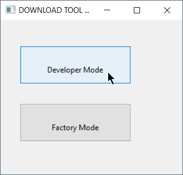
Select “ESP32 DownloadTool”
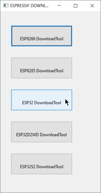
Select the bin file and offset of 0В
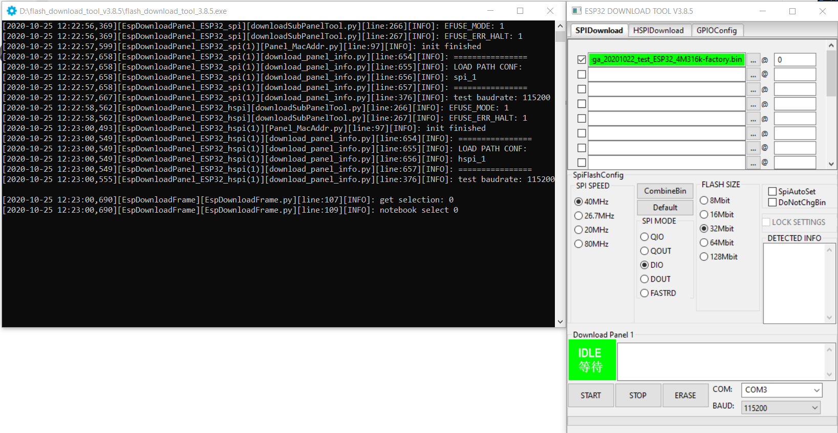
Double check all parameters and start flashing
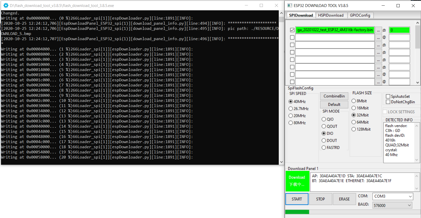
Support us by using one of these alternatives: Patreon Ko-Fi PayPal
© Copyright 2018-2021, ESP Easy.
Created using Sphinx 4.0.2.
Источник
Обновление прошивки ESP-32
Вышел патч с прошивкой ESP32 v.0.2.7, которая исправляет баг с невозможностью подключения коптера по WiFi. Старая версия прошивки перенесена в раздел Загрузки.
Процесс обновления контроллера ESP-32
Перед началом убедитесь:
Проверить можно в Pioneer Station. Для этого подключите квадрокоптер по USB, в правом нижнем углу программы в строчке «Версия АП» должно быть 1.6.7747. При необходимости обновите, Обновление прошивки автопилота
Для обновления прошивки ESP-32, вам понадобиться специальная утилита. Данная инструкция объяснит процесс работы с ней.
- Подключите Пионер Мини к компьютеру через Micro-USB разъем.

- Нажмите кнопку включения, левый светодиод должен начать моргать.
- Скачайте архив ESPTOOL, в нем содержится утилита для прошивки контроллера ESP-32
Рекомендуется запускать на ОС Windows 10.
- Разархивируйте ZIP архив, нажав на него правой кнопкой мыши и выбрав «Извлечь все…».

- Откройте разархивированную папку и запустите из неё файл runiterative.bat
Перед этим вам необходимо закрыть программу Pioneer Station, если она у вас открыта.
В файле par.properties содержатся параметры автопилота. Они загрузятся автоматически, в данной версии программы.
- Дождитесь обновления прошивки ESP-32, она может занимать до 5 минут.

- После появления сообщения «Hard resetting via RTS pin…» закройте утилиту нажатием на «крестик».
Приложение не должно закрываться автоматически, дождитесь надписи указанной выше.

- Перезапустите Пионер Мини нажатием на кнопку включения.

В ESPTOOL 2.0 в случае возникновение аналогичной проблемы надо нажать любую кнопку.
Проверка после обновления
Перед началом убедитесь:
- Что параметры загружены верно.
Проверить загрузили ли вы конкретные параметры 0014 или нет, можно через номер борта, для этого отключите коптер по USB нажав кнопку «подключение», затем заново подключите, если у вас «номер борта» изменился на 2009. (пример на снимке экрана ниже, там 501) При работе с ESPTOOL 2.0 и pioneer_sdk номер борта должен поменяться на 2009.

При необходимости можно загрузить по ссылке ниже или на странице Настройка параметров автопилота Пионера Мини
- Что вы обновили прошивку ESP-32, как описано выше. Для проверки откройте Jump, в расширенных настройках включите отображение отладочной информации. В строке напротив «cur» должна быть надпись [«0.2.7»] или выше.

Также проверить, прошло ли обновление успешно через имя WiFi сети. Если сеть называется «Pioneer_Mini» и после слова «Mini» отсуствует набор случайных цифр и букв, значит обновление не прошло.
После успешного обновления имя сети должно измениться например на «PioneerMini5afg415bb».
- У вас установлено приложение Geoscan Jump последний версии. Номер версии можно проверить в самом приложении в вкладке «Расширенные настройки». Должна быть версия «1.0 16» или выше.

В новой версии Jump кнопку START и STOP необходимо удерживать до тех пор, пока моторы не запустятся/остановятся.
Команда раннего тестирования
Хотите получить доступ к новым возможностям раньше остальных?
Записывайтесь в нашу команду тестирования.
Если вы хотите принять участие, вам необходимо написать в телеграмм аккаунт. Через некоторое время, вам в ответном сообщении вышлют инструкцию для дальнейших действий.
Только для пользователей Пионер Мини!
История обновлений
6 ноября вышла новая прошивка ESP-32. Для корректной работы квадрокоптера, вам обязательно нужно обновить прошивку данного контроллера.
Контроллер ESP-32 отвечает за передачу видеопотока и передачу команд управления с телефона на квадрокоптер.
Новая версия прошивки ESP-32 и обновленный Geoscan Jump, качественно улучшают:
- Скорость передачи видеопотока;
- Увеличено количество кадров в секунду;
- Скорость передачи команд управления;
- Стабильность WiFi соединения;
- Совместимость с большим количеством телефонов.
Новая версия параметров автопилота версии 0014:
- Улучшена стабильность взлета и посадки;
- Квадрокоптер быстрее отключается при переворотах и столкновениях;
- Управление в режимах полета Althold и Stabilize стало более отзывчивым;
- Убран баг с автозапуском LUA скрипта.
© Copyright 2021, Geoscan LTD. Revision 41a23f27 .
Источник


