- General doors and windows
- Object types
- Placing specials
- Globals of positioning I.
- Globals of positioning II.
- Flipping
- General doors and windows
- General Guidelines
- Positioning
- Creation of Door/Window Library Parts
- Rectangular Doors/Windows in Straight Walls
- 3D Related Challenges
- WALLHOLE
- Windows and Doors in GDL
- Index
- 1. Introduction
- 2. Review of requirements
- 3. Positioning
- 4. Usage of the Detail window
- General information
- Oversizing
- 5. Special issues
- Special opening shapes in section
- Scripted reveal in plan view
- Composite windows and doors
- Preparing for automatic dimensions
General doors and windows
Doors and Windows are surely the most often represented types of GDL objects, which implies increased quality and optimality requirements.
To achieve this, the GDL developer must follow lots of general instructions, and has to rely on information coming from ARCHICAD a lot more than in case of other object types.
Doors and windows have to work error free in straight, trapeze and curved walls as well.
This lecture covers the basics of how to create a door/window in a straight wall, and the options you have to think about when creating them.
Note: in ARCHICAD, door and window objects include the wallhole as well.
Object types
Wall openings:
Door, Window, Corner window
Other wall connected types:
Wall niche, Chimney, air shaft, Wall end
To decide the type and let ARCHICAD know it, use special subtypes. Using the right subtype will sort your object into the correspoding Tool category, and enables ARCHICAD to use special positioning features on them: they can be only placed in an existing wall.
Subtypes to use:
- for door: Model Element/Opening/Wall Opening/Door (Wall)
- for window: Model Element/Opening/Wall Opening/Window (Wall)
Placing specials
The object itself has a rotated coordinate system in 3D: 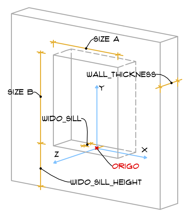
the default position fits the wall, so axes X and Y are parallel to the wall surface, while axis Z is perpendicular to it.
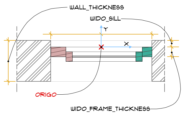
Size “A” is measured on axis X, while size “B” is on the Y axis. The object origo is in the bottom center of the wall opening’s A size, moved on Z axis with sill depth (WIDO_SILL global) value.
This is all very helping when scripting the D/W structure, but gives us some difficulties when dealing with connected structures (such as sunshades, sills, boards etc.)
To check this, create a new window object (watch out for the correct subtype!), and place the following into its 3D script:
Check out the GDL Manual section about Door and Window objects for more about placing.
Globals of positioning I.
The following globals contain information about the position of a window/door inside a wall:
WIDO_SILL: this is the value set in Reveal Depth parameter.
WIDO_FRAME_THICKNESS: this is the value set in “Nominal Frame Thickness” parameter of the window/door (set in in Details/Compatibility options in GDL Editor).
WALL_THICKNESS: the global contains the full depth value of the wall the window/door is placed into.
Globals of positioning II.
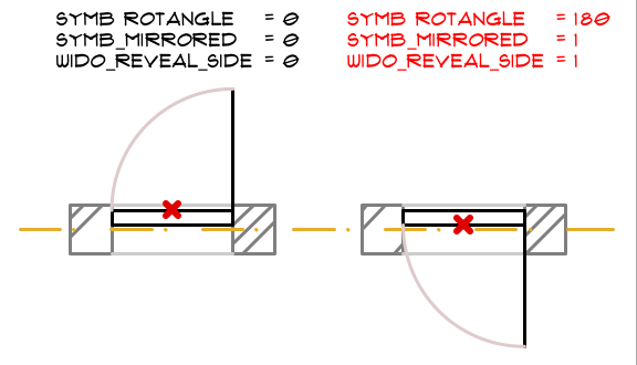
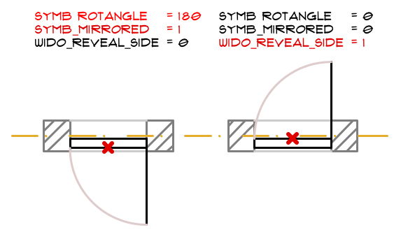
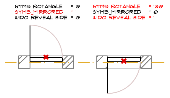
The placing details can be identified by checking the current value of 3 more global variables:
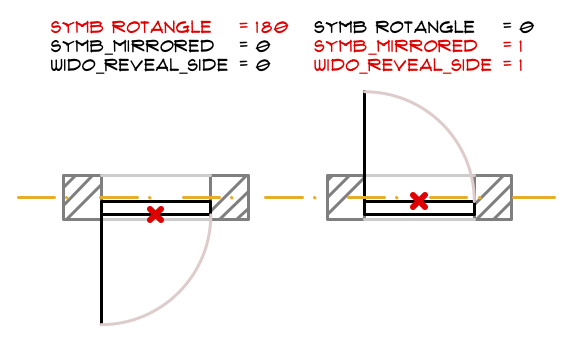
- SYMB_MIRRORED: shows if the object is mirrored to the Y-Z plane in 3D or to the Y axis in 2D
- SYMB_ROTANGLE: shows if the object is “mirrored” by the longitudinal axis of the wall (rotation by 180 degrees)
- WIDO_REVEAL_SIDE: shows if the object is flipped
Flipping
Flipping means turning the window/door inside-out, but keeping its sill depth: the opening-opposite side changes.
ARCHICAD does the following steps when you hit the FLIP button in a door-window object:
Let’s see all 8 combinations depending on how you clicked the window/door into the wall, or what type of editing happened after placing.
Note: these options should be counteracted when dealing with manufacturer content, since a “real” window can not be mirrored or turned inside-out.
Moreso, there are connecting structure parts of a window/door, which parts should not be moved when the object is flipped:
sill, board, sunshade, casing is not supposed to turn inside out, they should stay on their original wall face.
General doors and windows
This section discusses the various special options related to the creation of Door/Window library elements.
General Guidelines
Once a door/window is inserted into a wall, the default position of these library parts’ coordinate system is rotated
so that the x-y plane is vertical and the z axis points horizontally into the wall.
The origin is placed on the bottom center of the wall opening, on the exterior side of the wall.
This way, doors/windows can be easily modeled by elements in the x-y plane. See the illustrations below.
Because of the special behavior of these library parts,
the 2D symbol is generated from a special built-in projection otherwise not accessible by users (an upside-down side view from a 90 degree direction).
The symbol and the 3D shape are fitted to the Door/Window origin by the lower (y) center (x) of the bounding box,
but no adjustment is made along the z axis to enable users to design doors/windows extending beyond the wall in either z direction.
Considering these rules, here are some hints that will help you construct doors/windows that will work properly:
- When constructing the door/window in the floor plan window,
visualize it as if you are looking at it from the inside of the wall it will be inserted into. - Think of the project zero level as the external surface of the wall.
- Elements that should be inside the wall, like the window frame, should be above the zero level.
- Door panels opening to the outside should be below the zero level.
Positioning
A door is correctly defined if its insertion works as follows: clicking to the right of the insertion point means
that the door leaf will open to the same side on the right.
A window is correctly defined if, upon insertion, the side that is clicked corresponds to the outer side.
An opening position can take one of 8 forms.
These are represented by three global variables in GDL:
- mirroring to the Y-Z plane in 3D or to the Y axis in 2D ( SYMB_MIRRORED )
- mirroring by the longitudinal axis of the wall (rotation by 180 degrees: SYMB_ROTANGLE )
- flipping ( WIDO_REVEAL_SIDE )
Usually each part of the window should react in a different way to these conditions.
The specification must be clear on deciding how the parts of the object should,
or should not act.
E.g. a door leaf moves with these transformations, but the cavity closure does not.
To keep the library part consistent, several transformations should be used for these combinations.
When changing the reveal side (flipping), the library part is mirrored and dragged back by the value of the nominal frame thickness.
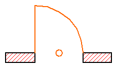
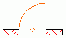
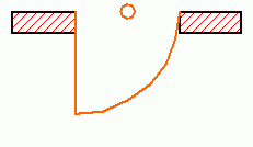
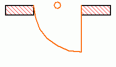
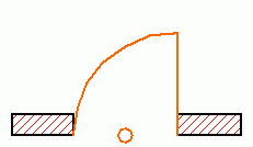
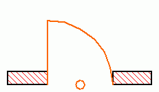
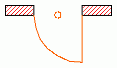
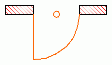
Illustration of the 8 states with a simplified door – the little circle flags the origin.
| Global variables 1. | Example drawing 1. | Global variables 2. | Example drawing 2. | |||||||||||||||||
|---|---|---|---|---|---|---|---|---|---|---|---|---|---|---|---|---|---|---|---|---|
| Global variables | Example drawing |
|---|---|
| WIDO_REVEAL_SIDE = 0 SYMB_MIRRORED = 0 SYMB_ROTANGLE = 0 |  |
| WIDO_REVEAL_SIDE = 0 SYMB_MIRRORED = 1 SYMB_ROTANGLE = 0 |  |
| WIDO_REVEAL_SIDE = 1 SYMB_MIRRORED = 0 SYMB_ROTANGLE = 180 |  |
| WIDO_REVEAL_SIDE = 1 SYMB_MIRRORED = 1 SYMB_ROTANGLE = 180 |  |
| WIDO_REVEAL_SIDE = 1 SYMB_MIRRORED = 0 SYMB_ROTANGLE = 0 |  |
| WIDO_REVEAL_SIDE = 1 SYMB_MIRRORED = 1 SYMB_ROTANGLE = 0 |  |
| WIDO_REVEAL_SIDE = 0 SYMB_MIRRORED = 0 SYMB_ROTANGLE = 180 |  |
| WIDO_REVEAL_SIDE = 0 SYMB_MIRRORED = 1 SYMB_ROTANGLE = 180 |  |
Sample code undoing the automatic transformations done by ArchiCAD:
! 2D script bRotated = round_int (SYMB_ROTANGLE) = 180 if bRotated then rot2 180 endif if SYMB_MIRRORED then mul2 -1, 1 endif if WIDO_REVEAL_SIDE exor bRotated then add2 0, WALL_THICKNESS endif
! 3D script bRotated = round_int (SYMB_ROTANGLE) = 180 if bRotated then roty 180 endif if SYMB_MIRRORED then mulx -1 endif if WIDO_REVEAL_SIDE exor bRotated then addz -WALL_THICKNESS endif
Note that though flipping and mirroring is possible for all doors and windows, it is incorrect in manufacturer libraries where a library part models a real window — which, of course, cannot be turned inside out. In this case the script should undo the mirroring done by ArchiCAD.
4. Usage of the Detail window
General information
The edit boxes accept only 256 characters. This can be circumvented using a parameter here which gets its value in the parameter script.
These edit boxes represent one GDL code line. This implies the following:
- In the definition for oversize and wall inset values, only parameters and global variables can be used as variables, since the definition of variables is impossible.
- Control flow statements cannot be used; you can use logical functions for such purposes.
Clause conversion tips
Original clause → Compressed clause if a -1 It will have no effect on zones (WIDO_REVEAL_SIDE * (WALL_THICKNESS — WIDO_SILL — WIDO_FRAME_THICKNESS) + not(WIDO_REVEAL_SIDE) * WIDO_SILL) * (2 * (abs(GLOB_ELEVATION) The zone will show up on both sides of the frame (see picture below), even in the case of flipping. For windows, it can be used when they are inserted in the wall without any parapet height ( GLOB_ELEVATION = 0 ).
Oversizing
The oversize values have an effect on the size of the rectangular holes cut in the containing wall automatically by ArchiCAD for doors/windows. It can be used, for example, for placing a sunshade’s box above the window; using scripted jambs instead of ArchiCAD jambs and so on. These values must be carefully designed during the specification phase to have a satisfactory result.
5. Special issues
Special opening shapes in section
When special shaped openings are requested try to avoid using filling bodies; use wallhole and wallniche commands instead. Using these, you should be able to crate any wall opening and delve shape.
If you still need a filling body, mind the following:
- Use all attributes of the wall (material, color, pen number etc.)
- Suit the segmentation of the containing wall.
- Care for correct texture mapping ( coor ).
- Special care must be paid to the positioning problems: as the wall filling body should never react to the mirrored, rotated, flipped positions in the same way as the window/door itself, these transformations must be neutralized in the 2D/3D scripts.
Building a special window you cannot use the macros contained in the Basic Library, you have to model your own trim or shading devices. Doing this pay extra attention to correct segmentation and positioning.
Scripted reveal in plan view
A scripted reveal is needed when the one created by Archicad doesn’t fulfill the needs. This way this functionality is an option of the library part in a parameterized form. This may be needed, for example, when the specification orders to omit the jamb in 1:100 scale. The scripted reveal must function for composite wall structures as well, and must react correctly to all positioning — even asymmetric — cases, both in 2D and 3D.
You have two main choices for the user interface:
- use the built-in reveal parameters of Archicad
- omit the built-in reveal parameters and use additional parameters.
In both cases you have to hide the reveals placed by Archicad. In 3D it can be simply done by using a proper wall niche command, in 2D by calling wallhole2 and wallblock2 .
The CavityClosure macro of the Basic Library is implemented according these quidelines.
Composite windows and doors
A window or door consists of many standard elements, like trim, shutter, sill, board, treshold, shading device, frame, sash, etc. The models and control logics of them may not be coded in all openings.
For structures built in the window, you should write a macro and use it in each window/door of your library. You can use the macro set of the Basic Library, too. This solution is needed when there is interaction between the window panel and the special structure — this is the typical case.
For elements which are not in close interaction with the window, you can write an independent object which can be placed on the according point of the opening by the user. F.ex.: shaders, separator columns for window stacking.
For customizable parts consider using the Custom Component Addon, which is shipped wich Archicad.
Preparing for automatic dimensions
You surely want your window and door objects to be dimensioned by Automatic Dimensions and by Interactive Schedule. To achieve this, the object must have hotspots in definite positions.
If you would like to have a dimension on nominal width and height, the object must have 4 hotspots in a vertical plane, with distance A horizontally and B vertically. These hotspots must have own unique IDs. These IDs shouldn’t change when you change the scale or anything. This nominal sizing works with the default hotspot provided by ArchiCAD also.
If you would like to dimension the reveal, wallhole or unit width/height, you need more hotspots with the distance «ac_reveal_width», «ac_reveal_height» or «ac_wallhole_width», «ac_wallhole_height» or «ac_unit_width», «ac_unit_height».
In case your major concern are the dimension lines in the schedule, you can omit these hotspots depending on the GLOB_CONTEXT global. Its value is 6 for scheduling and listing. Interactive Schedule sets the — usually hidden — bShowAddHotspotsForIS parameter to 1 in the LibraryGlobal settings objects in case there is one and it has such a parameters. It can be used for the exact identification of the IS situation. See Library Global View Options section of the Technical Standards for details about Library Globals.
Copyright © 2011 — Graphisoft R&D Software Development Rt. All rights reserved worldwide.
