- GS-iMX-8QM-MEK: Get Started with the i.MX 8QuadMax MEK
- Jump To
- Out of box
- 1.1 Get Familiar with the Board
- 1.2. Insert the SD card (J19)
- 1.3 Connect USB debug cable
- Linux
- Windows
- Windows
- 1.4 Connect the HDMI cable
- 1.5 Boot Switch Setup
- 1.6 Connect Power Supply
- Embedded Linux ®
- 2.1 Overview
- 2.1.1. Download an NXP Linux BSP pre-built image
- 2.1.2 Burn NXP Linux BSP image using Universal Update Utility (UUU)
- Linux ®
- Windows ™
- 2.1.2.1. Install UUU on Linux Distro
- 2.1.2.1.1 Burn the NXP Linux BSP image to the board
- 2.1.2.2. Install UUU on Windows
- 2.1.2.2.1. Burn the NXP Linux BSP image to the board
- Explore
- 3.1 Explore the documentation
- 3.1.1 Board documentation
- 3.1.2. SoC documentation
- 3.1.3. Software documentation
- Yocto Linux BSP Ver.A User Guide for iMX8 series
- Contents
- Getting Started
- Conventions
- Docker install and setting
- To install Docker Engine on your platform
- To pull ubuntu 18.04 image from Docker Hub
- To create container
- Get BSP
- Download_BSP_From_GitHub
- Copy BSP tarball to Container
- Downloads tarball
- Introducing BSP
- Yocto Linux BSP Ver.9 User Guide for iMX8 series
- Contents
- Getting Started
- Conventions
- Docker install and setting
- To install Docker Engine on your platform
- To pull ubuntu 18.04 image from Docker Hub
- To create container
- Get BSP
- Download_BSP_From_GitHub
- Copy BSP tarball to Container
- Downloads tarball
- Introducing BSP
- Naming Rule
- BSP Content
- Build Instructions
- To create one new build environment
- To continue an exist build environment
- To build recovery image for OTA
- To build sdcard image
- To build toolchain installer
- To build bootloader
- To build linux kernel
- Creating boot-up on-board flash from prebuilt image
- To create one boot-up SD card
- Creating boot-up on-board flash from built sdcard image
- To create one boot-up SD card
- Debug console information
- Preparing for hardware device
- Preparing for software tool
- One step build image
- Customization
- Package addition
- To add tcf-agent & openssh-sftp-server
- To add chromium browser
- To add QtWebEngine
- Setting up SDK
- Setting up cross compiling environment
- Build U-Boot in standalone environment
- Config u-boot
- Build u-boot
- Build imx-boot image by using imx-mkimage
- Replace imx-boot
- Building & updating kernel/modules/dtb manually
- Copy BSP tarball to Container
- Config kernel
- Replace kernel & dts
- Improve boot speed
- System Recovery
- Recover by SD card
- Recover by UUU tool
- Package List
- Device Tree Source file select
- ROM-5721
- ROM-5720
- ROM-5620
- ROM-3620
- ROM-7720
- Burn-in Test
- About DB5901 bottom board setting
- The disable pin of PCIE
GS-iMX-8QM-MEK: Get Started with the i.MX 8QuadMax MEK
Jump To
Out of box
The following section describes the steps to boot the i.MX 8QuadMax MEK.
Development kit contains:
- i.MX 8QuadMax MEK board for smart devices
- USB cable (micro-B to standard-A)
- Cable -Assembly, USB 2.0 Type-A Male, USB Type-C Male, Shielded, 1m
- 12 V/11.5 A universal power supply
- Quick Start Guide
- 16 GB SD card with bootable operating system demonstration image
1.1 Get Familiar with the Board
Figure 1. i.MX 8QuadMax MEK front
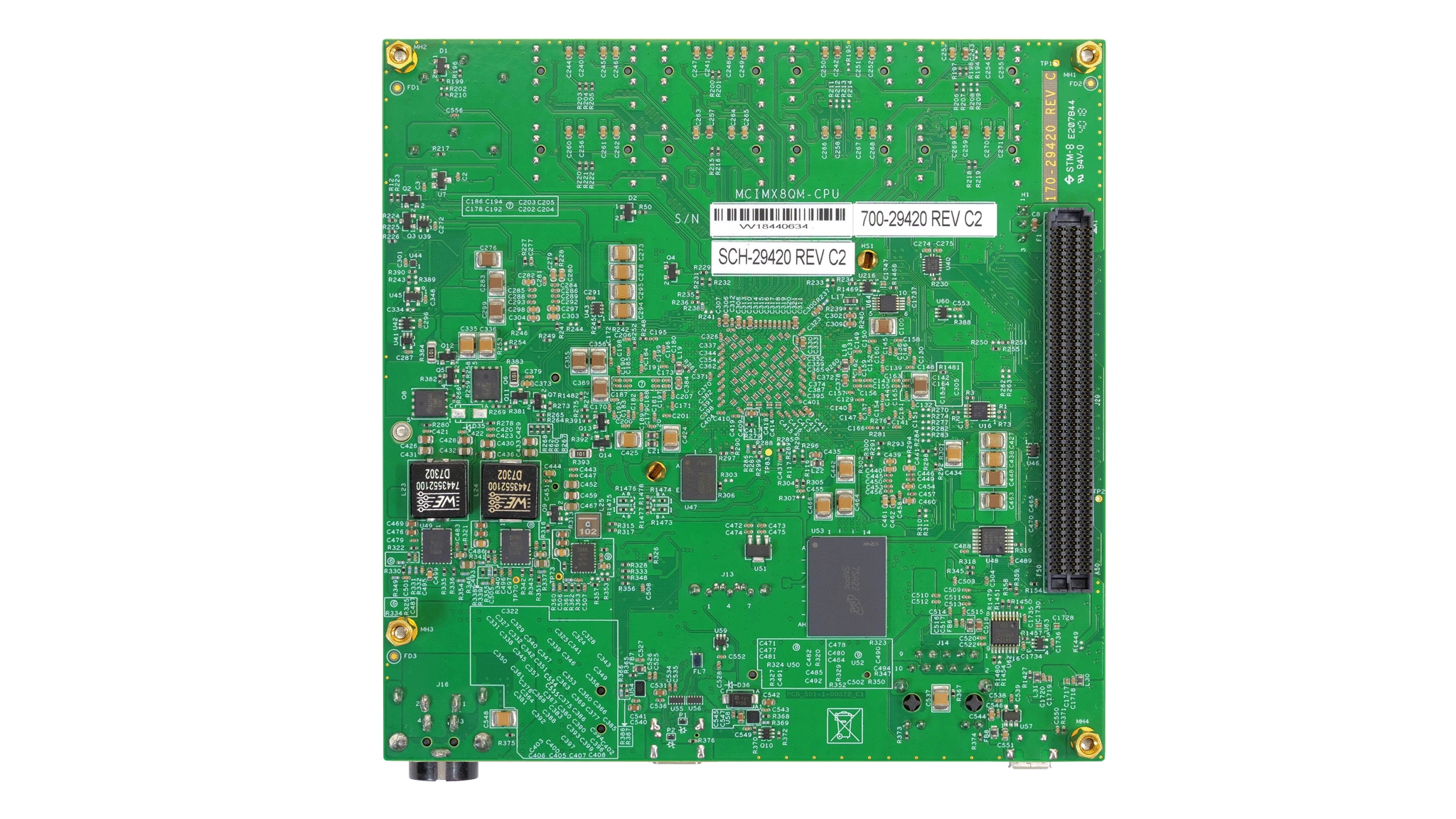
Figure 2. i.MX 8QuadMax MEK back
1.2. Insert the SD card (J19)
The kit includes an SD card with a pre-built NXP Linux binary demo image. Without modifying the binary inside the SD card, booting from this SD card provides a default system with certain features for building other applications on top of Linux. The software is described in the following sections.
1.3 Connect USB debug cable
Connect the micro-B end of the supplied USB cable into Debug UART port J18 . Connect the other end of the cable to a host computer.
If you are not sure about how to use a terminal application, try one of the following tutorials depending on the operating system of the host machine:
Linux
Windows
Windows
1.4 Connect the HDMI cable
To see the user interface provided with the image binary connect a monitor via the HDMI connector ( J6 ).
1.5 Boot Switch Setup
Click here to see the Boot Switch Setup
1.6 Connect Power Supply
Connect the power supply cable to the power connector ( J16 ).
Power the board by flipping the switch ( SW1 ).
The processor starts executing from the on-chip ROM code. With the default boot switch setup, the code reads the fuses to define the media where it is expected to have a bootable image. After it finds a bootable image, the U-Boot execution should begin automatically.
Information is printed in the smaller number serial console for the Cortex ® -A53. If you do not stop the U-Boot process, it continues to boot the Linux kernel.
Embedded Linux ®
This section is applicable ONLY if attempting to load a Linux operating system on the board.
The i.MX Linux Board Support Package (BSP) is a collection of binary files, source code, and support files that are used to boot an Embedded Linux image on a specific i.MX development platform.
Current releases of Linux binary demo files can be found on the i.MX Linux download page. Additional documentation is available in the i.MX Linux documentation bundle under the Linux sections of the i.MX Software and Development Tool.
2.1 Overview
Before the Linux OS kernel can boot on an i.MX board, the Linux kernel is loaded to a boot device (SD card, eMMC and so on) and the boot switches are set to boot that device.
There are various ways to download the Linux BSP image for different boards and boot devices.
For this getting started guide, only a few methods to transfer the Linux BSP image to an SD card are listed. Experienced Linux developers can explore other options.
2.1.1. Download an NXP Linux BSP pre-built image
The latest pre-built images for the i.MX 8QuadMax MEK are available on the Linux download page under the most current version on Linux.
The pre-built NXP Linux binary demo image provides a typical system and basic set of features for using and evaluating the processor. Without modifying the system, the users can evaluate hardware interfaces, test SoC features, and run user space applications.
When more flexibility is desired, an SD card can be loaded with individual components (boot loader, kernel, dtb file, and rootfs file) one-by-one or the .sdcard image is loaded and the individual parts are overwritten with the specific components.
2.1.2 Burn NXP Linux BSP image using Universal Update Utility (UUU)
In addition to the connections from Out of box chapter, connect the J17 to the host machine using the proper USB cable.
Turn off the board. Consult Boot switch setup and configure the board to boot on SDP (Serial Download Protocol) mode.
Depending on the OS used in the host machine, the way to transfer the Linux BSP image onto an SD card can vary.
Choose an option below for detailed instructions:
Linux ®
Windows ™
2.1.2.1. Install UUU on Linux Distro
Download the latest stable files from UUU GitHub page. An extensive tutorial for UUU can be found in https://github.com/NXPmicro/mfgtools/wiki.
- uuu
- libusb1 (via apt-get or any other package manager)
2.1.2.1.1 Burn the NXP Linux BSP image to the board
By default, this procedure flashes the image to the SD card flash. Check the UUU GitHub page for reference on how to flash the image to other devices.
Open a terminal application and change directory to the location where uuu and the latest Linux distribution for i.MX 8QuadMax MEK are located. Add execution permission to the uuu file and execute it. Uuu waits for the USB device to connect
$ sudo ./uuu _images_ .zip
Turn on the board, uuu starts to copy the images to the board.
When it finishes, turn off the board, and consult Boot switch setup to configure the board to boot from SDcard.
2.1.2.2. Install UUU on Windows
Download the latest stable files from UUU GitHub page. An extensive tutorial for UUU can be found in https://github.com/NXPmicro/mfgtools/wiki.
- uuu.exe
- Serial USB drivers (depending on your board and Windows installation)
2.1.2.2.1. Burn the NXP Linux BSP image to the board
By default, this procedure flashes the image to the SD card flash. Check the UUU GitHub page for reference on how to flash the image to other devices.
Open the command prompt application and navigate to the directory where the uuu.exe file and the Linux release for the i.MX 8QuadMax MEK are located.
> uuu.exe _images_ .zip
Turn on the board, uuu starts to copy the images to the board.
When it finishes, turn off the board, and consult Boot switch setup to configure the board to boot from SDcard.
Explore
3.1 Explore the documentation
When working with embedded systems, it is important to bear in mind that the documentation is wide and diverse. It is common to have different levels of documentation. The i.MX 8QuadMax MEK board has some documents. However, this board’s processor is i.MX 8QuadMax which is documented with SoC level documents. The BSPs available are documented with the BSP level documents.
Choose an option below for related documents:
3.1.1 Board documentation
In the case of i.MX 8QuadMax MEK the following documents are available.
Table 2. List of i.MX 8QuadMax MEK board-related documents
| Document | Description |
| Board Schematics | The i.MX 8QuadMax MEK electric schematic files. |
| i.MX 8QuadMax MEK Hardware User Guide | The purpose of this document is to help hardware engineers design and test their imx8qm series processor-based designs. It provides information on board layout recommendations, design checklists to ensure first-pass success, and ways to avoid board bring-up problems. It also provides information on board-level testing and simulation such as using BSDL for board-level testing, using the IBIS model for electrical integrity simulation and more. |
3.1.2. SoC documentation
In the case of i.MX 8QuadMax SoC the following documents are available.
Table 3. List of i.MX 8QuadMax chip-related documents
| Document | Description |
| i.MX 8QuadMax DataSheet | Describes the SoC physical and electrical characteristics, the part number meaning. |
| i.MX 8QuadMax Reference Manual | Lists what the SoC supports, the registers and the memory map. Describes the features, workflow, the boot flow, and the meaning of each register’s bits. |
| i.MX 8QuadMax ERRATA | List the hardware issues for that SoC. It may be an Arm core or an i.MX core issue. It may or may not have a workaround. |
| i.MX 8QuadMax Security Reference Manual | Sing-in to request access to the i.MX 8QuadMax Security Reference Manual. The link to download is sent in the email. |
3.1.3. Software documentation
For i.MX 8QuadMax MEK the following BSPs are available.
- Linux Kernel distribution using the Yocto Project: For details, see the documentation in i.MX 8QuadMax MEK BSP Linux documents
- Android: For details, see the documentation in i.MX 8QuadMax MEK BSP Android documents
Each BSP has a set of documents, in the next tables all the BSP documentation is described. The order the documents appear in the table is the recommended read order.
Источник
Yocto Linux BSP Ver.A User Guide for iMX8 series
Contents
Getting Started
Conventions
$ : compressed prebuilt image (*.img.gz)
$ : container name (e.g. imx8LBVA0016)
$ : BSP tarball (*.tgz)
$ : home directory of the BSP
$ : build directory (e.g. build_x11)
mx8mq for iMX8M Dual Core
mx8mm for iMX8MM
mx8mp for iMX8MP
mx8qm for iMX8QM
mx8qxp for iMX8QXP
imx8mq / imx8mm / imx8qm /imx8qxp /imx8mp
$ : available target boards list below
rom5720
rom5721
rom7720
rom5620
rom3620
rom5722
rsb3720
for example,
imx8mqrom5720a1 for ROM-5720 A1
imx8qmrom7720a1 for ROM-7720 A1
imx8qxprom5620a1 for ROM-5620 A1
imx8qxprom3620a1 for ROM-3620 A1
imx8mmrom5721a1 for ROM-5721 A1
imx8mprom5722a1 for ROM-5722 A1
imx8mprsb3720a1 for RSB-3720 A1
You can also use the command below to check supported machines on BSP $ source setup-environment
$ : device name of SD card in Linux (e.g. /dev/sdf)
$ : sdcard image built by bitbake (*.sdcard.bz2)
$ : host workspace folders
$ :u-boot version(e.g. 2016.03)
$ : linux kernel version(e.g. 4.14.98)
$ : toolchain installed directory(e.g. /opt/fsl-imx-x11/4.1.15-2.0.0)
debug console / serial console
serial terminal program (e.g. minicom, putty, teraterm . ) that serial port is configured to 115200 8N1
terminal program (e.g. gnome-terminal, xfce4-terminal . )
Docker install and setting
If you don’t have docker in your system, then you can follow the below steps to install docker and run it first.
To install Docker Engine on your platform
To pull ubuntu 18.04 image from Docker Hub
To create container
Get BSP
Download_BSP_From_GitHub
Copy BSP tarball to Container
Follow the steps below:
1.Exit container and back to local machine
2.Copy BSP tarball to $
3.Back to container
4.Unpack BSP tarball
Downloads tarball
Follow the steps below:
1.Exit container and back to local machine
2.Copy Downloads tarball to $
3.Back to container
4.Unpack Downloads tarball
5.make link to downloads folder
Introducing BSP
one or more build directories, and a set of scripts used to set up the environment.
The recipes used to build the project come from both the community and Advantech. The Yocto Project layers are downloaded
to the sources directory. This sets up the recipes that are used to build the project.
Источник
Yocto Linux BSP Ver.9 User Guide for iMX8 series
Contents
Getting Started
Conventions
$ : compressed prebuilt image (*.img.gz)
$ : container name (e.g. imx9LBV90016)
$ : BSP tarball (*.tgz)
$ : home directory of the BSP
$ : build directory (e.g. build_x11)
mx8mq for iMX8M Dual Core
mx8mm for iMX8MM
mx8qm for iMX8QM
mx8qxp for iMX8QXP
imx8mq / imx8mm / imx8qm /imx8qxp
$ : available target boards list below
rom5720
rom5721
rom7720
rom5620
rom3620
for example,
imx8mqrom5720a1 for ROM-5720 A1
imx8qmrom7720a1 for ROM-7720 A1
imx8qxprom5620a1 for ROM-5620 A1
imx8mmrom5721a1 for ROM-5721 A1
imx8qxprom3620a1 for ROM-3620 A1
You can also use the command below to check supported machines on BSP $ source setup-environment
$ : device name of SD card in Linux (e.g. /dev/sdf)
$ : sdcard image built by bitbake (*.sdcard.bz2)
$ : host workspace folders
$ :u-boot version(e.g. 2016.03)
$ : linux kernel version(e.g. 4.14.98)
$ : toolchain installed directory(e.g. /opt/fsl-imx-x11/4.1.15-2.0.0)
debug console / serial console
serial terminal program (e.g. minicom, putty, teraterm . ) that serial port is configured to 115200 8N1
terminal program (e.g. gnome-terminal, xfce4-terminal . )
Docker install and setting
If you don’t have docker in your system, then you can follow the below steps to install docker and run it first.
To install Docker Engine on your platform
To pull ubuntu 18.04 image from Docker Hub
To create container
Get BSP
Download_BSP_From_GitHub
Copy BSP tarball to Container
Follow the steps below:
1.Exit container and back to local machine
2.Copy BSP tarball to $
3.Back to container
4.Unpack BSP tarball
Downloads tarball
Follow the steps below:
1.Exit container and back to local machine
2.Copy Downloads tarball to $
3.Back to container
4.Unpack Downloads tarball
5.make link to downloads folder
Introducing BSP
one or more build directories, and a set of scripts used to set up the environment.
The recipes used to build the project come from both the community and Advantech. The Yocto Project layers are downloaded
to the sources directory. This sets up the recipes that are used to build the project.
Naming Rule
For example, Yocto image name: ‘5720A1AIM20LIV90010_iMX8M_2019-08-27.img.gz’
which «5720A1» stands for ROM-5720 A1
«LI» is acronym for prebuilt L inux I mage
BSP Content
Build Instructions
To create one new build environment
To continue an exist build environment
To build recovery image for OTA
To build sdcard image
To build toolchain installer
To build bootloader
To build linux kernel
Creating boot-up on-board flash from prebuilt image
To create one boot-up SD card
Creating boot-up on-board flash from built sdcard image
To create one boot-up SD card
Debug console information
If you want to see debug message from device, you need to prepare for hardware device and software tool.
Preparing for hardware device
- The following URL provides information about the debug port slot and the debug port line for each device
Preparing for software tool
- You need to prepare the debug console tool. For example: «minicom» tool or «putty» tool.
- Baud rate: 115200
One step build image
Our machine must be pre-installed docker
Download the following script can quickly build our image.
Our image will be in workspace folder.
Customization
Package addition
To add tcf-agent & openssh-sftp-server
To add chromium browser
To add QtWebEngine
Setting up SDK
Setting up cross compiling environment
Build U-Boot in standalone environment
Config u-boot
Build u-boot
Build imx-boot image by using imx-mkimage
Get imx-boot tarball from our server Here we take rom5721 as an example:
In this folder , we have two script as below: Copy necessary files to imx-mkimage folder
Make imx-boot image
Replace imx-boot
Building & updating kernel/modules/dtb manually
First, set up the cross compiling environment!
Copy BSP tarball to Container
Refer to Copy_BSP_tarball_to_Container , copy kernel tarball to $
change owner & unpack tarball
Config kernel

run command then rebuild
The kernel image file, Image, is located in the directory «./arch/arm64/boot/». Start building kernel modules Copy all modules to a temporary rootfs directory, «
/temp/rootfs» Building device tree blob The device tree blob, $ — $ — $ .dtb, is located in the directory «./arch/arm64/boot/dts/freescale/». Note: ./build_x11/tmp/work-shared/imx8qxprom5620a1/kernel-source/arch/arm64/boot/dts/freescale/imx8qxp-rom5620-a1.dts
Replace kernel & dts
Improve boot speed
We can cancel the bootdelay time by setting bootloader environment value.
Disable debug message output can also improve boot speed
Disable kernel message
Disable debug port
(1) Yocto machine setting:
modify the meta-fsl-imx/conf/machine/$
(2) Uboot parameter setting:
- For the imx8mq, imx8mm, imx8mp:
- For the imx8qm, imx8qxp:
- Rootfs
TBD
- Services
1. Using systemctl disable remove ,we can remove unnecessary services.
System Recovery
This section provides detail procedures of restoring the eMMC image.
If you destroy the onboard flash image by accident, you can recover a system following these steps.
Recover by SD card
1.Copy 5720A1AIM20LIV90022_iMX8M_flash_tool.tgz package to your desktop.
2.Insert SD card to PC
3.Make a bootable sd card
4.Insert SD card and copy 5720A1AIM20LIV90022_iMX8M_flash_tool to USB disk
5.Insert USB disk and SD card then Boot from SD
6.Enter usb disk folder, make a bootable emmc
Recover by UUU tool
2.Create a folder with files as below:
- We can download image from official build folder(https://www.dropbox.com/sh/w271m51tuoajvbp/AAD6KM2uu-ONRUXCLKL8y4hia?dl=0)
- rootfs.sdcard in 5620A1AIM20LIV90135_iMX8X_flash_tool.tgz
- imx-boot in 5620A1AIM20LIV90135_iMX8X_imx-boot.tgz
3.Connect USB OTG cable from PC to device
4.Set SW1 to Recovery mode, then power on
- ROM5720/ROM5721/ROM5620: 1,2,3-off, 4-on
- ROM7720: 1,2,3,4,5,6-off or 1,2,4,5,6-off, 3-on
5.Perform the following command:
PS.If you want to burn uboot to mmcblk0 instead of mmcblk0boot0, u-boot must be updated to version 20191101,
6.uuu tool will start recovery image to emmc.
7.If we want to burn separately into emmc
Package List
In BSP, list all packages which will be built in the image
Show all recipes (include non-installed packages)
You can also check $ /tmp/deploy/images/ $ /fsl-image-qt5-validation-imx- $ .manifest
It will show the same content with checking by rpm tool on target board.
On target board, list all packages by rpm tool
Device Tree Source file select
We can setup different dts file on bootloader to enable different devices.
ROM-5721
- Display
- DSI to LVDS
- g070vw01
- adv-imx8mm-rom5721-a1.dtb
- g150xgel05
- adv-imx8mm-rom5721-a1-dsi2lvds-g150xgel05.dtb
- g215hvn01
- adv-imx8mm-rom5721-a1-dsi2lvds-g215hvn01.dtb
- g070vw01
- DSI to DP
- adv-imx8mm-rom5721-a1-dsi2dp.dtb
- DSI to HDMI
- adv-imx8mm-rom5721-a1-adv7535.dtb
- DSI
- auog101uan02
- adv-imx8mm-rom5721-a1-auog101uan02.dtb
- auog101uan02
- DSI to LVDS
- M.2 SDIO
- Adjust CN43
CN48
- adv-imx8mm-rom5721-a1-m2-sdio.dtb
- Adjust CN43
- M.2 I2S
- adv-imx8mm-rom5721-a1-m2-i2s.dtb
ROM-5720
- Display
- DSI to HDMI
- adv-imx8mq-rom5720-a1-dcss-adv7535-b3.dtb
- adv-imx8mq-rom5720-a1-lcdif-adv7535.dtb
- DSI
- auog101uan02
- adv-imx8mq-rom5720-a1-dcss-auog101uan02.dtb
- auog101uan02
- Dual Display
- DSI to HDMI + HDMI
- adv-imx8mq-rom5720-a1-dual-display.dtb
- DSI to HDMI + HDMI
- DSI to HDMI
- M.2 SDIO
- Adjust CN43
CN48
- adv-imx8mq-rom5720-a1-m2-sdio.dtb
- Adjust CN43
- M.2 I2S
- adv-imx8mq-rom5720-a1-m2-i2s.dtb
ROM-5620
- Display
- LVDS
- g070vw01
- adv-imx8mxp-rom5620-a1.dtb
- g150xgel05
- adv-imx8qxp-rom5620-a1-lvds-chimei.dtb
- g215hvn01
- adv-imx8qxp-rom5620-a1-lvds-dual.dtb
- g070vw01
- LVDS to HDMI
- adv-imx8qxp-rom5620-a1-hdmi-bridge.dtb
- DSI to HDMI
- adv-imx8qxp-rom5620-a1-hdmi-bridge.dtb
- DSI
- auog101uan02
- adv-imx8qxp-rom5620-a1-auog101uan02.dtb
- auog101uan02
- LVDS
- M.2 SDIO
- Adjust CN43
CN48
- adv-imx8qxp-rom5620-a1-m2-sdio.dtb
- Adjust CN43
- 2-nd QSPI
- adv-imx8qxp-rom5620-a1-qspi-b.dtb
ROM-3620
- Display
- LVDS
- g070vw01
- adv-imx8mxp-rom3620-a1.dtb
- g150xgel05
- adv-imx8qxp-rom3620-a1-lvds-chimei.dtb
- g215hvn01
- adv-imx8qxp-rom3620-a1-lvds-dual.dtb
- g070vw01
- DSI to HDMI
- adv-imx8qxp-rom3620-a1-hdmi-bridge.dtb
- DSI
- auog101uan02
- adv-imx8qxp-rom3620-a1-auog101uan02.dtb
- auog101uan02
- LVDS
ROM-7720
- Display
- HDMI
- adv-imx8qm-rom7720-a1.dtb
- LVDS
- g070vw01
- adv-imx8qm-rom7720-a1_lvds0.dtb
- adv-imx8qm-rom7720-a1_lvds1.dtb
- g215hvn01
- adv-imx8qm-rom7720-a1_lvds_dual.dtb
- g070vw01
- HDMI + LVDS
- HDMI + g070vw01
- adv-imx8qm-rom7720-a1_hdmi_lvds0.dtb
- adv-imx8qm-rom7720-a1_hdmi_lvds1.dtb
- HDMI + g215hvn01
- adv-imx8qm-rom7720-a1_hdmi_lvds_dual.dtb
- HDMI + g070vw01
- LVDS to HDMI
- adv-imx8qm-rom7720-a1-it6263.dtb
- HDMI
- Audio Codec
- adv-imx8qm-rom7720-a1-sgtl5000.dtb
Burn-in Test
When running the burn-in test, the CPU, GPU and VPU are running in turns. It is not recommended to run three at the same time.
About DB5901 bottom board setting
The disable pin of PCIE
On DB5901 bottom board, the disable pin is connect to gpio expander(tca9538)


You should config disable pin follow your bottom board.
If the disable pin is not set correctly, the pcie may not enable.
We remove the disable pin setting by default.
Источник


