То, что здесь написано — НЕ IPSec VPN. И никогда им не станет. Для IPSec VPN никаких дополнительных интерфейсов, кроме уже присутствующих в системе, создавать не надо — а тут конфигурируется Dialer1.
Курим документацию до тех пор, пока не станут ясны различия между:
1. IPSec AH Transport Mode; 2. IPSec ESP Transport Mode; 3. IPSec AH Tunnel Mode; 4. IPSec ESP Tunnel Mode; 5. GRE Tunnel protected by IPSec AH Transport Mode; 6. GRE Tunnel protected by IPSec ESP Transport Mode; 7. GRE Tunnel protected by IPSec AH Tunnel Mode; 8. GRE Tunnel protected by IPSec ESP Tunnel Mode; 9. PPP over TCP protected by IPSec AH Transport Mode; 10. PPP over TCP protected by IPSec ESP Transport Mode; 11. PPP over TCP protected by IPSec AH Tunnel Mode; 12. PPP over TCP protected by IPSec ESP Tunnel Mode; 13. L2TP over UDP protected by IPSec AH Tunnel Mode (AH VPDN); 14. L2TP over UDP protected by IPSec ESP Tunnel Mode (ESP VPDN);
Все это можно сделать на связке «Линукс Циска». Из них VPN’ами будут варианты №№ 3-14, а IPSec VPN’ами будут варианты №№ 3 и 4.
4.4 , ilia kuliev ( ok ), 09:51, 03/06/2008 [^] [^^] [^^^] [ответить]
+ / –
>Все это можно сделать на связке «Линукс Циска». Из них VPN’ами будут варианты №№ 3-14, а IPSec VPN’ами будут варианты №№ 3 и 4.
До этого места все было верно, а вот начиная с процитированного — это из вашего личного определния VPN ? Или из общепринятого? Если из общепринятого, приведите пожалуйста ссылку на собственно определение. Спасибо.
> До этого места все было верно, а вот начиная с процитированного — это из вашего личного > определния VPN ? Или из общепринятого?
Я, честно говоря, не вполне понимаю, что такое «общепринятое определение VPN». Если http://en.wikipedia.org/wiki/VPN — это определение можно считать общепринятым, то, согласно тому, что: «. The link-layer protocols of the virtual network are said to be tunneled through the larger network when this is the case,» — случаи 1 и 2 под определение VPN не попадают, так как это transport mode. Остальное все (т.е, случаи 3-14) — туннели.
А вот что касается того, что считать IPSec VPN’ом, а что не считать — так это уже according to Cisco. Она называет, правда, IPSec Native такие туннели. А остальные — IPSec/GRE или IPSec/PPP.
>[оверквотинг удален] >9. PPP over TCP protected by IPSec AH Transport Mode; >10. PPP over TCP protected by IPSec ESP Transport Mode; >11. PPP over TCP protected by IPSec AH Tunnel Mode; >12. PPP over TCP protected by IPSec ESP Tunnel Mode; >13. L2TP over UDP protected by IPSec AH Tunnel Mode (AH VPDN); > >14. L2TP over UDP protected by IPSec ESP Tunnel Mode (ESP VPDN); > > >Все это можно сделать на связке «Линукс Циска». Из них VPN’ами будут варианты №№ 3-14, а IPSec VPN’ами будут варианты №№ 3 и 4.
для особо деревянных на схеме указано что подключение к сети по pppoe его без dialer не сделать. а крипто мап можно применить хоть к loopback’у/
Источник
Configure IKEv1 IPsec Site-to-Site Tunnels with the ASDM or CLI on the ASA
Available Languages
Download Options
Contents
Introduction
This document describes how to configure an Internet Key Exchange version 1 (IKEv1) IPsec site-to-site tunnel between a Cisco 5515-X Series Adaptive Security Appliance (ASA) that runs software Version 9.2.x and a Cisco 5510 Series ASA that runs software Version 8.2.x.
Prerequisites
Requirements
Cisco recommends that these requirements be met before you attempt the configuration that is described in this document:
The end-to-end IP connectivity must be established.
These protocols must be allowed:
User Datagram Protocol (UDP) 500 and 4500 for the IPsec control plane
Encapsulating Security Payload (ESP) IP Protocol 50 for the IPsec data plane
Components Used
The information in this document is based on these software and hardware versions:
Cisco 5510 Series ASA that runs software Version 8.2
Cisco 5515-X ASA that runs the software Version 9.2
The information in this document was created from the devices in a specific lab environment. All of the devices used in this document started with a cleared (default) configuration. If your network is live, make sure that you understand the potential impact of any command.
Configure
This section describes how to configure the site-to-site VPN tunnel via the Adaptive Security Device Manager (ASDM) VPN wizard or via the CLI.
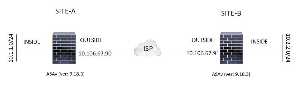
Network Diagram
This is the topology that is used for the examples throughout this document:
Configure Via the ASDM VPN Wizard
Complete these steps in order to set up the site-to-site VPN tunnel via the ASDM wizard:
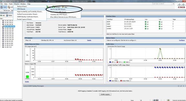
Open the ASDM and navigate to Wizards > VPN Wizards > Site-to-site VPN Wizard:
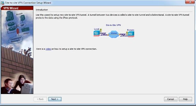
Click Next once you reach the wizard home page:
Note: The most recent ASDM versions provide a link to a video that explains this configuration.
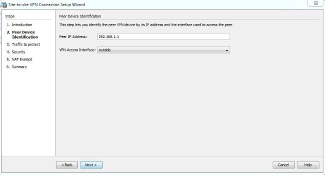
Configure the peer IP address. In this example, the peer IP address is set to 192.168.1.1 on Site B. If you configure the peer IP address on Site A, it must be changed to 172.16.1.1. The interface through which the remote end can be reached is also specified. Click Next once complete.
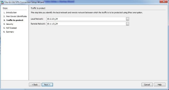
Configure the local and remote networks (traffic source and destination). This image shows the configuration for Site B (the reverse applies for Site A):
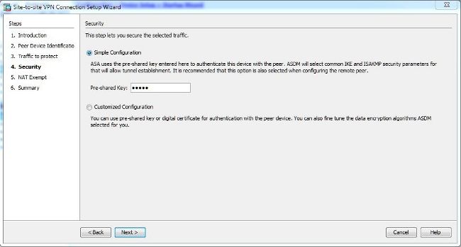
On the Security page, configure the pre-shared key (it must match on both of the ends). Click Next once complete.
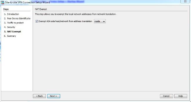
Configure the source interface for the traffic on the ASA. The ASDM automatically creates the Network Address Translation (NAT) rule based on the ASA version and pushes it with the rest of the configuration in the final step.
Note: For the example that is used in this document, inside is the source of the traffic.
The wizard now provides a summary of the configuration that will be pushed to the ASA. Review and verify the configuration settings, and then click Finish.
Configure Via the CLI
This section describes how to configure the IKEv1 IPsec site-to-site tunnel via the CLI.
Configure Site B for ASA Versions 8.4 and Later
In ASA Versions 8.4 and later, support for both IKEv1 and Internet Key Exchange version 2 (IKEv2) was introduced.
Tip: For more information about the differences between the two versions, refer to the Why migrate to IKEv2? section of the Swift Migration of IKEv1 to IKEv2 L2L Tunnel Configuration on ASA 8.4 Code Cisco document.
Tip: For an IKEv2 configuration example with the ASA, refer to the Site-to-Site IKEv2 Tunnel between ASA and Router Configuration Examples Cisco document.
Phase 1 (IKEv1)
Complete these steps for the Phase 1 configuration:
Enter this command into the CLI in order to enable IKEv1 on the outside interface:
Create an IKEv1 policy that defines the algorithms/methods to be used for hashing, authentication, Diffie-Hellman group, lifetime, and encryption:
Create a tunnel group under the IPsec attributes and configure the peer IP address and the tunnel pre-shared key:
Phase 2 (IPsec)
Complete these steps for the Phase 2 configuration:
Create an access list that defines the traffic to be encrypted and tunneled. In this example, the traffic of interest is the traffic from the tunnel that is sourced from the 10.2.2.0 subnet to the 10.1.1.0. It can contain multiple entries if there are multiple subnets involved between the sites.
In Versions 8.4 and later, objects or object groups can be created that serve as containers for the networks, subnets, host IP addresses, or multiple objects. Create two objects that have the local and remote subnets and use them for both the crypto Access Control List (ACL) and the NAT statements.
Configure the Transform Set (TS), which must involve the keyword IKEv1. An identical TS must be created on the remote end as well.
Configure the crypto map, which contains these components:
The peer IP address
The defined access list that contains the traffic of interest
An optional Perfect Forward Secrecy (PFS) setting, which creates a new pair of Diffie-Hellman keys that are used in order to protect the data (both sides must be PFS-enabled before Phase 2 comes up)
Apply the crypto map on the outside interface:
NAT Exemption
Ensure that the VPN traffic is not subjected to any other NAT rule. This is the NAT rule that is used:
Note: When multiple subnets are used, you must create object groups with all of the source and destination subnets and use them in the NAT rule.
Complete Sample Configuration
Here is the complete configuration for Site B:
Configure Site A for ASA Versions 8.2 and Earlier
This section describes how to configure Site A for ASA Versions 8.2 and earlier.
Phase 1 (ISAKMP)
Complete these steps for the Phase 1 configuration:
Enter this command into the CLI in order to enable Internet Security Association and Key Management Protocol (ISAKMP) on the outside interface:
Note: Because multiple versions of IKE (IKEv1 and IKEv2) are not supported any longer, the ISAKMP is used in order to refer to Phase 1.
Create an ISAKMP policy that defines the algorithms/methods to be used in order to build Phase 1.
Note: In this example configuration, the keyword IKEv1 from Version 9.x is replaced with ISAKMP.
Create a tunnel group for the peer IP address (external IP address of 5515) with the pre-shared key:
Phase 2 (IPsec)
Complete these steps for the Phase 2 configuration:
Similar to the configuration in Version 9.x, you must create an extended access list in order to define the traffic of interest.
Define a TS that contains all of the available encryption and hashing algorithms (offered issues have a question mark). Ensure that it is identical to that which was configured on the other side.
Configure a crypto map, which contains these components:
The peer IP address
The defined access list that contains the traffic of interest
An optional PFS setting, which creates a new pair of Diffie-Hellman keys that are used in order to protect the data (both sides must be PFS-enabled so that Phase 2 comes up)
Apply the crypto map on the outside interface:
NAT Exemption
Create an access list that defines the traffic to be exempted from the NAT checks. In this version, it appears similar to the access list that you defined for the traffic of interest:
When multiple subnets are used, add another line to the same access list:
The access list is used with the NAT, as shown here:
Note: The inside here refers to the name of the inside interface on which the ASA receives the traffic that matches the access list.
Complete Sample Configuration
Here is the complete configuration for Site A:
Group Policy
Group policies are used in order to define specific settings that apply to the tunnel. These policies are used in conjunction with the tunnel group.
The group policy can be defined as either internal, which means that the attributes are pulled from that which is defined on the ASA, or it can be defined as external, where the attributes are queried from an external server. This is the command that is used in order to define the group policy:
Note: You can define multiple attributes in the group policy. For a list of all possible attributes, refer to the Configuring Group Policies section of the Selected ASDM VPN Configuration Procedures for the Cisco ASA 5500 Series, Version 5.2.
Group Policy Optional Attributes
The vpn-tunnel-protocol attribute determines the tunnel type to which these settings should be applied. In this example, IPsec is used:
You have the option to configure the the tunnel so that it stays idle (no traffic) and does not go down. In order to configure this option, the vpn-idle-timeout attribute value should use minutes, or you can set the value to none, which means that the tunnel never goes down.
Here is an example:
The default-group-policy command under the general attributes of the tunnel group defines the group policy that is used in order to push certain policy settings for the tunnel that is established. The default settings for the options that you did not define in the group policy are taken from a global default group policy:
Verify
Use the information that is provided in this section in order to verify that your configuration works properly.
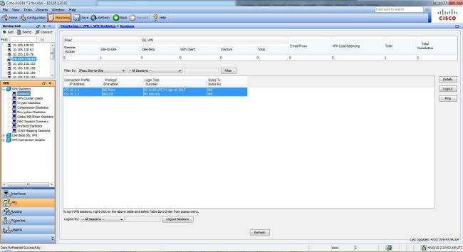
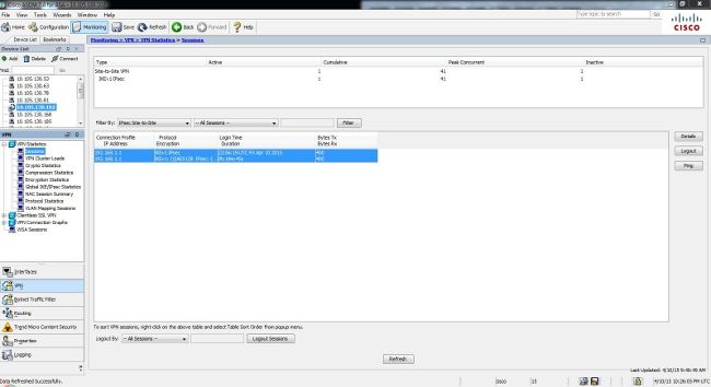
In order to view the tunnel status from the ASDM, navigate to Monitoring > VPN. This information is provided:
The peer IP address
The protocol that is used in order to build the tunnel
The encryption algorithm that is used
The time at which the tunnel came up and the up-time
The number of packets that are received and transferred
Tip: Click Refresh in order to view the latest values, as the data does not update in real-time.
This section describes how to verify your configuration via the CLI.
Phase 1
Enter this command into the CLI in order to verify the Phase 1 configuration on the Site B (5515) side:
Enter this command into the CLI in order to verify the Phase 1 configuration on the Site A (5510) side:
Phase 2
The show crypto ipsec sa command shows the IPsec SAs that are built between the peers. The encrypted tunnel is built between IP addresses 192.168.1.1 and 172.16.1.1 for the traffic that flows between the networks 10.1.1.0 and 10.2.2.0. You can see the two ESP SAs built for the inbound and outbound traffic. The Authentication Header (AH) is not used because there are no AH SAs.
Enter this command into the CLI in order to verify the Phase 2 configuration on the Site B (5515) side:
Enter this command into the CLI in order to verify the Phase 2 configuration on the Site A (5510) side:
Troubleshoot
Use the information that is provided in this section in order to troubleshoot configuration issues.
ASA Versions 8.4 and Later
Enter these debug commands in order to determine the location of the tunnel failure:
debug crypto ikev1 127 (Phase 1)
debug crypto ipsec 127 (Phase 2)
Here is a complete example debug output:
ASA Versions 8.3 and Earlier
Enter these debug commands in order to determine the location of the tunnel failure:
 >[оверквотинг удален]