WinToFlash для Windows
| Оценка: |
4.03 /5 голосов — 120 |
| Лицензия: | Бесплатная |
| Версия: | Lite 1.13.0000 | Сообщить о новой версии |
| Обновлено: | 07.11.2017 |
| ОС: | Windows 10, 8, 7, XP |
| Интерфейс: | Английский, Русский |
| Разработчик: | Novicorp |
| Категории: | Boot менеджеры — Образы дисков |
| Загрузок (сегодня/всего): | 103 / 378 291 | Статистика |
| Размер: | 9,13 Мб |
| СКАЧАТЬ | |
WinToFlash — отличное приложение для создания загрузочных USB-носителей для операционных систем семейства Windows. Обычно установочные пакеты с операционной системой хранятся на оптическом диске, что не всегда удобно и надежно. Во-первых, диск может повредиться, и даже незаметная царапина приведет к сбою установки. Во-вторых, современные ПК и ноутбуки все чаще выпускаются уже без оптических приводов, и хотя использование CD/DVD-дисков еще достаточно распространено, однако со временем их применение все уменьшается.
Именно в связи с выше сказанным и была разработана данная программа, с помощью которой Вы сможете полностью перенести программу установки ОС Windows на внешний Flash-накопитель за несколько простых действий. Программа имеет 2 основных режима работы: режим мастера и расширенный режим. Режим мастера идеален для новичков, т.к. тут все действия пользователя сводятся к простому пошаговому выбору конкретных параметров операционной системы и флеш-накопителя: доступна работа с ОС на диске в оптическом приводе или в виде образа на ПК, а также указываются все подключенные к ПК носители, которые могут использоваться в качестве загрузочных. Расширенный режим больше рассчитан на опытных пользователей, т.к. позволяет использовать дополнительные опции для тонкой настройки загрузочных характеристик, однако и здесь разобраться не составит большого труда.
Что стоит еще отметить, так это хороший для восприятия интерфейс приложения, который сразу интуитивно понятен, и портативность программы, что позволяет использовать ее без дополнительной установки в систему.
В целом, WinToFlash отличная программа, с которой Вам станет доступна установка Windows с Flash-карты, USB-носителя, HDD-диска да и вообще любого другого на Ваш выбор накопителя данных, что значительно надежней, чем хранение установочного пакета на простом оптическом диске.
- Перенос программы установки Windows XP/2003/Vista/2008/7/8 на USB накопитель.
- Полная поддержка редакций как 32-битной, так и 64-битной архитектуры.
- Полная поддержка форматов образов ISO, RAR, ARJ, ZIP, 7z, CAB, DMG.
- Перенос дисков восстановления или мини-ОС (BartPE на Windows) на USB-накопитель.
- Очистка USB-накопителя (форматирование FAT16 или FAT32).
- Перенос MS-DOS на USB-накопитель.
- Детальная настройка любых опций FAT для лучшей совместимости.
- Выбор загрузчика USB-накопителя — GRUB или Standard.
- Создание файла ответов для Windows Setup: добавьте серийный номер, имя пользователя и т.д.
- Детальная настройка процесса переноса Windows Setup.
- Проверка накопителя USB на предмет наличия ошибок файловой системы после переноса Windows Setup и многое-многое другое.
Repairing Lead Flashing – Mending Lead Rips and Tears and How to Use Flashing Tape
How to repair lead flashing. This project is about mending splits and tears in lead flashing and how to use lead flashing tape effectively. Also Understand why it is so important to repair your flashing.
Why Does Lead Flashing Need Repairing?
The main reason for repairing lead flahing, splits and cracks in lead and failure in lead flashing is because of its high coefficient of linear expansion. What on earth does that mean I hear you cry ! Simple. Lead expands a huge amount in the heat, shrinks a lot in the cold, and wanders about a bit at all temperatures in between.
If this expansion and contraction are allowed to continue freely, the lead flashing will last for 100 years. Lead flashings however are usually fixed in position for one reason or another and it is this limitation to movement that causes splits and cracks. Lead should also have support for every square mm of its coverage. If the lead is not fully supported it will eventually sag and split.
Although the image below is of a lead gutter (not lead flashing) this presents a good example of how lead can split when it sags. If the gutter is not supported correctly at regular intervals by supporting brackets then it will sag and weaken and then split.
Lead gutter full of sludge and debris
How To Repair Lead Flashing
When lead does split the correct way to repair it is to weld a piece of lead over the split. This is quite an advanced procedure which was always historically in the plumbers domain of jobs. Very few plumbers these days know how to weld lead and its very different to welding steel or ali. Welding lead uses a relatively cool flame and needs to be very precise.
Lead gutter full of sludge and debris
A DIY way to repair splits and cracks in lead and lead flashing is to use something we call Flash band (trade name) or sometimes it is also known as flashing tape.
Using Flashing Tape To Repair Lead Flashing
Flashing tape is comprised of a very thin strip of aluminium covered on one side by a tacky bitumen layer. It is self adhesive and can be used with a primer to help the adhesion but for lead repairs it works best when heated up. We must stress that this is not a permanent repair for lead as welding or replacement is the only permanent solution but in this, as in many other cases involving lead, it was cheaper for the customer to repair the lead every two years than it was to replace the lead gutters and flashing surrounding her property.
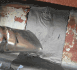
The gutter you can see above is lead lined. It looks a little orange in places because the wooden shingle roof had been sprayed a week before we arrived to repair the lead.
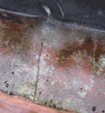
Firstly we traced the leak by looking for dripping below and then we cleaned out the gutter. It is important, both when welding lead or patching lead, that everything is spotlessly clean and degreased. We wiped the split, and either side of the split using paper towels to make sure we soaked up most of the moisture which had filtered through the split and was puddling under the lead.
Cleaning the split lead thoroughly
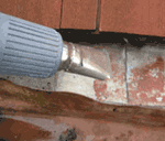
Next, using a hot air gun we heated the area gently for about half an hour. This will warm the lead which in turn will warm the water under the lead which will evaporate out through the split. In all cases you must try to get all the water out from under the lead because, if it is left there and the split sealed, the water can go no where and it will eventually rot the timber it is sitting on.
Heat the area to evaporate any remaining trace of water
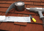
Tools and materials required for this job are minimal and all can be bought in our tool store. A roll of flashing tape is required, as is a heavy duty hobby knife. A good hot air gun is useful although a standard blowlamp can be used. For the novice DIY enthusiast we would suggest the hot air gun rather than the blowlamp as it is a lot less dangerous. Rags and perhaps a roll of heavy duty kitchen towel are also needed. Gloves are also a good idea!
Selection of tools required for lead repair
Once again, we must stress that this is only a temporary repair. If done properly it will last 2 or even 3 years but as the lead continues expanding and contracting with the varying temperatures in this country, it is inevitable that the patch will split also. The tape, of course, is fixed on both sides of the split so cannot expand and contract well. This means that it may not move at the same time and over the same distance as the lead.
Cut a length of flashing tape ready. After heating the area and allowing the water to evaporate the lead should stay warm for a few minutes. This time should be spent warming the bitumen base on the flashing until it is warm and soft but not runny.
Heat the lead flashing
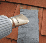
Quickly warm the lead again and lay the flashing tape over the split. Use a rag (you should also be wearing gloves) to press the flashing tape into place. Warm the top of the tape after a few seconds to keep the bitumen nice and warm. It sticks so much better this way.
Heating top of patch
Finally give a final press down onto the patch using a cloth. Start as you do with wall paper, from the centre, pushing towards the edges to get rid of any air trapped under the patch.
Press down using a rag or towel
Repairing lead flashing and splits and cracks in lead using this method should provide a good temporary fix and from start to finish, even with cleaning out the gutter, took 1½ hours.
You might want to go to our video section on roofing and watch a film on installing flashings for a visual demonstration on how to go about this fiddly job.
All project content written and produced by Mike Edwards , founder of DIY Doctor and industry expert in building technology.
Lead flashing to windows
Some newer boards with full USB support must be flashed in USB DFU mode. This is a straightforward process in Configurator versions 0.67 and newer. The standard flashing procedure should work successfully with the caveat of some platform specific problems as noted below. The «No reboot sequence» checkbox has no effect as the device will automatically be detected when already in bootloader mode (a DFU device will appear in the connect dropdown if this is the case). The Full chip erase checkbox operates as normal. The baudrate checkbox is ignored as it has no relevance to USB.
If you see no signs of life on your host computer when you plug in your board, check your cable with your mobile phone or some other USB device — some charging cables have only the power pins connected. These will power up the board, so the leds light up, but the host computer will not react to the device at all. You need a proper USB cable to connect your board to the Cleanflight Configurator.
Platform Specific: Linux
Linux requires udev rules to allow write access to USB devices for users. An example shell command to achieve this on Ubuntu is shown here:
This assigns the device to the plugdev group (a standard group in Ubuntu). To check that your account is in the plugdev group type groups in the shell and ensure plugdev is listed. If not you can add yourself as shown (replacing with your username):
If you see your ttyUSB device disappear right after the board is connected, chances are that the ModemManager service (that handles network connectivity for you) thinks it is a GSM modem. If this happens, you can issue the following command to disable the service:
If your system lacks the systemctl command, use any equivalent command that works on your system to disable services. You can likely add your device ID to a blacklist configuration file to stop ModemManager from touching the device, if you need it for cellural networking, but that is beyond the scope of cleanflight documentation.
Platform Specific: Windows
Chrome can have problems accessing USB devices on Windows. A driver should be automatically installed by Windows for the ST Device in DFU Mode but this doesn’t always allow access for Chrome. The solution is to replace the ST driver with a libusb driver. The easiest way to do that is to download Zadig. With the board connected and in bootloader mode (reset it by sending the character R via serial, or simply attempt to flash it with the correct serial port selected in Configurator):
- Open Zadig
- Choose Options > List All Devices
- Select STM32 BOOTLOADER in the device list
- Choose WinUSB (v6.x.x.x) in the right hand box
- Click Replace Driver
- Restart Chrome (make sure it is completely closed, logout and login if unsure)
- Now the DFU device should be seen by Configurator
Bricking your device
If you ever manage to brick your FC, that means, to put a firmware on it that does not work, the Cleanflight Configurator is not able to talk to it, and might not be able to reset it into DFU (Device Firmware Update, means: flashing) mode in order to overwrite the broken firmware with a good one.
This is where the «boot» pins on your FC come into play. If the two boot pins (might be named differently on your FC board) are connected with each other when the FC is powered up (in our case: connected to USB), the FC board will automatically start up in DFU (flashing) mode and identify itself not as a ACM or USB device (offering a serial interface) but as a DFU mode device.
There is a special switch in the Cleanflight Configurator program ‘No reboot sequence’. You should activate this if you power up your FC with boot pins connected to each other. What the switch does, is to avoid sending commands to the FC that should put the FC into DFU mode, and rather assume that the FC is already in DFU mode.
Why do we care about not sending useless commands that try to achieve something that has already been achieved? The reason is that if you send this commands while already in DFU mode, there is a slight chance that the commands contain something that makes sense to the DFU mode command interpreter; if that happens, it might enter a state where flashing is no longer possible and hence, your system remains bricked.
Troubleshooting, and some background (Linux)
Sometimes, connecting the Configurator program to the FC, or flashing the FC using the configurator, fail. The following section provides some background that help to identify the reason of the problem.
First, when connecting your FC to the computer, the LED on the board should light up — if they dont, your cable, your FC board, or your computer USB port are broken. If they do, wait a few seconds, then check whether your Linux and your board have properly established a connection. You do this with the lsusb command which will list all USB devices that are currently connected. In the example below, the FC was found as Device 025 on Bus 001. With lsusb -vs bus:device , detailed information about the device can be queried:
If your FC-device is not listed, Linux has not managed to connect to it. This might be a driver issue. For example, some FCs use a CP2102 chip that translates USB protocol to serial. On the USB side (on your Linux computer), a special driver is needed that knows how to speak with a CP2102 chip. This driver is a file «cp210x.ko» . If you have this driver available, but it is not active, you can install it into your system (and then, check whether it was installed) with
If lsmod shows the cp210x line, your system has successfully installed the driver. If you do not have the driver on your system, you can download it from https://www.silabs.com/products/development-tools/software/usb-to-uart-bridge-vcp-drivers . Unpack the zip-File and follow the instructions (October 2017, the correct version was called 3.x.x/4.x.x and the instructions were in ‘CP210x_VCP_Linux_3.13.x_Release_Notes.txt’ which becomes visible only after unzipping).
Note that for devices that use the CP2102 chip, the FC might not show under its real name, but instead the CP2102 bridge chip is reported as USB device by your computer. For example, with a NAZE — which has a CP2102 — the lsusb command will give you
After you checked that your Linux has hooked on with your FC, it is instructive to check the messages in the kernel message ring buffer. Here are the messages that are generated after first a NAZE is connected and disconnected again, then a SPRACINGF3EVO is connected, then the Cleanflight configurator is used to flash a new firmware on the SPRACINGF3EVO, and finally the SPRACINGF3EVO is disconnected. The command to read the kernel message ring buffer is dmesg :
From this log file, you can see that the NAZE is resulting in a device called «ttyUSB0» and the SPRACINGF3EVO results in a device «ttyACM0».
Sometimes, however, you get a problem and the freshly created device «ttyACMx» or «ttyUSBy» will be destroyed immediately after creation. This may look like this:
Should you encounter this problem, it is probably the modem manager service that prevents Ubuntu from creating the device. Try killing it, and if that works, you might want to prevent it from restarting at the next reboot (here: for Ubuntu):
Now, you have a device, e.g. «ttyACM0» or «ttyUSB0». This device is found in the Linux file system at /dev/ttyACM0 or /dev/ttyUSB0. Have a look:
The device is owned by user root, group root, and only people in the group «root» are allowed to use it. This is a problem (which is mentioned above already) — unless you are root, you can not write to your FC, so the Cleanflight configurator will fail. It is possible to fix this issue by «chgrp» and «chmod» commands directly on the file /dev/ttyACM0. However, since USB devices are created on-the-fly when connection to the USB port happens, such a ‘chmod’ would have to be repeated every time when you plug in your board or after you switch off your computer.
In order to have something that springs automatically into action every time a new USB device is connected, you can create a so-called udev rule. Every time a new device is activated in the kernel — i.e. if you plug in your FC board via USB — the kernel checks all the udev rules (in Ubuntu, they are in /etc/udev/rules.d/). If one of them applies to the new device, it is used. udev rules can — among other things — change the ownership, the group ownership, and the permissions of the new USB device file. So, a udev rule can be used to grant full access to the new USB device to everyone in a Unix group.
The rule needs to be smart — we do not want to have it applied to every USB device that is connected to the PC, like your USB stick or your mouse. It should only be applied to your FC. Luckily, this is possible, because USB devices tell the host computer a lot about themselves — they present things like their manufacturer and their product ID. So, the udev rule should apply only to Flight Controllers.
ST Microelectronics, the manufacturer of the microcontroller on your FC, has the (internationally standardized) USB Vendor ID ‘0483’.
A udev rule which will put all STM microcontrollers into group «plugdev» can be established e.g. by
(if you have no luck with it, try the more generic KERNEL==»ttyACM3″, GROUP=»plugdev» which sets any new USB device that is a ttyACM to group plugdev without checking whether it is a STM microcontroller). Note you might need to reboot your system for the rule to take effect. Usually though, a reboot is not needed, stopping the udev system service and restarting it has the same effect:
Connect your FC to USB, and then check the permissions of the resulting device file (e.g. /dev/ttyACM0). If the udev rule is set up properly, this device file should be group «plugdev» with group permissions «rw». Of course, you must be member of group «plugdev» to take advantage of it.
When looking into the output of ‘dmesg’ above, you will have noticed that when the Cleanflight Configurator program was flashing the firmware, the USB device ‘STM32 virtual COM port’ disappeared (device 18), and instead, a new device appeared — the device 19, «STM Bootloader». We can see that it has the idVendor 0483 and the idProduct df11. Every STM32 microcontroller has a special bootloader mode (the famous ‘unbrickable bootloader’, called DFU mode for Device Firmware Update) that identifies itself with a product ID of ‘df11’.
So, Cleanflight Configurator has made the FC to unplug itself (virtually) from your PC and to reconnect again as a different device!
Since your FC can function — and present itself to a USB host — as two different devices — a DFU bootloader device, which has commands to flash a firmware, and a serial interface, which can be used to speak the MultiWii protocol and talk to the Cleanflight Configurator (configuration section) — there might be two different Linux devices /dev/ttyXXX and /dev/ttyYYY corresponding to the two modes of your FC.
Therefore, it is entirely possible to have read-write permissions of one of the two devices set up properly, but not for the other. This will lead to the situation that you can either flash your device, but not configure it in the Configurator, or configure it, but not flash it. Therefore, you should have two udev rules in place — one for the serial device for configuring, one for the DFU mode device for flashing.

