brief tutorial on CRC computation
A CRC is a long-division remainder. You add the CRC to the message, and the whole thing (message+CRC) is a multiple of the given CRC polynomial. To check the CRC, you can either check that the CRC matches the recomputed value, or you can check that the remainder computed on the message+CRC is 0. This latter approach is used by a lot of hardware implementations, and is why so many protocols put the end-of-frame flag after the CRC.
It’s actually the same long division you learned in school, except that:
We’re working in binary, so the digits are only 0 and 1, and
When dividing polynomials, there are no carries. Rather than add and subtract, we just xor. Thus, we tend to get a bit sloppy about the difference between adding and subtracting.
Like all division, the remainder is always smaller than the divisor. To produce a 32-bit CRC, the divisor is actually a 33-bit CRC polynomial. Since it’s 33 bits long, bit 32 is always going to be set, so usually the CRC is written in hex with the most significant bit omitted. (If you’re familiar with the IEEE 754 floating-point format, it’s the same idea.)
Note that a CRC is computed over a string of bits, so you have to decide on the endianness of the bits within each byte. To get the best error-detecting properties, this should correspond to the order they’re actually sent. For example, standard RS-232 serial is little-endian; the most significant bit (sometimes used for parity) is sent last. And when appending a CRC word to a message, you should do it in the right order, matching the endianness.
Just like with ordinary division, you proceed one digit (bit) at a time. Each step of the division you take one more digit (bit) of the dividend and append it to the current remainder. Then you figure out the appropriate multiple of the divisor to subtract to being the remainder back into range. In binary, this is easy — it has to be either 0 or 1, and to make the XOR cancel, it’s just a copy of bit 32 of the remainder.
When computing a CRC, we don’t care about the quotient, so we can throw the quotient bit away, but subtract the appropriate multiple of the polynomial from the remainder and we’re back to where we started, ready to process the next bit.
A big-endian CRC written this way would be coded like:
Notice how, to get at bit 32 of the shifted remainder, we look at bit 31 of the remainder before shifting it.
But also notice how the next_input_bit() bits we’re shifting into the remainder don’t actually affect any decision-making until 32 bits later. Thus, the first 32 cycles of this are pretty boring. Also, to add the CRC to a message, we need a 32-bit-long hole for it at the end, so we have to add 32 extra cycles shifting in zeros at the end of every message.
These details lead to a standard trick: rearrange merging in the next_input_bit() until the moment it’s needed. Then the first 32 cycles can be precomputed, and merging in the final 32 zero bits to make room for the CRC can be skipped entirely. This changes the code to:
With this optimization, the little-endian code is particularly simple:
The most significant coefficient of the remainder polynomial is stored in the least significant bit of the binary “remainder” variable. The other details of endianness have been hidden in CRCPOLY (which must be bit-reversed) and next_input_bit().
As long as next_input_bit is returning the bits in a sensible order, we don’t have to wait until the last possible moment to merge in additional bits. We can do it 8 bits at a time rather than 1 bit at a time:
Or in little-endian:
If the input is a multiple of 32 bits, you can even XOR in a 32-bit word at a time and increase the inner loop count to 32.
You can also mix and match the two loop styles, for example doing the bulk of a message byte-at-a-time and adding bit-at-a-time processing for any fractional bytes at the end.
To reduce the number of conditional branches, software commonly uses the byte-at-a-time table method, popularized by Dilip V. Sarwate, “Computation of Cyclic Redundancy Checks via Table Look-Up”, Comm. ACM v.31 no.8 (August 1998) p. 1008-1013.
Here, rather than just shifting one bit of the remainder to decide in the correct multiple to subtract, we can shift a byte at a time. This produces a 40-bit (rather than a 33-bit) intermediate remainder, and the correct multiple of the polynomial to subtract is found using a 256-entry lookup table indexed by the high 8 bits.
(The table entries are simply the CRC-32 of the given one-byte messages.)
When space is more constrained, smaller tables can be used, e.g. two 4-bit shifts followed by a lookup in a 16-entry table.
It is not practical to process much more than 8 bits at a time using this technique, because tables larger than 256 entries use too much memory and, more importantly, too much of the L1 cache.
To get higher software performance, a “slicing” technique can be used. See “High Octane CRC Generation with the Intel Slicing-by-8 Algorithm”, ftp://download.intel.com/technology/comms/perfnet/download/slicing-by-8.pdf
This does not change the number of table lookups, but does increase the parallelism. With the classic Sarwate algorithm, each table lookup must be completed before the index of the next can be computed.
A “slicing by 2” technique would shift the remainder 16 bits at a time, producing a 48-bit intermediate remainder. Rather than doing a single lookup in a 65536-entry table, the two high bytes are looked up in two different 256-entry tables. Each contains the remainder required to cancel out the corresponding byte. The tables are different because the polynomials to cancel are different. One has non-zero coefficients from x^32 to x^39, while the other goes from x^40 to x^47.
Since modern processors can handle many parallel memory operations, this takes barely longer than a single table look-up and thus performs almost twice as fast as the basic Sarwate algorithm.
This can be extended to “slicing by 4” using 4 256-entry tables. Each step, 32 bits of data is fetched, XORed with the CRC, and the result broken into bytes and looked up in the tables. Because the 32-bit shift leaves the low-order bits of the intermediate remainder zero, the final CRC is simply the XOR of the 4 table look-ups.
But this still enforces sequential execution: a second group of table look-ups cannot begin until the previous groups 4 table look-ups have all been completed. Thus, the processor’s load/store unit is sometimes idle.
To make maximum use of the processor, “slicing by 8” performs 8 look-ups in parallel. Each step, the 32-bit CRC is shifted 64 bits and XORed with 64 bits of input data. What is important to note is that 4 of those 8 bytes are simply copies of the input data; they do not depend on the previous CRC at all. Thus, those 4 table look-ups may commence immediately, without waiting for the previous loop iteration.
By always having 4 loads in flight, a modern superscalar processor can be kept busy and make full use of its L1 cache.
Two more details about CRC implementation in the real world:
Normally, appending zero bits to a message which is already a multiple of a polynomial produces a larger multiple of that polynomial. Thus, a basic CRC will not detect appended zero bits (or bytes). To enable a CRC to detect this condition, it’s common to invert the CRC before appending it. This makes the remainder of the message+crc come out not as zero, but some fixed non-zero value. (The CRC of the inversion pattern, 0xffffffff.)
The same problem applies to zero bits prepended to the message, and a similar solution is used. Instead of starting the CRC computation with a remainder of 0, an initial remainder of all ones is used. As long as you start the same way on decoding, it doesn’t make a difference.
© Copyright The kernel development community.
Источник
Как я реанимировал устройство (JTAG-эмулятор BH-USB-560v2) через U-Boot
У меня есть сомнения, что JTAG-эмулятор для отладки процессоров фирмы Texas Instruments — настолько распространённое устройство, чтобы его реанимация была бы кому-то интересна. Однако статья может быть полезна тем, кто пытается реанимировать что-нибудь на базе одноплатника с Linux, имея ограниченные ресурсы и информацию. Можно рассматривать это как некоторый практикум работы с U-Boot.

Вместо предисловия
Тот, кто занимался отладкой программ для встраиваемых систем, знает, что для подключения к процессорам нужно использовать специальные устройства. Для семейства процессоров фирмы Texas Instruments используются адаптеры, называемые JTAG-эмуляторами.
Их существует множество, и от разных производителей. В моём парке помимо прочих значится Blackhawk USB560v2. Надо признаться, не самая дешёвая железка. И вот однажды она перестала работать без видимых на то причин.
Симптомы
Всё произошло в один прекрасный день, девайс просто перестал загружаться и определяться по USB. Моргал светодиод, но в состояние «готово к использованию» не переходил.
У этого устройства есть занятный документированный режим: после 10-15 неудачных загрузок оно должно было перейти в специальный режим (safe mode), который позволил бы его перепрошить. Однако моё устройство в этот режим переходить отказывалось, до этапа USB нумерации не доходило, и поэтому возможности перепрошить штатной утилитой не было. Переписка со службой поддержки ни к чему не привела: по технике помогать они мне отказались, предложив лишь отправить (за свой счёт) девайс им в США на диагностику и ремонт.
Ничего не оставалось, как приступить к самостоятельной починке.
На хосте установлен Ubuntu, некоторые использованные утилиты входят в дистрибутив, некоторые устанавливаются через apt.
Внешний осмотр
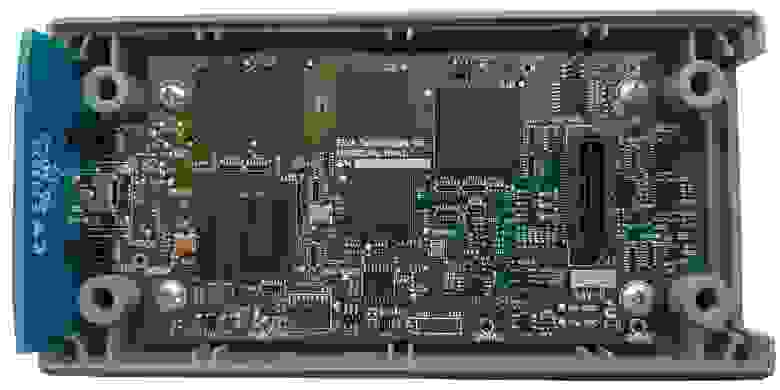
Разбираем, смотрим на плату. На плате расположены:
Особенно порадовал заботливо офомленный разъём UART, который мало того, что был разведён под стандартную гребёнку 2.54 мм, так ещё и контакты были подписаны. Такого я не встречал уже давно, максимум пятачки на плате, да ещё и с ничего не значащими маркировками типа TP1 и т.п.
Приступим
Подключаем USB-UART (не забываем про уровень, он здесь 3.3 В). Запускаем minicom, получаем:
Как видим, последовательность вполне стандартная: сначала грузится bootloader (TI UBL), затем U-Boot, который в свою очередь грузит ядро Linux.
По логу очевидно, что что-то слетело во внутренней NAND Flash, при загрузке ядра Linux не сходится контрольная сумма. Однако можно прервать загрузку и войти в консоль U-Boot.
Ознакомимся с доступными командами:
Посмотрим переменные окружения:
Первым делом я попытался отключить проверку и загрузиться с помощью команд U-Boot.
Продвинулся чуть дальше, но не намного:
Дальше устройство виснет.
Из переменных окружения видно, что образ ядра лежит в NAND Flash со смещением 0x60000, при загрузке копируется по адресу 0x80700000 (согласно memory map процессора это адресное пространство внешней памяти DRAM) и загружается. Размер образа ядра, как видно из лога, составляет 1236292 байт. Я попробовал проделать это вручную. Предполагаем, что образ хранится в формате uImage, поэтому накидываем 64 байта на заголовок, получаем 1236356 байт = 0x12DD84:
Дальше мне захотелось выкачать дамп образа на компьютер, чтобы поиграться с ним. Я не придумал ничего лучше, как записать лог консоли с выводом памяти на экран, а затем преобразовать его в бинарный файл.
Запускаем minicom с записью лога:
Выводим содержимое памяти на экран:
Выходим из minicom, редактируем лог, убрав лишние строчки, преобразуем в бинарник:
Мне захотелось перепаковать образ, чтобы он не выдавал ошибки контрольной суммы. Удаляем первые 64 байта, а затем делаем новый uImage:
Заливаем полученный файл обратно по протоколу YModem:
Пробуем загрузиться, но также виснем на этапе распаковки ядра:
Вполне ожидаемо, на что тут можно было надеяться. Но хотя бы прокачали воркфлоу обмена файлами, уже неплохо.
Всё, что у нас есть, это файл прошивки с сайта производителя, USB560v2_firmware_5.0.573.0.bin . Я предполагал, что в этом файле содержится образ ядра, но разумно было бы ожидать, что файл зашифрован хотя бы простеньким ключом. Поэтому, признаюсь, я сорвался и написал производителю просьбу предоставить мне небитый uImage с тем, чтобы я его залил в устройство и загрузился с него, а потом уже смог бы перепрошить устройство штатной утилитой по USB. Даже сослался на условия GPL (под которой распространяется Linux), по которым им не мешало бы в дополнение предоставить и исходные коды ядра.
Сразу после отправки запроса я решил всё же попробовать распаковать файл прошивки, как простой архив. И, о чудо, получилось!
После распаковки появилось два файла: uImage и rootfs.tar.gz . То, что доктор прописал, образ ядра и корневая файловая система.
Осталось залить uImage в память устройства по YModem и запуститься, что я и сделал. Устройство успешно загрузилось в тот самый safe mode, я дал отбой тех. поддержке производителя и, думая, что прошью устройство в следующий раз, спокойно отправился спать.
Вторая серия
Однако на следующий день меня ждал неприятный сюрприз. Устройство перестало успешно загружаться. Что я только не перепробовал, получал ошибку:
Я сделал вывод, что корневая файловая система так же повредилась. Что ж, значит надо прошить и её.
Для начала запишем uImage в NAND, чтобы не грузить какждый раз через UART (надо признаться, на скорости 115200 файл даже размером в один мегабайт грузится ощутимое время). При работе с NAND на всякий случай выравниваем размер образа до размера страницы NAND в большую сторону (где-то встречал такую рекомендацию), а размер страницы у нас составляет 1024 байта = 0x800 (см. самый первый лог).
Из лога загрузки ядра выделяем полезную информацию:
Значит корневую файловую систему надо записать в NAND со смещением 0x260000. Осталось только понять, в каком формате. Вспоминаем про переменные окружения U-Boot, в частности про вот эту строчку:
Значит, нам надо преобразовать наш rootfs.tar.gz , выуженный из файла прошивки, в формат JFFS2. По подсказке с Wiki от Texas Instruments делаем это ( sudo нужен для tar , так без него выдаёт ошибки при запуске команды mknod ):
Загружаем полученный файл в память устройства, а затем копируем в нужный участок NAND (размер также округляем до страницы):
Скрещиваем пальцы, перезагружаемся, ну теперь уж всё точно хорошо.
Послесловие
Да, итоговая процедура получилась не очень-то сложной, настоящего реверс-инжиниринга здесь в сущности немного. Но я лично для себя узнал немало нового о низкоуровневых вещах в процессе загрузки встраиваемого Linux, научился работать с консолью U-Boot.
Видно, что защитой ребята особо не заморачивались. После загрузки Linux в консоли появляется предложение залогиниться. Логин root без пароля позволяет зайти с административным доступом и делать с устройством всё что угодно. Самое интересное содержится в директории /usr/local/bin .
Источник


