5.1 Драйвер последовательного порта в Linux
Драйвер последовательного порта в Linux тесно связан с подсистемой TTY. Уровень TTY является отдельным классом символьного устройства. На встраиваемых системах, имеющих последовательный порт, уровень TTY используется для предоставления доступа к низкоуровневому последовательному порту. Часто встраиваемая плата может иметь больше, чем один последовательный порт; обычно другие порты могут использоваться для коммутируемого доступа с использованием таких протоколов, как PPP или SLIP. Часто задаётся вопрос, должны ли в таком случае быть предоставлены разные драйверы последовательных портов. Ответ: нет, так как TTY отделяет драйвер последовательного порта от приложения, так что может быть предоставлен один драйвер последовательного порта, вне зависимости от того, как он используется.
Пользовательский процесс не общается с драйвером последовательного порта напрямую. TTY представляет собой стек программного обеспечения над драйвером и экспортирует всю функциональность через устройства TTY. Подсистема TTY разделяется на три слоя, как показано на Рисунке 5.2. Как показывает Рисунок 5.2, каждое устройство, взаимодействующее с подсистемой TTY, связано с дисциплиной линии, которая решает, как передаваемые или принимаемые данные обрабатываются низкоуровневым драйвером. Linux предлагает дисциплину линии по умолчанию N_TTY, которая может быть использована для того, чтобы использовать в качестве стандартного терминала последовательный порт. Но дисциплины линий также могут использоваться для реализации более сложных протоколов, таких как X.25 или протокол PPP/SLIP.
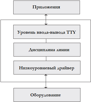
Рисунок 5.2 Подсистема TTY.
В Linux пользовательские процессы обычно имеют управляющий терминал. Управляющий терминал это то, где процесс принимает ввод, и то, где осуществляет стандартный вывод и куда перенаправляются ошибки. TTY и управление процессами автоматически заботятся о назначении и управлении управляющими терминалами. (* Процессы могут предпочесть работать без управляющего терминала. Такие процессы называются службами (daemon, демонами). Службы используются для запуска задач в фоновом режиме после отключения от управляющего терминала, чтобы они не пострадали, когда терминал закрывается.)
Существует ещё один набор устройств TTY, которые используются во встраиваемых системах. Это виртуальные или псевдо-TTY устройства (PTY). PTY являются мощным средством межпроцессного взаимодействия. Процессы, использующие псевдо-TTY получают все преимущества межпроцессного взаимодействия и подсистемы TTY. Например, подсистема Telnet на Linux использует псевдо-терминал для связи между telnetd (главной службой Telnet) и процессом, который является порождением telnetd . По умолчанию количество псевдо-терминалов TTY установлено в 256; оно может быть изменено на меньшее число из-за его ограниченного использования во встраиваемых системах.
Теперь обсудим реализацию в Linux драйвера последовательного порта. В ядре версии 2.4 структурой данных, используемой для подключения последовательного драйвера к подсистеме TTY, является tty_driver . Драйвер последовательного порта заполняет эту структуру такой информацией, как название устройства, старший/младший номера и всеми необходимыми интерфейсами, требуемыми вводом-выводом TTY и уровнем дисциплины линии для обращения к драйверу последовательного порта. В версии 2.4 функции, экспортируемые в уровень TTY от драйвера последовательного порта, содержит файл drivers/char/generic_serial.c ; он может быть использован для подключения к уровню TTY вашего низкоуровневого драйвера последовательного порта.
В ядре версии 2.6 уровень драйвера последовательного порта был очищен, так что перенос нового драйвера последовательного порта в Linux становится проще. Драйвер последовательного порта больше не должен беспокоиться о вызовах TTY; вернее, это выполняет уровень абстракции. Это делает работу по написанию драйвера последовательного порта легче. Этот раздел объясняет, как на новой платформе может быть написан драйвер последовательного порта.
Путь есть вымышленное оборудование UART MY_UART со следующими функциональными возможностями:
▪ Простая логика передачи и приёма; один регистр для передачи данных и один регистр для получения данных
▪ Допустимые настройки скорости 9600 или 19200 бод
▪ Для оповещения о конце передачи или приёма данных используется прерывание
▪ Оборудование имеет только один порт UART (то есть, оно однопортовое)
Мы предполагаем, что макрос, показанный в Распечатке 5.1, уже доступен для доступа к оборудованию. Также эти макросы предполагают, что регистры и буферы отображаются начиная с базового адреса MY_UART_BASE . Мы также предполагаем, что BSP для этой конкретной платы уже сделал это отображение, так что мы можем начать эффективно использовать адрес MY_UART_BASE . Тем не менее, мы не обсуждаем поддержку драйвером модема; это выходит за рамки данного раздела.
Сначала мы обсудим конфигурацию устройства. В файл drivers/serial/Kconfig добавляем следующие строки:
Test UART driver
Затем в drivers/serial/Makefile добавляем следующую строку:
Опция конфигурации выбирает, чтобы файл my_uart.c был скомпилирован вместе с drivers/serial/serial_core.c . Файл serial_core.c содержит общие процедуры UART, которые взаимодействуют с TTY и модулями дисциплины линии. В дальнейшем универсальный уровень UART, реализованный в serial_core.c , упоминается как ядро UART .
Источник
Linux uart device driver
This article is based on the mini2440 development board Linux version number is linux-2.6.32.2 study notes
1. Basic information of uart
- S3C2440A provides 3 independent serial ports.
- The operation of the serial port uses interrupt or DMA mode.
- The receiving and sending buffer of the serial port is 64-byte.
2. uart hardware initialization
- The function called by uart initialization is: s3c24xx_init_uarts, this function is called by mini2440_map_io, and the mini2440_map_io function is assigned to the machine_desc.map_io function. The machine_desc.map_io function is called inside the start_kernel function.
- The s3c24xx_init_uarts function transfer parameters (mini2440_uartcfgs, 3), as shown below:
.hwport is the hardware port number, and other structure members will look back temporarily.
- The s3c24xx_init_uarts function calls the cpu->init_uarts function.
The final call is the s3c244x_init_uarts function.
- s3c244x_init_uarts function, passed the parameter s3c2410_uart_resources
s3c24xx_init_uartdevs function analysis
Fill platdev with name, resource, num_resources, dev.platform_data and other structure members, and then assign platdev to the s3c24xx_uart_devs global variable. The final result is as follows:
Three. uart device registration
From the previous step, the uart device is s3c24xx_uart_devs, and the number of devices is 3.
Where is the uart device registered? You can see that the uart device is registered in the s3c_arch_init function.
When is the s3c_arch_init function called? Through arch_initcall(s3c_arch_init), the s3c_arch_init function is called when the kernel is started.
pdev->id = 0,1,2, the final registered device is s3c2440-uart.0, s3c2440-uart.1, s3c2440-uart.2
Device path: /sys/devices/platform/s3c2440-uart.0
/sys/devices/platform/s3c2440-uart.1
/sys/devices/platform/s3c2440-uart.2
4. Registration of uart driver
Search for the device name s3c2440-uart and find the uart driver registration file /drivers/serial/s3c2440.c file
The definition of platform_driver in the s3c2440.c file is as follows:
Finally, register the uart driver by calling the platform_driver_register function.
- The driver is in the /sys/bus/platform/drivers/s3c2440-uart directory.
5. Probe function of uart driver
The probe function of the uart driver is s3c2440_serial_probe, but the s3c2440_serial_probe function calls the s3c24xx_serial_probe function, and the s3c24xx_serial_probe function passes the parameter s3c2440_uart_inf, as shown below:
.fifosize = 64: indicates that the buffer is 64 bytes.
.rx_fifomask = 63: The read buffer buffer count is normally 0
63, otherwise the read buffer buffer is full.
.rx_fifoshift = 0: Because Rx FIFO Count is [5:0], no need to move
rx_fifofull = (1 divisor = 1, if it is FCLK/n clock, clk->divisor needs to be obtained according to [15:12] of UCON register. 
Now look at the s3c24xx_serial_probe function.
- Port initialization, the port is the global variable s3c24xx_serial_ports. Call the function s3c24xx_serial_init_port. There is a uart_port type variable in the s3c24xx_serial_ports variable, which is mainly used to assign a value to the variable.
①Save the info structure
②ourport->port.fifosize = info->fifosize = 64, the default value given before is 16
③ Get mem resources and save them in port->mapbase and port->membase variables
④Get the terminal number and save it in ourport->rx_irq and ourport->tx_irq variables
⑤Get uart clock and save it in ourport->clk
⑥Reset fifo, set the serial port, call the function s3c24xx_serial_resetport, actually call the reset_port function of s3c2440_uart_inf.
is the s3c2440_serial_resetport function. The s3c2440_serial_resetport function sets the registers of the following steps.
⑦Add 0x3c5 (1111000101) to UCON0 register
1: Level interrupt (not pulse interrupt) is generated when sending
1: Generate a level interrupt when receiving
1: Allow timeout interrupt when receiving
1: Enable error interrupt when receiving
0: Normal mode, no loopback mode, just a serial port RX connected to TX
0: Do not send break signal
01: Send data in interrupt or polling mode
01: Receive data in interrupt or polling mode
⑧ Write 0x03 (00000011) to ULCON0 register
0: Normal mode (not infrared mode)
000: No check digit
0: 1 stop bit
11: 8 data bits 
⑨ Write 0x51 (1010001) to the UFCON0 register
01: Tx FIFO Trigger Level = 16-byte
01: Rx FIFO Trigger Level = 8-byte
0:Reserved
0:
0:
1: Enable FIFO 
- Call uart_add_one_port function, uart_add_one_port function is mainly to register tty device.
The registered device is s3c2410_serial0, under the directory: /sys/devices/platform/s3c2440-uart.0/tty.
6. ktermios structure
The ktermios structure structure is defined as follows:
Refer to Daniel’s blog below
c_iflag is commonly used as follows:
IGNBRK: Ignore the BREAK status in the input
BRKINT
IGNPAR: Ignore frame errors and parity errors
PARMRK: If IGNPAR is not set, insert /377 /0 before the character with parity error or frame error. If neither IGNPAR nor PARKRK is set, characters with parity errors or frame errors are regarded as /0
INPCK: Enable input parity detection
ISTRIP: remove the eighth digit
INLCR: Translate NL in input into CR
IGNCR: Ignore the carriage return in the input
ICRNL: Translate the carriage return in the input to a new line (unless IGNCR is set)
IUCLC: Map uppercase letters in the input to lowercase letters
IXON: Enable input XON flow control
IXANY: Allow any character to restart output
IXOFF: Enable input XFF flow control
C_oflag is commonly used as follows:
OPOST: Enable specific implementation of self-defined output processing.
OLCUC: Map lowercase letters in the output to uppercase letters.
ONLCR: Map the newline character in the output to carriage return-line feed.
OCRNL: Map the carriage return in the output to a newline character
ONOCR: Do not output carriage return in column 0.
ONLRET: Do not output carriage return.
OFILL: Send filling characters as a delay, instead of using timing to delay.
OFDEL: The filling character is ASCII DEL (0177). If not set, the fill character is ASCII NUL.
NLDLY: New line delay mask. The values are NL0 and NL1.
CRDLY: Carriage return delay mask. The value is CR0, CR1, CR2, or CR3.
TABDLY: Horizontal tab delay mask. The value is TAB0, TAB1, TAB2, TAB3 (or XTABS). The value is TAB3, which is XTABS, which will expand tabs into spaces (each tab is filled with 8 spaces).
BSDLY: Back-off delay mask. The value is BS0 or BS1. (Never been realized)
VTDLY: Vertical tab delay mask. The value is VT0 or VT1.
FFDLY: Entry delay mask. The value is FF0 or FF1.
c_cflag flag constant:
CBAUD: Baud rate mask (4+1 bits).
CBAUDEX: Extended baud rate mask (1 bit), included in CBAUD.
CSIZE: Character length mask. The value is CS5, CS6, CS7, or CS8.
CSTOPB: Set two stop bits instead of one.
CREAD: Open the recipient.
PARENB: Allow output to generate parity information and input parity.
PARODD: Input and output are odd parity.
HUPCL: After closing the device in the last process, lower the modem control line (hang up).
CLOCAL: Ignore the modem control line.
LOBLK: Block output from the non-current shell layer (used for shl). (?)
CIBAUD: Input speed mask. The values of the CIBAUD bits are the same as the CBAUD bits, with the IBSHIFT bit shifted to the left.
CRTSCTS: Enable RTS/CTS (hardware) flow control.
Seven. uart_ops structure
In the above probe function, there is an important structure uart_ops, which defines the operation of the uart driver layer.
Let’s analyze the functions inside one by one.
- s3c24xx_serial_tx_empty function analysis
This function is to determine whether the sender is empty
① Read the UFCON0 register to determine whether the 0th bit is 1, 1 means FIFO mode, 0 means non-FIFO mode
② In FIFO mode, judge whether the Tx FIFO Count of the UFSTAT0 register is 0, or judge the Tx FIFO Full flag bit, if it is empty, return 1, otherwise return 0.

③In non-FIFO mode, judge the second bit of UTRSTAT0 register. If it is 1, it means it is empty. 
s3c24xx_serial_get_mctrl and s3c24xx_serial_set_mctrl
Hardware flow control function
s3c24xx_serial_stop_tx
TX disable, is to set port->unused[0] to 0, if it is flow control, call s3c24xx_serial_rx_enable function to open the flow control reception of the serial port.
s3c24xx_serial_start_tx
TX enable is to set port->unused[0] to 1. If it is flow control, call the s3c24xx_serial_rx_disable function to stop the flow control reception of the serial port.
s3c24xx_serial_stop_rx
RX disable, is to set port->unused[1] to 0
s3c24xx_serial_break_ctl
Set the 4th bit of UCON register, write 1 to send break signal 
- s3c24xx_serial_startup
RX enable, TX enable, apply for serial port receive and transmit interrupt
- s3c24xx_serial_shutdown
TX disable, release TX interrupt
RX disable, release RX interrupt
- s3c24xx_serial_set_termios
When registering uart driver, init_termios.c_cflag = B9600 | CS8 | CREAD | HUPCL | CLOCAL; When the serial core layer calls the set_termios function of uart_ops, this init_termios.c_cflag will be passed in.
①Does not support flow control
HUPCL: After closing the device in the last process, lower the modem control line (hang up).
CLOCAL: Ignore the modem control line.
② Find the correct baud rate according to termios, init_termios.c_cflag |= B9600, return baud rate baud = 9600
③Calculate the frequency division coefficient, the calculation formula of the frequency division coefficient is: UBRDIVn = (int)( UART clock / (buad rate x 16)) –1
Finally, write the frequency division coefficient into the UBRDIV register

④Get the clock source clksrc, clk
⑤At the beginning ourport->clksrc = NULL, ourport->baudclk = NULL
Need to write the clock source into UCON[11:10]
Save the clock source, you don’t need to reset the above steps next time the clock source is not updated
⑥ Setting of ULCON register
Set the number of data bits, init_termios.c_cflag |= CS8, the data is 8 bits
Whether to set 2 stop bits, we don’t need to set it here
Whether to set the parity bit, we have no parity here
⑦The setting of UMCON register is mainly to set flow control, we don’t need flow control here
⑧ Assign value to port->read_status_mask
Receive overflow error interrupt: port->read_status_mask = S3C2410_UERSTAT_OVERRUN;
If verification is enabled:
port->read_status_mask |= S3C2410_UERSTAT_FRAME | S3C2410_UERSTAT_PARITY;
We do not enable verification here.
⑨ Assign a value to port->ignore_status_mask
Must be init_termios.c_cflag |= CREAD, otherwise all input characters will be ignored
8. Receive data in serial port interrupt mode
Rx FIFO Trigger Level = 8-byte, that is, if there are more than 8 bytes of data in the buffer, an interrupt will be generated.
- Read the UFSTAT register to get how many data are in the buffer. If there is no data, exit.
- Read a character from the URXH register, and increase the port->icount.rx count by 1.
- Read error status register UERSTAT
If a break signal is received, add 1 to port->icount.brk;
If a Frame Error occurs, add 1 to port->icount.frame;
If overflow occurs, add 1 to port->icount.overrun
- Put the read characters into tty->buffer. Call the function uart_insert_char.
- After reading the data in the buffer, exit the while loop and call the tty_flip_buffer_push function to push the data to the upper layer.
Nine. Send data in serial port interrupt mode
- If it is a software flow control character (xon/xoff char), write the character into the UTXH register and exit.
- If the ring buffer of xmit is empty or the serial port is stopped, TX disable
- Write the data of the xmit ring buffer to the UTXH register one by one until the TX buffer is full or the xmit buffer is empty,
At the same time port->icount.tx increases by 1.
- Exit the above writing step and determine the remaining characters in the xmit buffer. If it is less than half, wake up the tty and request more data injection.
- If the xmit buffer is empty, TX disable is disabled.
10. Calculate the frequency division coefficient through the serial port
The function called to calculate the frequency division coefficient is:
The formula for calculating the frequency division coefficient is: UBRDIVn = (int)( UART clock / (buad rate x 16)) –1
Get the clock source, the clock source here should be PCLK, assuming it is 100M
rate = 100000000Hz。
Because it is PCLK, clksrc->divisor = 1, so the rate is still 100000000Hz
ourport->info->has_divslot this variable is not defined, so:
calc->quot = (rate + (8 * baud)) / (16 * baud);
calc->calc = (rate / (calc->quot * 16));
According to the calculation formula, calc->quot = (rate) / (16 * baud), but why here
calc->quot = (rate + (8 * baud)) / (16 * baud)?
The reason is: calc->quot value needs to be rounded.
Finally, calc->quot must be minus 1 to be the actual value.
11. s3c24xx_serial_getclk function
- Get the number of s3c2410_uartcfg clocks, s3c2410_uartcfg is defined in mach-mini2440.c as follows:
Cfg->clocks_size is not defined, then cfg->clocks_size = 0
When cfg->clocks_size = 0, use the default clock pclk
The final function output: *clksrc = tmp_clksrc
*clk = pclk
But if there are multiple clocks, which one is ultimately used?
Each clock calculates a baud rate value, these values are relatively close to the value of baud passed in. And let the resptr pointer point to the end of the array of all clock sources.
Compare the calculated baud rate value sptr->calc of each clock source with the original baud, whichever value is closest to baud, then use which one as the uart clock source.
Источник


