- How to enable logging in WDS in Windows
- Introduction
- Overview
- General WDS server health
- WDS server component
- Obtain trace logs for Windows Server
- WDS management components
- Enable tracing
- For the management component
- For the MMC component
- WDS legacy components
- WDS client components
- Setup logs from the client computer
- Introduction to flow logging for network security groups
- Introduction
- Why use Flow Logs?
- Common use cases
- How logging works
- Log format
- Sample log records
- Enabling NSG Flow Logs
- Updating parameters
- Working with Flow logs
- NSG flow logging considerations
- Best practices
- Troubleshooting common issues
- Pricing
How to enable logging in WDS in Windows
This article describes how to enable logging in Windows Deployment Services (WDS) in Windows Server.
Original product version: В Windows Server 2012 R2
Original KB number: В 936625
This article contains information about how to modify the registry. Make sure that you back up the registry before you modify it. Make sure that you know how to restore the registry if a problem occurs. For more information about how to back up, restore, and modify the registry, see Windows registry information for advanced users.
Introduction
This article discusses how to enable logging in WDS in Windows Server. Additionally, this article describes how to gather data in WDS.
You can use this information to help troubleshoot issues that you may experience in WDS.
Overview
Serious problems might occur if you modify the registry incorrectly by using Registry Editor or by using another method. These problems might require that you reinstall the operating system. Microsoft cannot guarantee that these problems can be solved. Modify the registry at your own risk.
Each WDS component has a mechanism that you can enable for logging and for tracing. You can then analyze the results for troubleshooting. Use the information in the following sections to enable logging and tracing for WDS components.
General WDS server health
Type the following command to generate general server health information:
This command causes general server health information to be logged in the Application log and in the System log.
WDS server component
Type the following command to generate health information about the WDS server component:
This command causes WDS information to be logged in the Application log and in the System log.
Obtain trace logs for Windows Server
To obtain trace information for Windows Server, do the following:
- Open Event Viewer (eventvwr).
- Browse to Windows Logs\Applications and Services Logs\Microsoft\Windows\Deployment-Services-Diagnostics.
- Right-click the channel and choose Enable Log.
Then, configure the components that you want to be logged by setting one or more of the following registry keys to a 0 value.
WDS servers also support the following additional tracing:
You can set these registry keys to the following values to control what is included:
- 7F0000: This value includes packet tracing and protocol tracing.
- 3F0000: This value excludes packet tracing.
- 3E0000: This value excludes packet tracing and protocol tracing. By default, this value is used.
A tracing process may affect performance. Therefore, we recommend that you disable the tracing functionality when you do not have to generate a log.
After you set this registry entry, trace information for the WDS server component is logged in the following file:%windir%\Tracing\wdsserver.log
WDS management components
Type the following command to generate management component health information:
This command causes WDS component health information to be logged in the Application log and in the System log.
Enable tracing
To obtain trace information, you must enable tracing in the WDS management component and in the WDS Microsoft Management Console (MMC) component. To do this, set the following registry entries:
For the management component
- Path: HKEY_LOCAL_MACHINE\SOFTWARE\Microsoft\Tracing\WDSMGMT
- Name: EnableFileTracing
- Value type: REG_DWORD
- Value data: 1
For the MMC component
- Path: HKEY_LOCAL_MACHINE\SOFTWARE\Microsoft\Tracing\WDSMMC
- Name: EnableFileTracing
- Value type: REG_DWORD
- Value data: 1
After you set these registry entries, trace information for the WDS management component is logged in the %windir%\Tracing\wdsmgmt.log file.
Additionally, trace information for the WDS MMC component is logged in the %windir%\Tracing\wdsmmc.log file.
Although the WDS MMC component and the WDSUTIL component share the same API layer, MMC sometimes adds processing and functionality. If an error occurs, it is frequently worthwhile to use WDSUTIL to try to reproduce the failure. WDSUTIL may help you determine whether the error is local to MMC or whether the error is a general management API failure. Frequently, the WDSUTIL component provides more detailed error output when tracing is not enabled. Where applicable, use the following options to obtain extra information:
WDS legacy components
If you perform legacy management functions, set the following registry entry to enable tracing in the RISetup component:
- Path: HKEY_LOCAL_MACHINE\SOFTWARE\Microsoft\Tracing\RISetup
- Name: EnableFileTracing
- Value type: REG_DWORD
- Value data: 1
To obtain the trace log in the WDSCapture operation, follow these steps:
Start the Capture Windows PE boot image.
When the Capture Wizard starts, press SHIFT+F10 to open a command prompt.
Enable tracing in the WDSCapture component. To do this, follow these steps:
- Start Registry Editor.
- Set the following registry entry to enable tracing in the WDSCapture component:
- Path: HKEY_LOCAL_MACHINE\SOFTWARE\Microsoft\Tracing\WDSCapture
- Name: EnableFileTracing
- Value type: REG_DWORD
- Value data: 1
Start a second instance of the WDSCapture component. Then, reproduce the problem by using the second instance of WDSCapture.
Don’t close the original instance of WDSCapture. If you close the original instance of WDSCapture, Windows PE restarts. Instead, press ALT+TAB to switch between the instances of WDSCapture.The following trace log file is generated: X:\Windows\Tracing\WDSCapture.log.
WDS client components
To turn on the client logging functionality, run the following command on the WDS server:
Then, run the following command on the WDS server to change which events are logged:
Each category includes all the events from the previous categories.
The following are the definitions of the logging levels:
- The NONE logging level disables the logging functionality. By default, this logging level is used.
- The ERRORS logging level logs only errors.
- The WARNINGS logging level logs warnings and errors.
- The INFO logging level logs errors, warnings, and informational events. This logging level is the highest logging level.
To view the event logs, follow these steps:
- Open Server Manager, and then click Diagnostics.
- Click Event Viewer.
- Click Applications and Services Logs.
- Click Microsoft, click Windows, and then click Deployment-Services-Diagnostics.
In the tree structure of event logs, the Admin log contains all the errors, and the Operational log contains the information messages. The following are the definitions of the architectures that are listed for some errors in these logs:
- The Architecture 0 is the x86 processor architecture.
- The Architecture 6 is the IA-64 processor architecture.
- The Architecture 9 is the x64 processor architecture.
Setup logs from the client computer
The location of the setup logs depends on when the failure occurs.
If the failure occurs in Windows PE before the disk configuration page of the WDS client is completed, you can find the logs at the X:\Windows\Panther folder. Use Shift+F10 to open a command prompt, and then change the directory to the location.
If the failure occurs in Windows PE after the disk configuration page of the WDS client is completed, you can find the logs on the local disk volume at the $Windows.
BT\Sources\Panther folder. The local disk volume is usually the drive C. Use Shift+F10 to open a command prompt, and then change the directory to the location.
If the failure occurs on the first boot after the image is applied, you can find the logs in the \Windows\Panther folder of the local disk volume. The local disk volume is usually the drive C.
Introduction to flow logging for network security groups
Introduction
Network security group (NSG) flow logs is a feature of Azure Network Watcher that allows you to log information about IP traffic flowing through an NSG. Flow data is sent to Azure Storage accounts from where you can access it as well as export it to any visualization tool, SIEM, or IDS of your choice.
Why use Flow Logs?
It is vital to monitor, manage, and know your own network for uncompromised security, compliance, and performance. Knowing your own environment is of paramount importance to protect and optimize it. You often need to know the current state of the network, who is connecting, where they’re connecting from, which ports are open to the internet, expected network behavior, irregular network behavior, and sudden rises in traffic.
Flow logs are the source of truth for all network activity in your cloud environment. Whether you’re an upcoming startup trying to optimize resources or large enterprise trying to detect intrusion, Flow logs are your best bet. You can use it for optimizing network flows, monitoring throughput, verifying compliance, detecting intrusions and more.
Common use cases
Network Monitoring: Identify unknown or undesired traffic. Monitor traffic levels and bandwidth consumption. Filter flow logs by IP and port to understand application behavior. Export Flow Logs to analytics and visualization tools of your choice to set up monitoring dashboards.
Usage monitoring and optimization: Identify top talkers in your network. Combine with GeoIP data to identify cross-region traffic. Understand traffic growth for capacity forecasting. Use data to remove overtly restrictive traffic rules.
Compliance: Use flow data to verify network isolation and compliance with enterprise access rules
Network forensics & Security analysis: Analyze network flows from compromised IPs and network interfaces. Export flow logs to any SIEM or IDS tool of your choice.
How logging works
Key Properties
- Flow logs operate at Layer 4 and record all IP flows going in and out of an NSG
- Logs are collected at 1-min interval through the Azure platform and do not affect customer resources or network performance in any way.
- Logs are written in the JSON format and show outbound and inbound flows on a per NSG rule basis.
- Each log record contains the network interface (NIC) the flow applies to, 5-tuple information, the traffic decision & (Version 2 only) throughput information. See Log Format below for full details.
- Flow Logs have a retention feature that allows automatically deleting the logs up to a year after their creation.
Core concepts
- Software defined networks are organized around Virtual Networks (VNETs) and subnets. The security of these VNets and subnets can be managed using an NSG.
- A Network security group (NSG) contains a list of security rules that allow or deny network traffic in resources it is connected to. NSGs can be associated with subnets, individual VMs, or individual network interfaces (NIC) attached to VMs (Resource Manager). For more information, see Network security group overview.
- All traffic flows in your network are evaluated using the rules in the applicable NSG.
- The result of these evaluations is NSG Flow Logs. Flow logs are collected through the Azure platform and don’t require any change to the customer resources.
- Note: Rules are of two types — terminating & non-terminating, each with different logging behaviors.
-
- NSG Deny rules are terminating. The NSG denying the traffic will log it in Flow logs and processing in this case would stop after any NSG denies traffic.
-
- NSG Allow rules are non-terminating, which means even if one NSG allows it, processing will continue to the next NSG. The last NSG allowing traffic will log the traffic to Flow logs.
- NSG Flow Logs are written to storage accounts from where they can be accessed.
- You can export, process, analyze, and visualize Flow Logs using tools like TA, Splunk, Grafana, Stealthwatch, etc.
Log format
Flow logs include the following properties:
- time — Time when the event was logged
- systemId — Network Security Group system ID.
- category — The category of the event. The category is always NetworkSecurityGroupFlowEvent
- resourceid — The resource ID of the NSG
- operationName — Always NetworkSecurityGroupFlowEvents
- properties — A collection of properties of the flow
- Version — Version number of the Flow Log event schema
- flows — A collection of flows. This property has multiple entries for different rules
- rule — Rule for which the flows are listed
- flows — a collection of flows
- mac — The MAC address of the NIC for the VM where the flow was collected
- flowTuples — A string that contains multiple properties for the flow tuple in comma-separated format
- Time Stamp — This value is the time stamp of when the flow occurred in UNIX epoch format
- Source IP — The source IP
- Destination IP — The destination IP
- Source Port — The source port
- Destination Port — The destination Port
- Protocol — The protocol of the flow. Valid values are T for TCP and U for UDP
- Traffic Flow — The direction of the traffic flow. Valid values are I for inbound and O for outbound.
- Traffic Decision — Whether traffic was allowed or denied. Valid values are A for allowed and D for denied.
- Flow State — Version 2 Only — Captures the state of the flow. Possible states are B: Begin, when a flow is created. Statistics aren’t provided. C: Continuing for an ongoing flow. Statistics are provided at 5-minute intervals. E: End, when a flow is terminated. Statistics are provided.
- Packets — Source to destination — Version 2 Only The total number of TCP packets sent from source to destination since last update.
- Bytes sent — Source to destination — Version 2 Only The total number of TCP packet bytes sent from source to destination since last update. Packet bytes include the packet header and payload.
- Packets — Destination to source — Version 2 Only The total number of TCP packets sent from destination to source since last update.
- Bytes sent — Destination to source — Version 2 Only The total number of TCP packet bytes sent from destination to source since last update. Packet bytes include packet header and payload.
- flows — a collection of flows
- rule — Rule for which the flows are listed
NSG flow logs Version 2 (vs Version 1)
Version 2 of the logs introduces the concept of flow state. You can configure which version of flow logs you receive.
Flow state B is recorded when a flow is initiated. Flow state C and flow state E are states that mark the continuation of a flow and flow termination, respectively. Both C and E states contain traffic bandwidth information.
Sample log records
The text that follows is an example of a flow log. As you can see, there are multiple records that follow the property list described in the preceding section.
Values in the flowTuples property are a comma-separated list.
Version 1 NSG flow log format sample
Version 2 NSG flow log format sample
Log tuple explained

Sample bandwidth calculation
Flow tuples from a TCP conversation between 185.170.185.105:35370 and 10.2.0.4:23:
«1493763938,185.170.185.105,10.2.0.4,35370,23,T,I,A,B. » «1493695838,185.170.185.105,10.2.0.4,35370,23,T,I,A,C,1021,588096,8005,4610880» «1493696138,185.170.185.105,10.2.0.4,35370,23,T,I,A,E,52,29952,47,27072»
For continuation C and end E flow states, byte and packet counts are aggregate counts from the time of the previous flow tuple record. Referencing the previous example conversation, the total number of packets transferred is 1021+52+8005+47 = 9125. The total number of bytes transferred is 588096+29952+4610880+27072 = 5256000.
Enabling NSG Flow Logs
Use the relevant link from below for guides on enabling flow logs.
Updating parameters
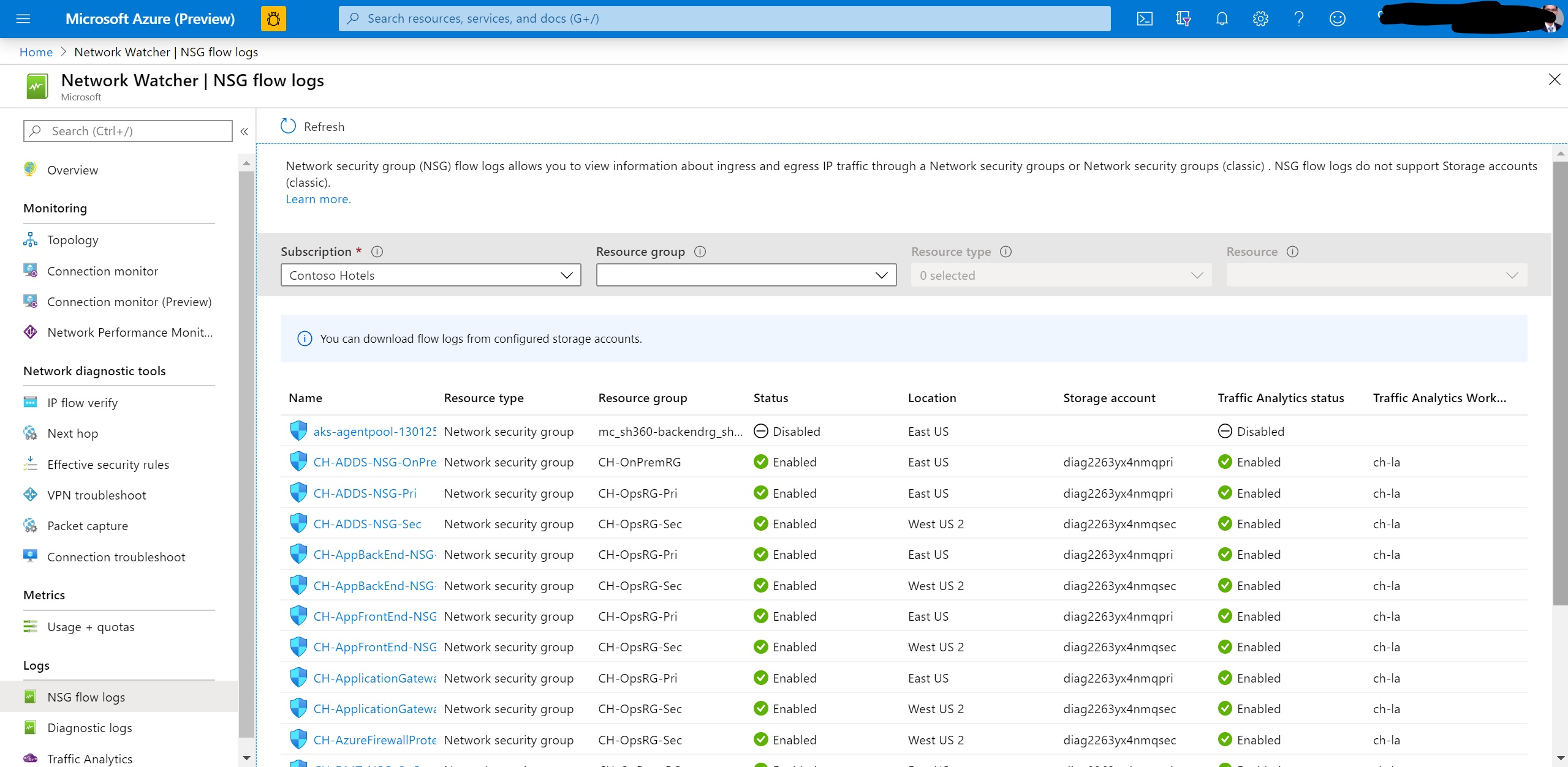
Azure portal
On the Azure portal, navigate to the NSG Flow Logs section in Network Watcher. Then click the name of the NSG. This will bring up the settings pane for the Flow log. Change the parameters you want and hit Save to deploy the changes.
PS/CLI/REST/ARM
To update parameters via command-line tools, use the same command used to enable Flow Logs (from above) but with updated parameters that you want to change.
Working with Flow logs
Read and Export flow logs
While flow logs target NSGs, they are not displayed the same as the other logs. Flow logs are stored only within a storage account and follow the logging path shown in the following example:
Visualize flow logs
Disable flow logs
When the flow log is disabled, the flow logging for associated NSG is stopped. But the flow log as a resource continues to exist with all its settings and associations. It can be enabled anytime to begin flow logging on the configured NSG. Steps to disable/enable a flow logs can be found in this how to guide.
Delete flow logs
When the flow log is deleted, not only the flow logging for the associated NSG is stopped but also the flow log resource is deleted with its settings and associations. To begin flow logging again, a new flow log resource must be created for that NSG. A flow log can be deleted using PowerShell, CLI or REST API. The support for deleting flow logs from Azure portal is in pipeline.
Also, when a NSG is deleted, by default the associated flow log resource is deleted.
To move a NSG to a different resource group or subscription, the associated flow logs must be deleted, just disabling the flow logs won’t work. After migration of NSG, the flow logs must be recreated to enable flow logging on it.
NSG flow logging considerations
Storage account considerations:
- Location: The storage account used must be in the same region as the NSG.
- Performance Tier: Currently, only standard tier storage accounts are supported.
- Self-manage key rotation: If you change/rotate the access keys to your storage account, NSG Flow Logs will stop working. To fix this issue, you must disable and then re-enable NSG Flow Logs.
Flow Logging Costs: NSG flow logging is billed on the volume of logs produced. High traffic volume can result in large flow log volume and the associated costs. NSG Flow log pricing does not include the underlying costs of storage. Using the retention policy feature with NSG Flow Logging means incurring separate storage costs for extended periods of time. If you want to retain data forever and do not want to apply any retention policy, set retention (days) to 0. For more information, see Network Watcher Pricing and Azure Storage Pricing for additional details.
Issues with User-defined Inbound TCP rules: Network Security Groups (NSGs) are implemented as a Stateful firewall. However, due to current platform limitations, user-defined rules that affect inbound TCP flows are implemented in a stateless fashion. Due to this, flows affected by user-defined inbound rules become non-terminating. Additionally byte and packet counts are not recorded for these flows. Consequently the number of bytes and packets reported in NSG Flow Logs (and Traffic Analytics) could be different from actual numbers. An opt-in flag that fixes these issues is scheduled to be available by March 2021 latest. In the interim, customers facing severe issues due to this behavior can request opting-in via Support, please raise a support request under Network Watcher > NSG Flow Logs.
Inbound flows logged from internet IPs to VMs without public IPs: VMs that don’t have a public IP address assigned via a public IP address associated with the NIC as an instance-level public IP, or that are part of a basic load balancer back-end pool, use default SNAT and have an IP address assigned by Azure to facilitate outbound connectivity. As a result, you might see flow log entries for flows from internet IP addresses, if the flow is destined to a port in the range of ports assigned for SNAT. While Azure won’t allow these flows to the VM, the attempt is logged and appears in Network Watcher’s NSG flow log by design. We recommend that unwanted inbound internet traffic be explicitly blocked with NSG.
Issue with Application Gateway V2 Subnet NSG: Flow logging on the application gateway V2 subnet NSG is not supported currently. This issue does not affect Application Gateway V1.
Incompatible Services: Due to current platform limitations, a small set of Azure services are not supported by NSG Flow Logs. The current list of incompatible services is
Best practices
Enable on critical VNETs/Subnets: Flow Logs should be enabled on all critical VNETs/subnets in your subscription as an auditability and security best practice.
Enable NSG Flow Logging on all NSGs attached to a resource: Flow logging in Azure is configured on the NSG resource. A flow will only be associated to one NSG Rule. In scenarios where multiple NSGs are utilized, we recommend enabling NSG flow logs on all NSGs applied at the resource’s subnet or network interface to ensure that all traffic is recorded. For more information, see how traffic is evaluated in Network Security Groups.
Few common scenarios:
- Multiple NICs at a VM: In case multiple NICs are attached to a virtual machine, flow logging must be enabled on all of them
- Having NSG at both NIC and Subnet Level: In case NSG is configured at the NIC as well as the Subnet level, then flow logging must be enabled at both the NSGs.
Storage provisioning: Storage should be provisioned in tune with expected Flow Log volume.
Naming: The NSG name must be upto 80 chars and the NSG rule names upto 65 chars. If the names exceed their character limit, it may get truncated while logging.
Troubleshooting common issues
I could not enable NSG Flow Logs
- Microsoft.Insights resource provider is not registered
If you received an AuthorizationFailed or a GatewayAuthenticationFailed error, you might have not enabled the Microsoft Insights resource provider on your subscription. Follow the instructions to enable the Microsoft Insights provider.
I have enabled NSG Flow Logs but do not see data in my storage account
NSG Flow Logs may take up to 5 minutes to appear in your storage account (if configured correctly). A PT1H.json will appear which can be accessed as described here.
- No Traffic on your NSGs
Sometimes you will not see logs because your VMs are not active or there are upstream filters at an App Gateway or other devices that are blocking traffic to your NSGs.
I want to automate NSG Flow Logs
Support for automation via ARM templates is currently not available for NSG Flow Logs. Read the feature announcement for more information.
What does NSG Flow Logs do?
Azure network resources can be combined and managed through Network Security Groups (NSGs). NSG Flow Logs enable you to log 5-tuple flow information about all traffic through your NSGs. The raw flow logs are written to an Azure Storage account from where they can be further processed, analyzed, queried, or exported as needed.
Does using Flow Logs impact my network latency or performance?
Flow logs data is collected outside of the path of your network traffic, and therefore does not affect network throughput or latency. You can create or delete flow logs without any risk of impact to network performance.
How do I use NSG Flow Logs with a Storage account behind a firewall?
To use a Storage account behind a firewall, you have to provide an exception for Trusted Microsoft Services to access your storage account:
- Navigate to the storage account by typing the storage account’s name in the global search on the portal or from the Storage Accounts page
- Under the SETTINGS section, select Firewalls and virtual networks
- In Allow access from, select Selected networks. Then under Exceptions, tick the box next to Allow trusted Microsoft services to access this storage account
- If it is already selected, no change is needed.
- Locate your target NSG on the NSG Flow Logs overview page and enable NSG Flow Logs with the above storage account selected.
You can check the storage logs after a few minutes, you should see an updated TimeStamp or a new JSON file created.
How do I use NSG Flow Logs with a Storage account behind a Service Endpoint?
NSG Flow Logs are compatible with Service Endpoints without requiring any extra configuration. See the tutorial on enabling Service Endpoints in your virtual network.
What is the difference between flow logs versions 1 & 2?
Flow Logs version 2 introduces the concept of Flow State & stores information about bytes and packets transmitted. Read more
Pricing
NSG Flow Logs are charged per GB of logs collected and come with a free tier of 5 GB/month per subscription. For the current pricing in your region, see the Network Watcher pricing page.
Storage of logs is charged separately, see Azure Storage Block blob pricing page for relevant prices.


