- Работа с GPIO
- Содержание
- Меры предосторожности
- Именование gpio
- Вычисление номера gpio
- Работа из userspace
- Интерфейс sysfs
- Чтение и запись
- Работа с прерываниями
- Работа через chardev
- Python
- Прямое обращение через память процессора
- Работа в ядре Linux
- Рекомендации по Device Tree
- Пример device-tree node
- GPIO (Linux)
- Contents
- Introduction
- GPIO Char Device API — libgpiod
- Torizon
- Toradex BSP Layers and Reference Images for Yocto Project — 3.0b3 Onwards
- GPIO Tool
- GPIO Sysfs
- To export a particular pin as GPIO for user control proceed as follows:
- To change that GPIO pins direction to in/out:
- To check the value (in case its direction is input):
- To change its value (in case its direction is output):
- To directly force a GPIO to output and set its initial value (e.g. glitch-free operation):
- To configure a GPIO as an interrupt source:
- To un-export aka revert the exporting of a GPIO pin:
- GPIO Libsoc
- Cross-Compiling Libsoc Examples
- Cross-Compiling Libsoc
- GPIO Power Management Keys
- GPIO Keyboard Driver
- Tag the GPIO Input Device
- GPIO Power-Off
- GPIO LED
- GPIO PPS
- GPIO U-Boot
- Command Line Interface
- Example — Colibri iMX8X
- Example — Colibri VFxx
- From Source Code
- GPIO Debugging
Работа с GPIO
ВНИМАНИЕ: статья рассчитана на разработчиков или опытных пользователей и даёт общие рекомендации того, как использовать gpio в обход официального ПО WirenBoard.
Если вам нужно работать напрямую с gpio, то мы рекомендуем делать это через драйвер wb-mqtt-gpio.
Описание доступных ножек gpio для конкретной ревизии контроллера можете посмотреть в статье GPIO.
Содержание
Меры предосторожности
- Убедитесь, что вашу задачу нельзя решить стандартными средствами программного обеспечения Wiren Board.
- Все порты Wiren Board, в том числе и GPIO, работают с напряжением 3.3V.
- Подключение сигнала с напряжением большим 3.3V к ножке GPIO грозит выходом из строя процессорного модуля.
В случае необходимости подключения устройств, работающих с более высоким напряжением, необходимо использовать схемы согласования или подключать (для 5V) через резистор в 20 кОм и более.
Именование gpio
К сожалению, четкого стандарта по именованию gpio не существует, но при работе с контроллерами WirenBoard стоит придерживаться следующих правил:
- выводы gpio сгруппированы по банкам (banks; эквивалентно gpiochips)
- каждый банк содержит 32 gpio. Нумерация банков начинается с 0.
Вычисление номера gpio
Для управления ножкой gpio нужно знать её номер. В рассматриваемых примерах будем работать с gpio A1_IN контроллера WB6.7 (номер: 109; gpiochip 3, offset 13): Вычислим банк gpio и offset, зная номер (109):
То же самое справедливо и наоборот. Зная банк и offset (3 и 13, соответственно), можно вычислить номер gpio:
Работа из userspace
Перед началом работы из userspace, необходимо убедиться, в том, что нужный gpio — свободен. Для этого можно посмотреть на вывод команды
В выводе команды видим примерно следующее:
Это значит, что gpio 0, 26 и 27 уже экспортированы в sysfs и доступны для управления. Gpio 11 и 13 заняты ядерным драйвером onewire и недоступны для использования. Остальные gpio банка 0 — свободны.
Если нужный gpio — занят, то можно остановить драйвер:
ВНИМАНИЕ: остановка драйверов может привести к неожиданному поведению контроллера. Теперь нужный gpio свободен до следующей перезагрузки.
В настоящий момент, для работы с gpio в userspace доступны 2 интерфейса: sysfs и chardev (начиная с версии ядра 4.8).
Различия между chardev и sysfs хорошо описаны в этой статье. Sysfs имеет статус deprecated, поэтому, по возможности, стоит работать через chardev.
Интерфейс sysfs
Для работы через sysfs c определённым GPIO его надо экспортировать:
Здесь и далее N — номер gpio
Экспортированные gpio появляются в каталоге /sys/class/gpio :
В директории /sys/class/gpioN теперь находятся файлы для работы с GPIO (где N — номер GPIO, как и было сказано ранее):
Установка направления GPIO (ввод/вывод) производится с помощью записи в файл direction
Чтение и установка значения GPIO производится с помощью файла value .
Чтение и запись
- Находим номер GPIO, соответсвующий вашей версии контролера нужному клеммнику в таблице WB2.8. Для клеммника номер 2 в версии 2.8 это GPIO 32.
- Экспортируем GPIO в sysfs
Работа с прерываниями
Через интерфейс sysfs можно запросить прерывания по изменению состояния процессора.
Установка прерывания производится путём записи значения в файл «edge». Значения могут быть:
- none — отключить прерывание
- rising — включить прерывание по нисходящему фронту
- falling — включить прерывание по восодящему фронту
- both — включить прерывание по обеим фронтам.
Пример работы с прерываниями:
Прерывания можно ловить из userspace с помощью системного вызова epoll() и select() на файл value. Пример работы см. [1]
Работа через chardev
Представленный в ядре 4.8 интерфейс chardev имеет C/Python библиотеку libgpiod и userspace-утилиты для работы с gpio. Исходный код библиотеки и документация доступны в репозитории libgpiod.
Утилиты распространяются в составе debian-пакетов gpiod и libgpiod-dev для debian buster и новее. К сожалению, для stretch пакетов в официальных репозиториях нет.
Если нужно установить libgpiod в debian stretch, можно воспользоваться сторонними репозиториями (например, этим). Используйте сторонние репозитории на свой страх и риск; компания WirenBoard не контролирует их содержимое.
Для работы с gpio из bash в пакете gpiod поставляются следующие утилиты:
- gpiodetect — информация обо всех банках gpio в системе
- gpioinfo — подробная информация обо всех линиях gpio определённого банка
- gpioget — возвращает значение определённого gpio
- gpioset = = — устанавиливает состояние на определенные линии gpio
- gpiofind — возвращает номер gpio
- gpiomon — отслеживание событий gpio
Примеры использования gpiod можно посмотреть в [2] и [3]
Python
Для управления gpio из python был написан модуль
Модуль представляет собой обёртку вокруг sysfs. Исходный код доступен на нашем github.
Модуль позволяет работать с gpio в синхронном и асинхронном (с регистрацией коллбэков) режимах.
Прямое обращение через память процессора
Этот метод настоятельно НЕ РЕКОМЕНДУЕТСЯ для использования без достаточных оснований. Для работы из С/C++ стоит использовать работу через файлы в sysfs или chardev, как описано в предыдущих разделах.
Управлять GPIO можно с помощью прямого доступа к регистрам процессора, в обход Linux, через интерфейс /dev/mem. При этом, по сравнению с работой через sysfs минимизируются накладные расходы. Этот метод можно использовать, если вам необходим очень быстрый доступ к GPIO, например bitbang протоколов или ШИМ. Стоит иметь в виду, что планировщик процессов всё ещё может вносить в работу программы значительные задержки. Рекомендуется выносить критичные ко времени задачи в ядро.
Работа в ядре Linux
Ознакомиться с ядром Linux, использующимся в контроллерах WirenBoard можно в нашем репозитории ядра.
Рекомендации по Device Tree
Device-tree, использующиеся на контроллерах WirenBoard, доступны в репозитории ядра. Разные аппаратные ревизии контроллера используют разные dts (например, dts для WB6.X можно найти здесь)
Указывать GPIO в Device Tree необходимо для настройки работы GPIO в режиме программного SPI, I2C, для использования GPIO в качестве источника прерываний и т.д. Так, например, на пин 10@UEXT1 (CS) и пины 5@UEXT2 (SCL), 6@UEXT2 (SDA), 10@UEXT2 (CS) выведены линии GPIO процессора. Их можно сконфигурировать для использования, например, в качестве chip-select для SPI или в качестве I2C.
GPIO процессора и периферийных устройств разбиты на банки (gpiochip). GPIO процессора разбиты на 3 банка по 32 GPIO: gpio0, gpio1, gpio2. Адресация GPIO в Device Tree происходит по номеру банка и номеру GPIO *внутри* банка.
Пример device-tree node
Определим сигнал 6@UEXT2 (SDA) в качестве источника прерываний для драйвера mrf24j40. Согласно таблице Список GPIO, сигнал соответствует GPIO 53 процессора. 53 принадлежит второму банку gpio (от 32 до 63). Номер GPIO внутри банка 53-32=21 :
Источник
GPIO (Linux)
Contents
Introduction
Please note that pin configuration/muxing is a non-trivial part of the overall system design. It is easily possible to do illegal configurations when it comes to multiplexed pins (e.g. one pin driving low and the other one driving high). Even more though on SoCs where certain settings in this respect cannot be done per pin but rather only per pin group.
GPIO Char Device API — libgpiod
Since the long famous sysfs GPIO interface (/sys/class/gpio) has been deprecated, the GPIO Char Device API, also known as libgpiod has been adopted by the Linux kernel community as the replacement. The sysfs interface is still supported by Toradex BSPs but you are discouraged to use it.
Torizon
Torizon is preferred for using libgpiod, due to ease-of-use and a smoother application development experience. Visit the article below for instructions on how to use it:
Toradex BSP Layers and Reference Images for Yocto Project — 3.0b3 Onwards
libgpiod is supported and can be used on Toradex BSP Layers and Reference Images for Yocto Project from the release 3.0b3 onwards. The userspace tools and libraries are included in our evaluation image. You can learn how to use the command-line tools and the C API in the article below:
Warning: you have to adapt the instructions to the fact that the reference images do not come with a container engine.
GPIO Tool
The Toradex GPIO tool can be used to read the current pin configuration or to temporally change the pin configuration and GPIO state. It can either be started from the launcher on the desktop or through the command line as follows:
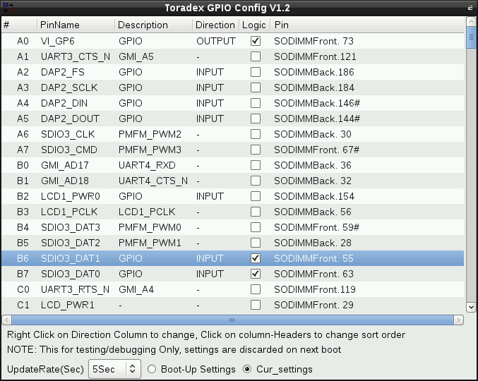
Toradex GPIOConfig utility
The GPIO Tool does not support i.MX 8/8X modules. Pin muxing on i.MX8/8X SoC is exclusively handled by the system control unit firmware aka SCFW, only the Linux kernel pin control subsystem can change the pin muxing by parsing the device tree. The GPIO Tool, as a userspace application, is not allowed to do pin muxing, thus it is not possible to update it to support i.MX8/X SoCs.
GPIO Sysfs
Warning: The GPIO sysfs is deprecated and has been discontinued. Its use for BSP 3.0 is discouraged and will be removed. For Torizon use the new char device API and LIBGPIOD libraries and tools. See the GPIO Char Device API — libgpiod article for reference.
To use pins other than the already exported ones directly from userspace through sysfs they first have to be exported as GPIOs.
Warning: For i.MX 6 based modules you need to make sure that the pin is actually muxed as a GPIO in the device-tree or platform data. Failing to do so will not give any error. The pin will simply report 0 if configured as an input and not react to any state change if configured as an output.
Note: Use the module datasheet to find what SoC pin(s) are routed to what module edge connector pin and the carrier board datasheet or schematic to find where those signals go to.
Note: E.g. the Tegra SoC defines GPIOs with an alphanumeric term, e.g. X5 but the Linux kernel uses a numeric-only representation in its GPIO subsystem and in the sysfs interface to the GPIO functionality.
Note: The relationship between SOC GPIO names and the ‘magic’ numbers used here can be found on this page.
In the following example, we are going to use SODIMM pin 100 of a Colibri T20. This makes for the following relationship:
| SODIMM Pin Number | SODIMM Pin Name | SoC Pin Name | SoC GPIO Function Name | Kernel GPIO Number | Evaluation Board Connector |
|---|---|---|---|---|---|
| 100 | nPXCVREN | SPI1_SCK | X5 | 189 | X9. 7 |
To export a particular pin as GPIO for user control proceed as follows:
To change that GPIO pins direction to in/out:
To check the value (in case its direction is input):
Warning: On i.MX based modules one cannot read back the value which has been set to an output unless one did set the SION bit in the pin muxing.
To change its value (in case its direction is output):
To directly force a GPIO to output and set its initial value (e.g. glitch-free operation):
To configure a GPIO as an interrupt source:
Note: If a GPIO is configured as an input, one can configure the GPIO as an interrupt source. Configure GPIO if the interrupt occurs when the GPIO signal has a rising edge, a falling edge, or interrupts on both rising and falling edges.
- rising: Trigger on rising edge
- falling: Trigger on falling edge
- both: Trigger on both edges
- none: Disable interrupts on both edges
To un-export aka revert the exporting of a GPIO pin:
Warning: GPIOs which are already used in the drivers can not be controlled from sysfs, unless a driver explicitly exported that particular pins GPIO.
More information concerning the Linux’ GPIO subsystem can be found in the following kernel documentation file:
GPIO Libsoc
Warning: Libsoc is deprecated on Toradex BSPs — this section is kept only for reference. Its use for BSP 3.0 is discouraged and will be removed. For Torizon use the new char device API and LIBGPIOD libraries and tools. See the GPIO Char Device API — libgpiod article for reference.
Libsoc is a C library to interface with common peripherals found in System on Chips (SoC) through generic Linux Kernel interfaces. Libsoc is integrated with Embedded Linux BSP starting from release 2.8b3. The Sysfs GPIO access is file-based and Libsoc userspace library uses the sysfs gpio interface. Please refer to https://github.com/jackmitch/libsoc for more information.
Note: When using Libsoc instead of Sysfs GPIO directly the mapping from SoC GPIO representation to Linux GPIO number is abstracted, therefore inside a Toradex Computer on Module family (e.g Apalis, Colibri or Verdin) the GPIO number corresponds to the CoM edge connector (i.e. MXM3 or SODIMM) pin number, making the application more easily portable between modules (e.g. Apalis iMX6 and Apalis T30).
Cross-Compiling Libsoc Examples
Build and install the OE-core aka Yocto SDK in your host machine. For instructions related to building and installing the SDK, have a look at the Linux SDKs knowledge-base article.
Examples are provided below. To cross-compile:
For available machines, have a look in Makefile, e.g.:
Copy the binary to the target via ssh and run the example. E.g.:
Cross-Compiling Libsoc
If you are using an Embedded Linux BSP aka Linux image prior to 2.8b3 then you have to build Libsoc and deploy to the device.
Please refer to /libsoc/contrib/board-files/ path to get conf file name. E.g.:
For instance, for Apalis iMX6 the board in Libsoc is apalis-imx6. For Colibri iMX7 512MB it is colibri-imx7-512mb and so on.
The example below is provided for Colibri VF61:
Note: If you are building for Colibri iMX7 then modify MACHINE=colibri-imx7 make -j3.
Deploy the library and conf file to the target via ssh and run the example:
GPIO Power Management Keys
Linux systems use key events to initiate a clean shutdown or suspend-to-memory sequence. On a typical PC, pressing the power button generates a key event which will lead to a shutdown of the system. For an embedded system, a GPIO with a key code assigned can be used to trigger key events. When the key is pressed (GPIO triggered), the system will initiate the sequence.
The systemd service systemd-logind is the user-space program listening to key events (if they are tagged with the string «power-switch», see below). Four key codes are supported:
- KEY_POWER = initiate shutdown
- KEY_POWER2 = initiate shutdown
- KEY_SLEEP = suspend-to-ram, commonly known as «suspend»
- KEY_SUSPEND = suspend-to-disk, commonly known as «hibernate»
There are two steps required:
- Declare a GPIO as an input device and assign a key code using the GPIO keyboard driver
- Use a udev rule to tag the GPIO input device
GPIO Keyboard Driver
For device tree enabled kernels, a node as follows can be used in the carrier board device tree file:
For details on how to customise the device tree refer to the Device Tree Customization article.
For Apalis T30, the predefined macro POWER_GPIO in the board file can be enabled to enable the power key code (see this commit). For the Colibri T20/T30 boards a similar approach can be adopted.
For Colibri T30, the example below enables SODIMM Pin 162 as a suspend pin
Tag the GPIO Input Device
Use a udev rule to add the power-switch tag to the GPIO key event source. Store the file in a udev rules directory, e.g. /etc/udev/rules.d/power-key.rules
With that, all keycodes get tagged as power-switch events, and systemd will interpret the relevant key codes. The exact behaviour can be fine-tuned through HandlePowerKey/HandleSuspendKey and HandleHibernateKey in /etc/systemd/logind.conf.
GPIO Power-Off
To power off a system completely after shutdown, often a GPIO is needed to switch off the system. Newer Kernel provides a specific GPIO power-off driver to achieve this.
Our Colibri and Apalis Evaluation Boards have a push button power on/off controller (LTC2954) which has a GPIO input FORCE_OFF# (X4-5 on Colibri or X61-5 on Apalis). This signal makes sure that the DC-DC converter on the carrier board are switched-off completely as if the user pressed the on/off button. After connecting these signals to a GPIO, the GPIO power-off driver needs to be enabled. On device-tree based kernels (e.g. Colibri/Apalis iMX6 and Colibri VF50/VF61), the driver CONFIG_POWER_RESET_GPIO need to be enabled (up to v2.3Beta5 this is not the case by default). Furthermore, on Colibri VF50/VF61 using V2.7 and newer releases the default power off method needs to be disabled by reverting commit ARM: vf610: PM: register power_off function. Finally, a new node needs to be added which specifies the GPIO to switch power off. This example uses SO-DIMM 135 (EXT_IO_0) as power-off GPIO for Colibri VF50/VF61 modules:
The poweroff command needs to be used to power-off the system completely («halt» does not work):
For Apalis T30, the predefined macro FORCE_OFF_GPIO in the board file can be enabled (see this commit). For the Colibri T20/T30 boards, a similar approach can be adopted.
For i.MX6 based modules CONFIG_POWER_RESET_GPIO must be set in the kernel configuration. Additionally, for the 3.10.17 kernel version, you will have to at least cherry-pick this commit or use the toradex_imx_3.10.17_1.0.0_ga-next branch.
Note: To have gpio-poweroff driver working well on i.MX6 with new kernel versions >= toradex_4.14-2.0.x-imx, you should add the property force-mode to the gpio-poweroff node.
For i.MX8/8X based modules CONFIG_POWER_RESET_GPIO must be set in the kernel configuration. You also need to correctly mux the GPIO pin that you choose to use. Here is an example of device tree that uses SO-DIMM 104 as power-off GPIO for Colibri iMX8X:
GPIO LED
The GPIO LED driver allows using a GPIO to control a LED. Using the Kernels LED driver framework has the advantage that triggers can be specified, which allow using an LED as a visual activity signal for various system activities.
You can also get a list of valid triggers (and configure the active trigger) through the sysfs file at /sys/class/leds/user1/trigger.
GPIO PPS
The GPIO PPS is a feature present in the Linux Kernel that allows the usage of a GPIO with a given Pulse-Per-Second (PPS) signal.
Starting from BSP 5, it’s enabled by default in the kernel config on Toradex Reference Images for Yocto Project and TorizonCore:
Here is one example of a device tree for Colibri iMX7D 1GB. In addition to the example, you must also make sure to check the pin muxing, i.e. make sure that no other driver muxes and claims the pin function GPIO1_IO02, and to mux the pin to gpio as part of the pps node.
Also note that since pps is a new node, it must be created somewhere in the tree under / .
Please refer to the Linux kernel documentation on device tree bindings for more details: Device-Tree Bindings for a PPS Signal on GPIO
GPIO U-Boot
One can also access GPIOs from U-Boot. This allows one to implement functionality such as “Press button X and turn the device ON to upgrade firmware” using U-Boot scripts.
The GPIO driver can be used from within the U-Boot source code. Additionally, the GPIO driver has a corresponding gpio command-line interface that can be used to set and get GPIO values. Note that for the command-line interface to work the corresponding pin must be muxed to its GPIO functionality in the U-Boot code.
On a Colibri VF accesses from code allow to set a GPIO around 40ms, access from the command-line interface in ‘bootcmd’ 70ms after power-up.
Note: The relationship between SOC GPIO names and the ‘magic’ numbers used here can be found on this page.
Command Line Interface
To set the GPIO:
To clear the GPIO
To toggle the GPIO
To read the state of GPIO:
Usually, all GPIO pins are muxed as input in U-Boot. You can confirm it, for instance, with the command below:
Example — Colibri iMX8X
This example has been tested on Colibri iMX8QXP + Colibri Evaluation Board V3.2 using the mainline master branch of U-Boot.
To calculate the pin number in U-Boot, use the formula below:
Warning: beware that this formula is different from the formula for the Linux user space provided in GPIO Alphanumeric to GPIO Numeric Assignment.
Change the pinmux configuration in the U-Boot device tree, in the source code. The change below set the GPIO on SODIMM 45 as output:
Re-compile and deploy U-Boot, then toggle this GPIO from the U-Boot command-line:
Example — Colibri VFxx
To clear GPIO #22 (Backlight PWM configured as GPIO on a Colibri VF) do:
To read GPIO #10 (UART A, DTR on a Colibri VF) do:
To read GPIO #10 (UART A, DTR on a Colibri VF) and react on the read value do:
From Source Code
To access a GPIO earlier than what would be possible from the U-Boot command line or to include it in an algorithm written in source code using the GPIO API. In most cases this code would live in the board file (e.g. board/toradex/colibri_vf/colibri_vf.c).
The GPIO’s need to be configured only after the GPIO driver is loaded, if a GPIO gets configured before the driver has been loaded, the GPIO functions will have no effect. The ‘board_init’ function is called just after GPIO initialization and hence is an appropriate place to configure custom GPIO’s.
e.g. To set GPIO_10 during boot from board file:
GPIO Debugging
All «free» Pins are configured as GPIOs by default and are already exported from within the board-specific platform configuration to be used from userspace through the sysfs interface.
To know what GPIOs are currently exported from the platform configuration resp. requested from drivers proceed as follows:
Источник


