- Sparkfun pro micro windows driver
- About
- SparkFun Pro Micro — RP2040
- Pro Micro & Fio V3 Hookup Guide
- Introduction
- Pro Micro
- Pro Micro — 3.3V/8MHz
- Pro Micro — 5V/16MHz
- FioV3
- Fio v3 — ATmega32U4
- Covered In This Tutorial
- Suggested Reading
- Serial Communication
- What is an Arduino?
- Installing Arduino IDE
- Hardware Overview: Pro Micro
- The Pinout
- Power Pins
- I/O Pins
- On-Board LEDs
- 3.3V or 5V? 8MHz or 16MHz?
- Board Dimensions
- How to Power the Pro Micro
- Battery Technologies
- February 6, 2013
- How to Power a Project
- February 7, 2013
- Hardware Overview: Fio v3
- The Pinout
- Power Pins
- I/O Pins
- On-Board LEDs
- How to Power the Fio v3
- Using the LiPo Charger
- Connecting An XBee
- Installing: Windows
- Windows Driver Installation
- Step 1: Download the Driver
- Step 2: Plug in the Pro Micro / Fio v3
- Step 3: Open the Device Manager
- Step 4: Finding the Driver
- Installing the Arduino Addon
- Using the Board Manager
- Installing the .brd Files Manually
- Installing: Mac & Linux
- Board Installation
- Using the Board Manager
- Installing the .brd Files Manually
- Installing the Arduino Addon
- Example 1: Blinkies!
- Upload the RX/TX Blinky, Hello World Sketch
- Understanding the Sketch
- Why Does My Board Re-Enumerate Every Upload?
- Example 2: HID Mouse and Keyboard
- What is HID?
- Example 2a: USB Keyboards Made Simple
- Example 2b: USB Mouse Functionality
- Troubleshooting and FAQ
- Serial Port Not Showing Up in ‘Tools > Board’ Menu
- Reset to Bootloader
- Code Runs After Upload But Fails to Start After Power Cycle
- Frequently Asked Questions
- What are VID and PIDs?
- How Can I Change the VID and PID on an ATMega32U4 Board?
- Why Does my ATMega32U4 Board Show up Twice in Device Manager?
- How Does the IDE Know Which COM Port to Use?
- How Do I Reinstall the Bootloader?
- Resources and Going Further
Sparkfun pro micro windows driver

The Pro Micro is a micro controller with an ATMega32U4 IC on board. The USB transceiver is inside the 32U4, adding USB connectivity on-board without external USB interfaces. This comes in both a 3.3V and 5V version.
- /Documentation — Data sheets (.pdf and .svg)
- /Firmware — Arduino example code used in the hookup guide
- /Hardware — All Eagle design files (.brd, .sch, .STL)
- /Production — Test bed files and production panel files
- Hookup Guide — Basic hookup guide for the Pro Micro.
- SparkFun Arduino Board Addon — Arduino board addon for Pro Micro.
- SparkFun Graphical Datasheets — Graphical datasheets for various SparkFun products.
- DEV-12587- 3.3V/8MHz version
- DEV-12640- 5V/16MHz version
This product is open source!
Please review the LICENSE.md file for license information.
If you have any questions or concerns on licensing, please contact techsupport@sparkfun.com.
Distributed as-is; no warranty is given.
- Your friends at SparkFun.
About
ATMega32U4 Arduino board, available from SparkFun Electronics
SparkFun Pro Micro — RP2040
Creative Commons images are CC BY 2.0
The SparkFun Pro Micro RP2040 is a low-cost, high performance board with flexible digital interfaces featuring the Raspberry Pi Foundation’s RP2040 microcontroller. Besides the good ‘ol Pro Micro footprint, the board also includes a WS2812B addressable LED, boot button, reset button, Qwiic connector, USB-C, resettable PTC fuse, and castellated pads.
The RP2040 utilizes dual ARM Cortex-M0+ processors (up to 133MHz) and features:
- 264kB of embedded SRAM in six banks
- 6 dedicated IO for SPI Flash (supporting XIP)
- 30 multifunction GPIO
- Dedicated hardware for commonly used peripherals
- Programmable IO for extended peripheral support
- Four channel ADC with internal temperature sensor, 0.5 MSa/s, 12-bit conversion
- USB 1.1 Host/Device
The RP2040 is supported with both C/C++ and MicroPython cross-platform development environments, including easy access to runtime debugging. It has UF2 boot and floating-point routines baked into the chip. The built-in USB can act as both device and host. It has two symmetric cores and high internal bandwidth, making it useful for signal processing and video. While the chip has a large amount of internal RAM, the board includes an additional 16MB external QSPI flash chip to store program code.
The SparkFun Qwiic Connect System is an ecosystem of I 2 C sensors, actuators, shields and cables that make prototyping faster and less prone to error. All Qwiic-enabled boards use a common 1mm pitch, 4-pin JST connector. This reduces the amount of required PCB space, and polarized connections mean you can’t hook it up wrong.
RP2040 General Features
- Dual Cortex M0+ processors, up to 133 MHz
- 264 kB of embedded SRAM in 6 banks
- 6 dedicated IO for QSPI flash, supporting execute in place (XIP)
- 30 programmable IO for extended peripheral support
- SWD interface
- Timer with 4 alarms
- Real time counter (RTC)
- USB 1.1 Host/Device functionality
- Supported programming languages
- MicroPython
- C/C++
SparkFun Pro Micro — RP2040 Features
- Raspberry Pi Foundation’s RP2040 microcontroller
- AP2112 3.3V voltage regulator
- Support programming languages
- MicroPython
- C/C++
- On-board USB-C connector for programming
- USB 1.1 Host/Device functionality
- Built-in Resettable PTC Fuse
- PTH pads w/ castellated edges
- 20x multifunctional GPIO Pins [1]
- 4x 12-bit ADC channels with internal temperature sensor, 0.5 MSa/s, 12-bit
- 10x PWM channels
- Serial Peripherals
- 2x UARTs
- 1x I 2 C (Qwiic enabled)
- 1x SPI
- Buttons
- Boot
- Reset
- LEDs
- Power
- WS2812 Addressable LED
- 16MB External Flash Memory
- Dimensions: 1.3in x 0.7in
[1] Note: The GPIO pins are muxed so you can reconfigure the pins for the digital interface of your choice! Check out the RP2040 datasheet for more information on the pins that are broken out on the board.
Pro Micro & Fio V3 Hookup Guide
Introduction
Welcome to the new frontier of Arduino-compatible boards, made possible by the ATmega32U4. No longer does your Arduino need to be harnessed by an FTDI Cable, or an ATmega8U2, or any chip who’s sole purpose is acting as an intermediary between your Arduino and your computer.
Pro Micro
The SparkFun Pro Micro [ 3.3V/8MHz and 5V/16MHz ] is a really cool, little development board. It’s an Arduino-compatible microcontroller, micro-sized, and it accomplishes with one single chip what old Arduino Unos, Duemilanoves, and Diecimeillas could never dream of: true USB functionality.
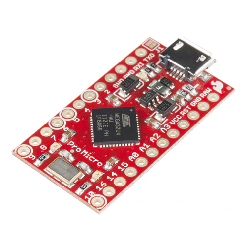
Pro Micro — 3.3V/8MHz
Here at SparkFun, we refuse to leave ‘good enough’ alone. That’s why we’re adding to our line-up of Arduino-compatible microc…
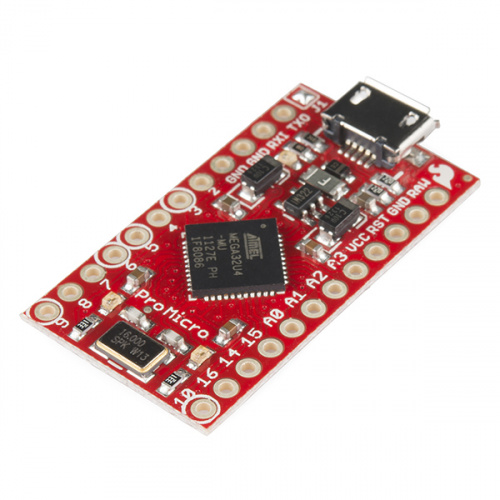
Pro Micro — 5V/16MHz
Here at SparkFun, we refuse to leave ‘good enough’ alone. That’s why we’re adding to our line-up of Arduino-compatible microc…
FioV3
This tutorial also covers the Fio v3, which works a lot like the Pro Micro but adds features like easy XBee interfacing and LiPo charging.
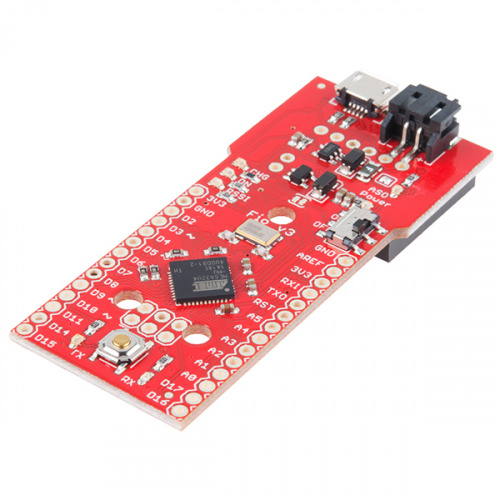
Fio v3 — ATmega32U4
The Fio v3 is a new spin on the Arduino Fio hardware powered by the ATmega32U4.Not only is it small and LiPo-ready, it’s a ve…
Covered In This Tutorial
This tutorial aims to introduce you to both the hardware and firmware sides of the Pro Micro (and Fio v3). We’ll also dedicate a few pages to helping install the boards on Windows and Mac. Here’s a summary of what will be covered:
- Hardware Overview: Pro Micro — An overview of the pinout and hardware features of the Pro Micro.
- Hardware Overview: Fio v3 — An overview of the pinout and hardware features of the Fio v3.
- Installing on Windows — How to install the drivers and Arduino addon on Windows.
- Installing on Mac/Linux — How to install the drivers and Arduino addon on Mac.
- Example 1: Blinkies — A simple «Hello, world» sketch specifically suited to the Pro Micro and Fio v3.
- Example 2: HID Mouse and Keyboard — An introduction to the HID USB capability of the Pro Micro. How to emulate USB keyboards and mice!
- Troubleshooting and FAQ — Helpful troubleshooting tips and tricks for getting the most out of the Pro Micro.
Suggested Reading
Before delving into this tutorial, here are some concepts you should be familiar with. If you’re not, consider checking out the related tutorial first.
- What is Arduino? — An introduction to the Arduino platform and IDE.
- How to Install Arduino — A general installation guide for Arduino.
- Serial Communication — Serial is a great, easy-to-use communication protocol.
Serial Communication
What is an Arduino?
Installing Arduino IDE
Hardware Overview: Pro Micro
Before we get into installing and using the Pro Micro, let’s quickly look at the board — examine its inputs, outputs, and other hardware quirks.
The Pinout
All of the Pro Micro’s I/O and power pins are broken out to two, parallel headers. Some pins are for power input or output, other pins are dedicated I/O pins. Further, the I/O pins can have special abilities, like analog input. Here’s a map of which pin is where, and what special hardware functions it may have:
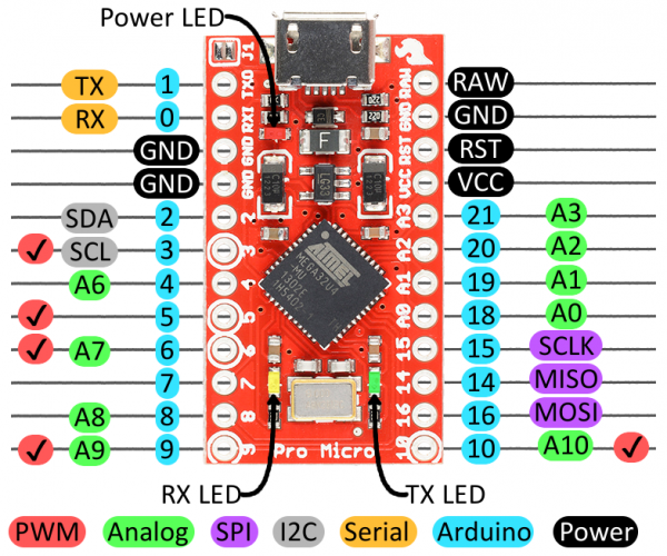
Delving a little further into which pins do what.
Power Pins
There are a variety of power and power-related nets broken out:
- RAW is the unregulated voltage input for the Pro Micro. If the board is powered via USB, the voltage at this pin will be about 4.8V (USB’s 5V minus a schottkey diode drop). On the other hand, if the board is powered externally, through this pin, the applied voltage can be up to 12V.
- VCC is the voltage supplied to the on-board ATmega32U4. This voltage will depend on whether you’re using a 3.3V/8MHz Pro Micro or a 5V/16MHz version, it’ll be either 3.3V or 5V respectively. This voltage is regulated by the voltage applied to the RAW pin. If the board is powered through the ‘RAW’ pin (or USB), this pin can be used as an output to supply other devices.
- RST can be used to restart the Pro Micro. This pin is pulled high by a 10k&Ohm; resistor on the board, and is active-low, so it must be connected to ground to initiate a reset. The Pro Micro will remain «off» until the reset line is pulled back to high.
- GND, of course, is the common, ground voltage (0V reference) for the system.
I/O Pins
The Pro Micro’s I/O pins — 18 in all — are multi-talented. Every pin can be used as a digital input or output, for blinking LEDs or reading button presses. These pins are referenced in the Arduino IDE via an integer value between 0 and 21. (The A0-A3 pins can be referenced digitally using either their analog or digital pin number).
Nine pins feature analog to digital converters (ADCs) and can be used as analog inputs. These are useful for reading potentiometers or other analog devices using the analogRead([pin]) function.
There are five pins with pulse width modulation (PWM) functionality, which allows for a form of analog output using the analogWrite([pin], [value]) function. These pins are indicated on-board with a faint, white circle around them.
There are hardware UART (serial), I 2 C, and SPI pins available as well. These can be used to interface with digital devices like serial LCDs, XBees, IMUs, and other serial sensors.
The Pro Micro has five external interrupts, which allow you to instantly trigger a function when a pin goes either high or low (or both). If you attach an interrupt to an interrupt-enabled pin, you’ll need to know the specific interrupt that pin triggers: pin 3 maps to interrupt 0 (INT0), pin 2 is interrupt 1 (INT1), pin 0 is interrupt 2 (INT2), pin 1 is interrupt 3 (INT3), and pin 7 is interrupt 4 (INT6).
On-Board LEDs
There are three LEDs on the Pro Micro. One red LED indicates whether power is present.
The other two LEDs help indicate when data is transferring over USB. A yellow LED represents USB data coming into (RX) the the Pro Micro, and a green LED indicates USB data going out (TX).
3.3V or 5V? 8MHz or 16MHz?
Pro Micros come in two flavors, which vary by system voltage and operating frequency. The standard 5V Pro Micro runs at 16MHz, and is very comparable to an Arduino Leonardo, while the 3.3V version of the Pro Micro runs at half the speed (to remain in the safe operating zone at the lower voltage) — 8MHz.
The operating voltage of your Pro Micro determines the maximum allowable voltage on any of the I/O pins. For example, if you have a 3.3V Pro Micro, don’t interface it with something that outputs 5V.
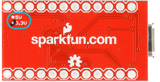
Don’t forget which version you have! We’ll need to differentiate between the two when we get to uploading code in Arduino. If you’re not sure which version you have, check the back corner of the board. One of two boxes should be checked to indicate the operating voltage.
Board Dimensions
The Pro Micro is 1.30″x0.70″. Note that the USB connector adds a small bit of length to the board so the total length is about 1.37″.
How to Power the Pro Micro
As the Pro Micro’s main feature is its innate USB functionality, the most common way to power it is via USB. In this setup, a 5V Pro Micro will be powered directly from the USB bus and a 3.3V Pro Micro will regulate the 5V supply coming in from USB down. The other end of the USB cable can be connected to either a computer, USB hub, or a USB wall adapter, which can (in most cases) provide more power.
Alternatively, if your Pro Micro is living out in the wild, out of reach of USB cables, it can be powered through either the ‘RAW‘ or ‘VCC‘ pins. A supply going into the ‘RAW’ pin will be regulated down to the correct operating voltage (5V or 3.3V). To be safe, it shouldn’t be any higher than 12V, and it should be at least 1V more than the Pro Micro’s operating voltage (e.g. >6V for a 5V Pro Micro).
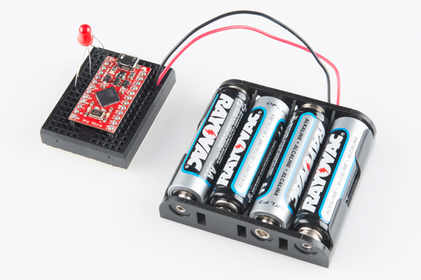
If you power the Pro Micro through the ‘VCC’ pin, keep in mind that this signal is unregulated. Only use this if you have a clean, regulated 3.3V or 5V supply to connect to it.
How, exactly, you power your project is up to you and the demands of your project. If you’re making something battery powered, you may want to opt for the 3.3V Pro Micro, which could be powered by a LiPo battery or a couple alkalines. Make sure to check out the following tutorials for more information.
Battery Technologies
February 6, 2013
How to Power a Project
February 7, 2013
Hardware Overview: Fio v3
On this page we’ll examine the hardware half of the Fio v3, looking at the pinout, layout, and schematic of the board.
The Fio v3 is like an elongated Pro Micro. On one end, it’s shape and pinouts are similar to it’s ATmega32U4 sibling. The other end of the Fio v3 is what makes it unique: a footprint for an XBee on the bottom, and a LiPo charging circuit on the top.
The Pinout
All of the Fio v3’s pins are broken out to either side of the board. Some pins are for power input or output, other pins are dedicated I/O pins. Further, the I/O pins can have special abilities, like analog input, or serial input/output. Here’s a map of which pin is where, and what special capabilities it may have:
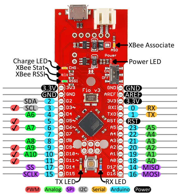
Power Pins
The pins labeled ‘3.3V‘ break out the operating voltage source of the ATmega32U4. As long as the board is powered through the white JST connector or USB, this voltage is regulated down to 3.3V. These pins can be used as outputs to supply 3.3V to other devices.
The ‘RST‘ pin can be used to restart the Fio. This pin is pulled high by a 10kΩ resistor on the board, and is active-low, so it must be connected to ground to initiate a reset. The Fio will remain off until the reset line is pulled back to high.
I/O Pins
Many of the Fio’s I/O pins are multi-talented. Every pin can be used as a digital input or output, for blinking LEDs or reading button presses. These pins are referenced in the Arduino IDE via an integer value between 0 and 23. (The A0-A10 pins can be referenced digitally via either their analog pin number or digital pin number).
Eleven pins feature analog to digital converters (ADCs) and can be used as analog inputs. These are useful for reading potentiometers or other analog devices using the analogRead([pin]) function.
There are six pins with pulse width modulation (PWM) functionality, which allows for a form of analog output using the analogWrite([pin], [value]) function. These pins are indicated on-board with a faint white circle around the pin.
There are also hardware UART (serial), I 2 C, and SPI pins available. These can be used to interface with digital devices like serial LCDs, IMUs, and other serial sensors.
The Fio v3 has five external interrupts, which allow you to instantly trigger a function when a pin goes either high or low (or both). If you attach an interrupt to an interrupt-enabled pin, you’ll need to know the specific interrupt that pin triggers: pin 3 maps to interrupt 0 (INT0), pin 2 is interrupt 1 (INT1), pin 0 is interrupt 2 (INT2), pin 1 is interrupt 3 (INT3), and pin 7 is interrupt 4 (INT6).
On-Board LEDs
There are a variety of LEDs on the Fio, the simplest of which is the red power indicator. Two LEDs towards the bottom — labeled RX and TX — help indicate when data is transferring to and from the Fio through USB. A blue LED represents USB data coming into (‘RX’) the the Pro Micro, and a yellow LED indicates USB data going out (‘TX’).
There are three LEDs tied to the XBee interface in particular: stat, RSSI, and associate. The red LED labeled ‘ON‘ is connected to the XBee’s pin 13 — DIO9 — which is, by default, set to indicate the XBee module’s ON/OFF status. An ‘RSSI‘ LED connects to XBee pin 6 (PWM0) which defaults to indicate RSSI (received signal strength) — a brighter LED means a stronger received signal. Lastly, the ‘ASO‘ LED connects to XBee pin 15, which will blink if the module is associated.
Finally, there’s a yellow LED labeled ‘CHG‘ which indicates if an attached lithium polymer battery is charging. If a battery is not connected to the Fio, the LED will be in an undefined state, and most likely be illuminated.
How to Power the Fio v3
The suggested power supply for the Fio v3 is any single-cell lithium polymer (LiPo) battery. These batteries have a nominal voltage of 3.7V, which is perfect for supplying power to the 3.3V-operating Fio. LiPos are awesome, because they’re rechargeable and still pack a lot of power into a tiny space. Any of our single cell LiPos with JST terminators can connect directly to the Fio’s onboard JST connector.
As an (immobile) alternative to batteries, the Fio can be powered directly through the USB connector.
Using the LiPo Charger
The Fio v3 has a LiPo charge management circuit (based around the MCP73831) built onto it, which handles the signal conditioning required to safely charge a single-cell LiPo battery.
To use the charge circuit, you’ll obviously need a single-cell LiPo battery plugged into the Fio. Then connect the board up via USB, so the charge circuit has a primary voltage source to supply charge to the battery.
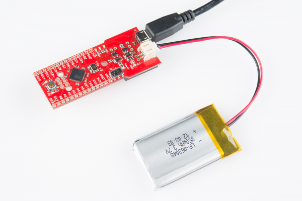
The ‘CHG’ LED will indicate the status of the battery charge. If it’s on, the battery is still charging. Once the ‘CHG’ LED goes off, the battery is fully charged.
The charge circuit is programmed to charge the battery at 500mA, so, to be safe, the battery should be no smaller than 500mAH in capacity.
Connecting An XBee
The XBee-footprint connectors on the bottom of the Fio v3 are what make it so unique. This product is designed to provide a simple interface between Arduino and XBee, as such a few of the XBee pins come wired up to the ATmega32U4. Most significantly, the serial interfaces of both devices are wired — the XBee’s ‘DOUT’ pin is connected to the ATmega32U4’s ‘RX’, and ‘DIN’ is connected to ‘TX’.
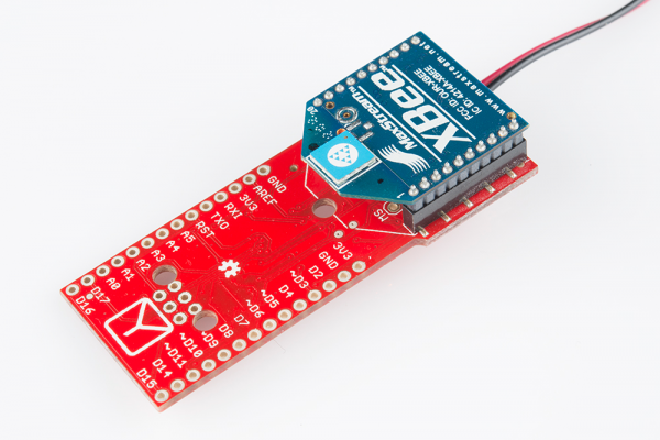
XBee’s are controlled and configured over a serial interface. To learn more about using XBee’s check out their datasheet and various tutorials for help getting started with these awesomely simple wireless transceivers.
Installing: Windows
Getting the Pro Micro or Fio v3 set up on your computer and in your Arduino environment can be difficult. Follow along on this page for a step-by-step guide through the driver installation and Arduino-enabling process.
Windows Driver Installation
Step 1: Download the Driver
Before plugging your board in, get a head start by downloading the drivers. Check the GitHub Repository for the latest files. The same driver file works for both the Pro Micro and the Fio v3. The drivers for both the Fio and the Pro Micro are signed for Windows users. You can download them directly using the link below.
Unzip that zip file, and don’t forget where you’ve left its contents. In that zip file, you should find the .inf and .cat files, which contains all the information Windows needs to install the Pro Micro’s driver. The sparkfun.inf driver and sparkfun.cat digitally signed catalog file will be found in . Arduino_Boards-master/sparkfun/avr/signed_driver .
Step 2: Plug in the Pro Micro / Fio v3
When you initially plug the board in, an «Installing device driver software» bubble notification should pop up in the lower-right corner of your taskbar. After the green dot circles the grey box a number of times, you’ll probably get a sad bubble like this:
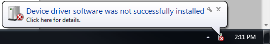
Never fear! Windows just doesn’t know where to find our driver.
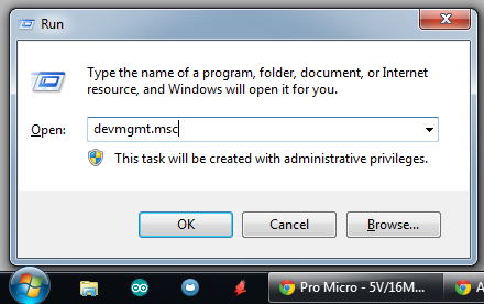
Step 3: Open the Device Manager
From here, the most straightforward way to install the driver is through the Device Manager. To get to the Device Manager, click the Start button, then open the Control Panel. In the Control Panel, click System and Maintenance, and then open the Device Manager.
Alternatively, you can open the Run prompt (Windows key+R) and type ‘devmgmt.msc’ and click OK.
In the Device Manager, expand the ‘Other devices’ tree, where you should find a ‘USB IO Board’ with a yellow warning sign over its icon. Right-click the ‘USB IO Board’ and select Update Driver Software. .
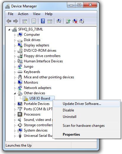
This should spawn an ‘Update Driver Software — USB IO Board’ window.
Step 4: Finding the Driver
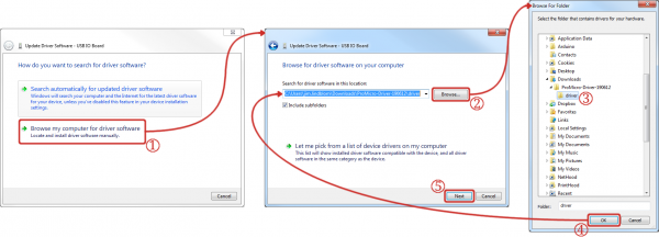
In the first window that pops up, click ‘Browse my computer for driver software’. On the next window, click ‘Browse. ‘ to search for the driver you just downloaded. It should be a folder named ‘Arduino_Boards-master’, in a subdirectory noted in step 1. After you’ve selected the ‘driver’ folder, click OK, then select Next.
Windows will attempt to do its driver install thing, but not before complaining about the driver being unsigned. It’s safe to select ‘Install this driver software anyway’ on the warning dialog.
After watching the progress bar beam by a few times, you should get a happy ‘Windows has successfully updated your driver software’ window. And the ‘Device Manager’ should have a new entry for the ‘SparkFun Pro Micro (COM ##)’ (or ‘SparkFun Fio V3 (COM##)’ if you have one of those) under the ‘Ports’ tree.
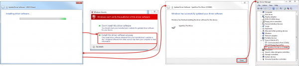
Take note of which COM port your Pro Micro was assigned. We’ll need it soon.
Installing the Arduino Addon
We’re still not completely ready for Arduino, but this is the final stretch. Before you can use the ProMicro in the Arduino IDE, you’ll need to install the board (.brd) files for the Fio/Pro Micro so the Arduino IDE will know how to communicate with your board.
Using the Board Manager
With the release of Arduino 1.6.4, adding third party boards to the Arduino IDE is easily achieved through the board manager. If you’re running an older version of Arduino (1.6.3 or earlier), we recommend upgrading now. As always, you can download the latest version of Arduino from arduino.cc.
To begin, you’ll need to point the Arduino IDE board manager to a custom URL. Open up Arduino, then go to the Preferences (File > Preferences). Then, towards the bottom of the window, paste this URL into the «Additional Board Manager URLs» text box:
You can add multiple URLs by clicking the window icon, and pasting in one URL per line.
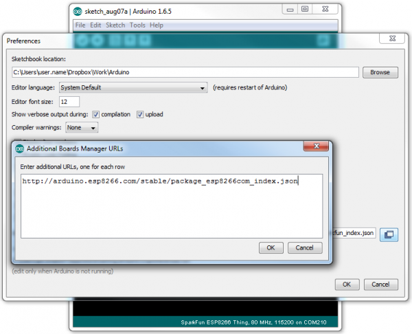
Click OK. Then open the Board Manager by clicking Tools, then hovering over the Board selection tab and clicking Board Manager.
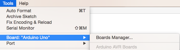
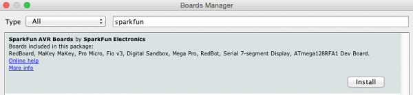
Search for ‘sparkfun’ in the Board Manager. You should see the SparkFun AVR Boards package appear. Click install, wait a few moments, and all the .brd files you’ll need should be installed, indicated by the blue ‘Installed’ that is printed next to the package.
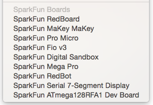
You should now be able to upload code to a number of SparkFun Arduino-compatible products, including the Fio and the Pro Micro.
Installing the .brd Files Manually
If you are using an older version of the Arduino IDE and do not have access to the Board Manager, then you’ll need to install the .brd files the old fashioned way.
To begin, download this zip folder, and unzip its contents into a ‘hardware’ directory within your Arduino sketchbook.
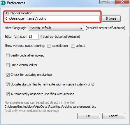
Where’s your Arduino sketchbook? Well, by default, it should an ‘Arduino’ folder in your home directory, but to double check you can go to ‘File’ > ‘Preferences’ within Arduino and check the ‘Sketchbook location’ text box. Just make sure you close all Arduino windows once you’re done.
Once you’ve unzipped that folder into the ‘hardware’ folder within your Arduino sketchbook (you may actually have to create a hardware folder), your directory structure should look something like this:
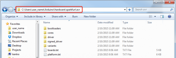
The structure of this directory is critical — it should look something like «Arduino/hardware/[manufacturer]/[architecture]», in this case [manufacturer] is «sparkfun», and [architecture] is «avr.»
There’s a lot going on in that addon, but one of the most important files is ‘boards.txt‘, which will add a few new entries to your ‘Tools > Board‘ menu.
To double-check that the board definitions have been added to Arduino, open up Arduino, and check under the ‘Tools > Board‘ menu. There should be some new entires for ‘SparkFun Pro Micro’, ‘SparkFun FioV3’, ‘Qduino Mini’, and other 32U4-based boards.
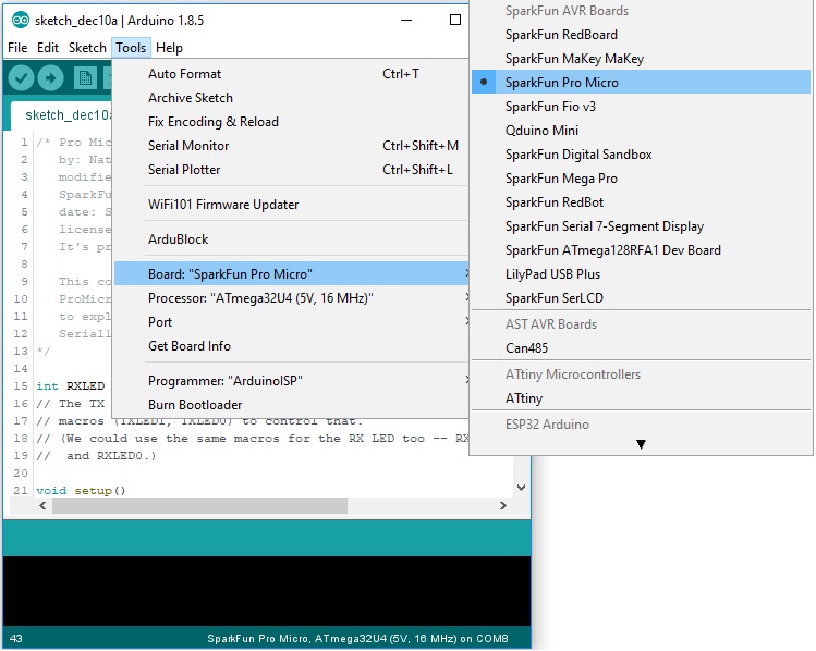
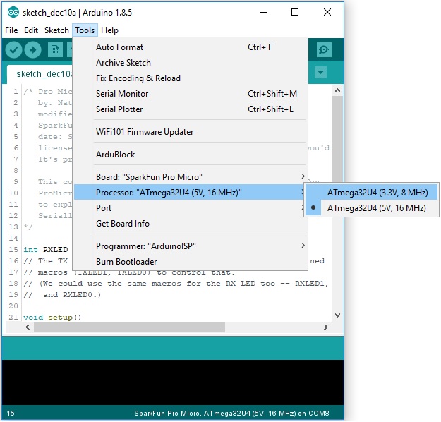
Notice there are two options for the Pro Micro — 8MHz and 16MHz. It’s very important that you select the Pro Micro option that matches your board’s voltage and speed. This should be listed under the Tools> Processor. Don’t know which board you have? Check the bottom of the board, where you should find either a ‘5V’ or ‘3.3V’ box checked.
You should also see your Pro Micro’s COM port under the ‘Tools > Serial Port‘ menu. Select it, and head over to the Example 1 page where we’ll upload our first piece of code.
Installing: Mac & Linux
If you’re using Mac or Linux, follow the steps below to get your Pro Micro (or Fio v3) ready to go on your computer. We’re not going to name names here, but installing the Pro Micro on Mac OS X and Linux is a lot easier than on other OS’s.
Following these directions is critical to getting your Pro Micro supported within your Arduino environment!
Board Installation
Using the Board Manager
With the release of Arduino 1.6.4, adding third party boards to the Arduino IDE is easily achieved through the board manager. If you’re running an older version of Arduino (1.6.3 or earlier), we recommend upgrading now. As always, you can download the latest version of Arduino from arduino.cc.
To begin, you’ll need to point the Arduino IDE board manager to a custom URL. Open up Arduino, then go to the Preferences (File > Preferences). Then, towards the bottom of the window, paste this URL into the «Additional Board Manager URLs» text box:
You can add multiple URLs by clicking the window icon, and pasting in one URL per line.
Click OK. Then open the Board Manager by clicking Tools, then hovering over the Board selection tab and clicking Board Manager.
Search for ‘sparkfun’ in the Board Manager. You should see the SparkFun AVR Boards package appear. Click install, wait a few moments, and all the .brd files you’ll need should be installed, indicated by the blue ‘Installed’ that is printed next to the package.
You should now be able to upload code to a number of SparkFun Arduino-compatible products, including the Fio and the Pro Micro.
Installing the .brd Files Manually
If you are using an older version of the Arduino IDE and do not have access to the Board Manager, then you’ll need to install the .brd files the old fashioned way.
When you initially plug your Pro Micro into a Mac, it’ll pop up a «Keyboard Setup Assistant» window. This stems from the Pro Micro’s ability to emulate an HID USB device (e.g. keyboards and mice) — the Mac thinks your Pro Micro is a human input device (which it could be! but isn’t yet).
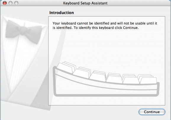
There’s nothing to configure in this window, so just click the big, red, ‘X’ to close it.
That’s all there is to it! The CDC (communication device class) portion of your Pro Micro (the part that handles USB to Serial conversion) should automatically install on your computer.
Installing the Arduino Addon
In order to use the Pro Micro or Fio v3 in your Arduino IDE, you need to add a few board definition files to it. That’s what we’ll do in this section. Begin by downloading the Pro Micro addon files.
With that downloaded, follow these steps to enable the Pro Micro in your Arduino environment:
- The addon files are supplied in a zip folder, so you’ll need to extract the files within first.
- Find your Arduino sketchbook folder. If you don’t know where it is, you can locate your sketchbook by looking at the preferences dialog in your Arduino IDE.
- If there isn’t already one, create a folder in your sketchbook called ‘hardware‘.
- Copy the ‘sparkfun’ folder that was unzipped in the first step into the ‘hardware‘ folder.
- Your directory structure should look something like «. /Arduino/hardware/sparkfun/avr.»
- Restart Arduino, and look under the Tools >Board menu. You should see a few new options, including SparkFun Pro Micro, SparkFun Fio V3, and Qduino Mini.
If the boards are visible, select the option that matches your board. If you have a Pro Micro, make sure you select the correct operating speed and voltage under Tools > Processor! At this point, select the COM port that the Pro Micro/FioV3/Qduino enumerated on. Then head over to the next page where we’ll upload our first sketch!
Example 1: Blinkies!
The Arduino-standard Blink sketch won’t have any visible effect on the Pro Micro — there’s no LED on pin 13. In fact, the only LEDs on the board are the power indicator, and RX/TX blinkies. Unlike other Arduino boards, though, we can control the RX/TX LEDs in our sketch. So let’s get blinking!
Upload the RX/TX Blinky, Hello World Sketch
Copy and paste the code below into the Arduino IDE. Make sure to select the correct board and COM port that your respective board enumerated to. Finally, upload [1] it to your Pro Micro
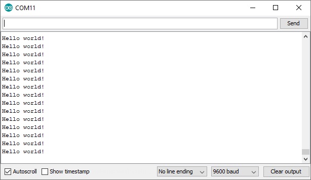
With the code uploaded you should see the RX and TX LEDs take turns blinking on and off every second. You can also open up the Arduino IDE’s serial monitor (set to 9600 bps) and see every programmer’s favorite two-word phrase.
Understanding the Sketch
RX LED
The RX LED is tied to Arduino’s pin 17. You can control it just as you would any other digital pin. Set it as an OUTPUT , and digitalWrite([pin], [level]) it HIGH to turn the LED off or LOW to turn the LED on. Here’s part of the code highlighted.
TX LED
The TX LED was not provided as an Arduino-defined pin, unfortunately, so you’ll have to use a pair of macros to control it. TXLED1 turns the LED on, and TXLED0 turns the LED off. Here’s part of the code highlighted.
Serial Monitor ( Serial ) and Hardware Serial UART ( Serial1 )
In that sketch, you’ll also notice a pair of Serial initialization statements:
That » 1 » makes a huge difference. Think of the Pro Micro having two separate serial ports. The one without the » 1 » is for communication to and from the computer over USB; this is what is visible in the Serial Monitor. The Serial1 port is a bonafide, hardware UART, where your Pro Micro can talk to any serial-enabled piece of hardware.
If you open up the Serial Monitor, you should only see Hello world! printed. ‘ Hello! Can anybody hear me? ‘ is being sent out over the hardware UART, where, presumably, nothing is listening. This begs the age-old question: «If a Pro Micro is saying ‘Hello!’ over the hardware serial port, and nothing is there to hear it, does the Pro Micro really say anything at all?»
Why Does My Board Re-Enumerate Every Upload?
In order to communicate serially, the Pro Micro emulates a virtual serial port. Actually, it emulates two different serial ports — one for the bootloader, and one for the sketch. Since the bootloader and sketch run individually. Only one of these serial ports is visible at any one time.
When you click ‘Upload’ in the Arduino IDE, the Pro Micro resets itself and starts its bootloader program. (The bootloader is a low-level program on the Pro Micro which enables self-programming via serial.) To our operating system, the bootloader looks like a completely different device, so it gets its own serial port number. While the Pro Micro is being programmed, the bootloader serial port will be open. When the sketch upload is finished, the bootloader will exit, that serial port will be closed, and the regular Pro Micro serial port will open up.
What this all boils down to is the fact that you have to be patient with Pro Micros. Every time you upload a new sketch, your OS will need to work its driver magic before you can open up the COM port. This can take a few seconds after the code has finished uploading.
[1] Note for Windows users: The first time you upload a sketch, it may fail and give you an error. On top of that Windows will pop up that familiar ‘Device driver software was not successfully installed’ notification. Don’t let this worry you too much. If you get the error, wait about a minute, and try uploading again.
Hopefully the upload will succeed the second time, but if it continues to fail, check out the how to enter the bootloader section of the FAQ. Windows needs to install the same driver we’ve already installed for the Pro Micro’s bootloader, but it’s unable to get everything set up before the bootloader exits.
Example 2: HID Mouse and Keyboard
By far, the Pro Micro’s most revolutionary feature (as far as Arduinos go) is its true USB functionality. The Pro Micro can be programmed to emulate any USB device you could imagine. You can even program it to act just like a mouse, keyboard, or other HID-class USB device.
What is HID?
It’s one of the many defined USB device classes. Every USB device is assigned a class, which defines what its general purpose is. There are loads of classes — printers, hubs, speakers, and webcams to mention a few, but in this example we’ll be emulating HID — Human Interface Device. The ATmega32U4 takes care of the USB-hardware hurdle, but we’ve still got to clear the firmware one. Time for some example code! We broke up the HID example into two parts.
Example 2a: USB Keyboards Made Simple
To emulate a USB keyboard, we’ll be making use of the Keyboard class. Here are some of the functions made available to us by this class:
Keyboard.write(char) — This function will send a single character over USB. The character passed can be any standard, printable, ASCII-defined character: 0-9, a-z, A-Z, space, symbols, etc. Here’s an example line of code:
Keyboard.print(string) — If you need to perform a series a Keyboard.write() ‘s, consider using just a single Keyboard.print() . This works similar to Serial.print() – give it a string of characters and it’ll send that stream of characters over USB. Keyboard.println(string) is also defined, if you want a newline/linefeed to close out your string. An example:
Keyboard.press(byte) and Keyboard.release(byte) give you more precise control over key presses. They do exactly what you’d expect. One presses a button down, the other releases a button. Make sure you release any buttons you press, otherwise you’ll encounter some wiggyness on your computer.
That’s it. You don’t need to include any libraries or anything, just invoke any of those functions. Here’s an example sketch to try it out:
In this sketch, connecting pin 9 to ground will make the Pro Micro spit out a ‘ z ‘ character. If you have a simple, momentary button handy, tie one end to pin 9 and the other to ground. Otherwise, just use a wire to short 9 to GND.
After a Keyboard.write() or Keyboard.print() function has been performed by the Pro Micro, your computer will have to decide what to do with it. What your computer does with that character, or string of characters, is entirely dependent on what program it’s running at the time. If you have a text editor open and active, it’ll print it out there. Or you can try using the textbox below to test.
Example 2b: USB Mouse Functionality
That covers about half of USB HID library. How about we add a mouse to the mix now? Implementing a USB HID mouse requires a few more functions, but it’s still crazy simple. There are five functions provided by Arduino’s HID class that can be used to implement a mouse:
- Mouse.move(x, y, wheel) tells the computer to move the mouse a certain number of pixels along either the x, y and/or wheel axis. Each variable can be any value between -128 and +127, with negative numbers moving the cursor down/left, positive numbers move the right/up.
- Mouse.press(b) sends a down-click on a button or buttons. The button(s) will remain «pressed» until you call Mouse.release(b) . The b variable is a single byte, each bit of which represents a different button. You can set it equal to any of the following, or OR (|) them together to click multiple buttons at once:
- MOUSE_LEFT — Left mouse button
- MOUSE_RIGHT — Right mouse button
- MOUSE_MIDDLE — Middle mouse button
- MOUSE_ALL — All three mouse buttons
Mouse.click(b) sends a down-click (press) followed immediately by an up-click (release) on button(s) b . For example, to click the left and right buttons simultaneously, try this:
Here’s some example code to show off these functions:
This sketch is set up so that an analog joystick connected to analog pins A0 and A1 can be used to move your mouse cursor.
The loop() of this code continuously monitors the horizontal and vertical analog values of the joystick and sends the Mouse.move() command based on what it reads. It’ll move the mouse in steps, depending on what the sensitivity variable is set to. With sensitivity set to 2, the cursor will move in either 1 or 2 pixel steps. Depending on the orientation of the joystick, there is also an option to invert the mouse based on how the «V» is pointing by adjusting invertMouse .
The select switch on the joystick is used to control the mouse left click. Notice this code is using Mouse.press() and Mouse.release() , rather than just calling a single Mouse.click() . This requires a bit more coding, but it allows you to do things like drag-and-drop, double click, etc.
For more HID example code, check out the Arduino-supplied examples under the File > Examples > 09.USB menu. Or check out Arduino’s reference language under USB for more information.
Troubleshooting and FAQ
On this page you’ll find troubleshooting tips and FAQs. Here’s a directory of the subjects covered:
Serial Port Not Showing Up in ‘Tools > Board’ Menu
The Pro Micro can be a finicky little thing. There are a few series of events that can lead to its serial port being removed from the Arduino IDE’s Serial Port selection menu. If you can’t see your Pro Micro’s serial port, give these steps a try:
- Close all Arduino windows. (Don’t forget to save!)
- Unplug Pro Micro from your computer.
- Wait a few seconds for the device to be detached.
- Plug Pro Micro back in.
- Open Arduino back up, check the Serial Ports menu again.
Reset to Bootloader
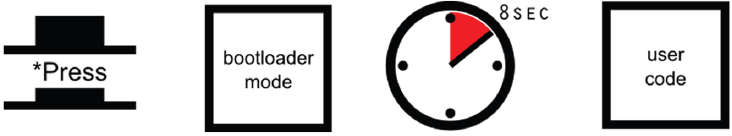
We ship the Pro Micro with a modified version of the Arduino Leonardo bootloader, with one major enhancement. When a Leonardo (or any device using the «stock» bootloader) is externally reset, it goes back into the bootloader. and waits there eight seconds before it starts running the sketch. For some embedded projects, waiting eight seconds before a program runs isn’t acceptable, so we modified the bootloader run time.
 |  |
| Arduino Leonardo | Leonardo bootloader on reset functionality. |
When a Pro Micro is externally reset (by pulling the RST pin low), it’ll only briefly ( Serial Port‘ menu to the bootloader COM port. Quick! You’ve only got eight seconds. On Windows, the bootloader’s COM port number is usually one number higher than the Pro Micro’s regular port number.
With the serial port set, we’re just about ready to re-upload our sketch. But first, double check that the board is correctly set. Then reset to bootloader again, and quickly upload your sketch. Again, you’ll have to be quick. you’ve only got eight seconds. It may help to press the Upload keybind — CTRL + U / CMD + U — immediately after resetting.
It can take a few tries to get the timing right. Since the code has to compile first, it may help to hit upload first and then reset.
Still having trouble getting that timing down?
One of our customers (shout out to RichardDL) has come up with a nifty solution (Windows only) to automate the bootloader process and program the board, by creating a batch file. Check out the details in his forum post!
Code Runs After Upload But Fails to Start After Power Cycle
We found that an ATmega32U4 (like the Pro Micro 3.3V/8MHz) can brown out when outputting power to a boost converter. While code can run after uploading, a power cycle from the initial current draw to a boost converter is enough to cause the Pro Micro brown out. Thus causing the sketch to not run. This requires the user to toggle the reset button after a power cycle.
Frequently Asked Questions
If you’re having technical difficulties with your Pro Micro or Fio v3, see if any of the answers to these FAQs help. If not, please get in touch with our tech support team.
What are VID and PIDs?
VID is short for ‘Vender Identification’ and PID is short for ‘Part Identification’. In other words, this pair of IDs defines the device. This is how your computer knows what you’ve plugged in, what drivers to use with it, what COM port is assigned to it, etc. All native USB devices have a VID/PID.
All SparkFun ATmega32U4 boards share the same VID — 0x1B4F, and they all have unique PIDs. 5V Pro Micros lay claim to PIDs 0x9205 and 0x9206 (one for the bootloader, one for the sketch). 3.3V Pro Micros will show up as 0x9203 and 0x9204 for bootloader and sketch, respectively. And the Fio v3 has 0xF100 and 0xF101.
How Can I Change the VID and PID on an ATMega32U4 Board?
Every time you upload code the VID and PID are uploaded to the device. These values are located in the ‘boards.txt‘ file and will therefore be determined by the board you have selected. Keep in mind that if you select the wrong board you will get the wrong VID/PID uploaded which means the computer can’t recognize, and program the board. The VID/PID for the bootloader is part of the bootloader file. To change this you will need to recompile the bootloader with the new VID/PID, and upload it.
Why Does my ATMega32U4 Board Show up Twice in Device Manager?
Both the bootloader and the sketch have their own VID/PIDs. When you plug in a board the bootloader starts running for a few seconds, and you will see the board show up in Device Manager based on those VID/PIDs. After a few seconds, the sketch will start running, and you will see Device Manager disconnect from the bootloader and connect to the sketch.
How Does the IDE Know Which COM Port to Use?
When the IDE resets the board, the COM port is disconnected from the computer. The IDE then looks for a new COM port. This is the port it uses. This is one of those weird things Arduino did to get things to work on this chip.
How Do I Reinstall the Bootloader?
Check out or reinstalling the bootloader tutorial, which should work for both ATMega32U4 and ATMega328 boards. If you have the tools to do so, reinstalling the bootloader is often easier then trying to stay in the bootloader. Since reinstalling the bootloader puts the board back in factory settings this will reset the VID/PID numbers allowing your board to work again.
Resources and Going Further
Thanks for checking out our Pro Micro and Fio v3 Hookup Guide! If you’re looking for more resources related to these boards, here are some links:
Thanks for reading along with our Pro Micro hookup guide! Hopefully now you’re fully prepared to begin using the Pro Micro in a project of your own. Here are some tutorials that might be worth checking out as you continue down the rabbit hole:


