- Connecting Sensors and Actuators
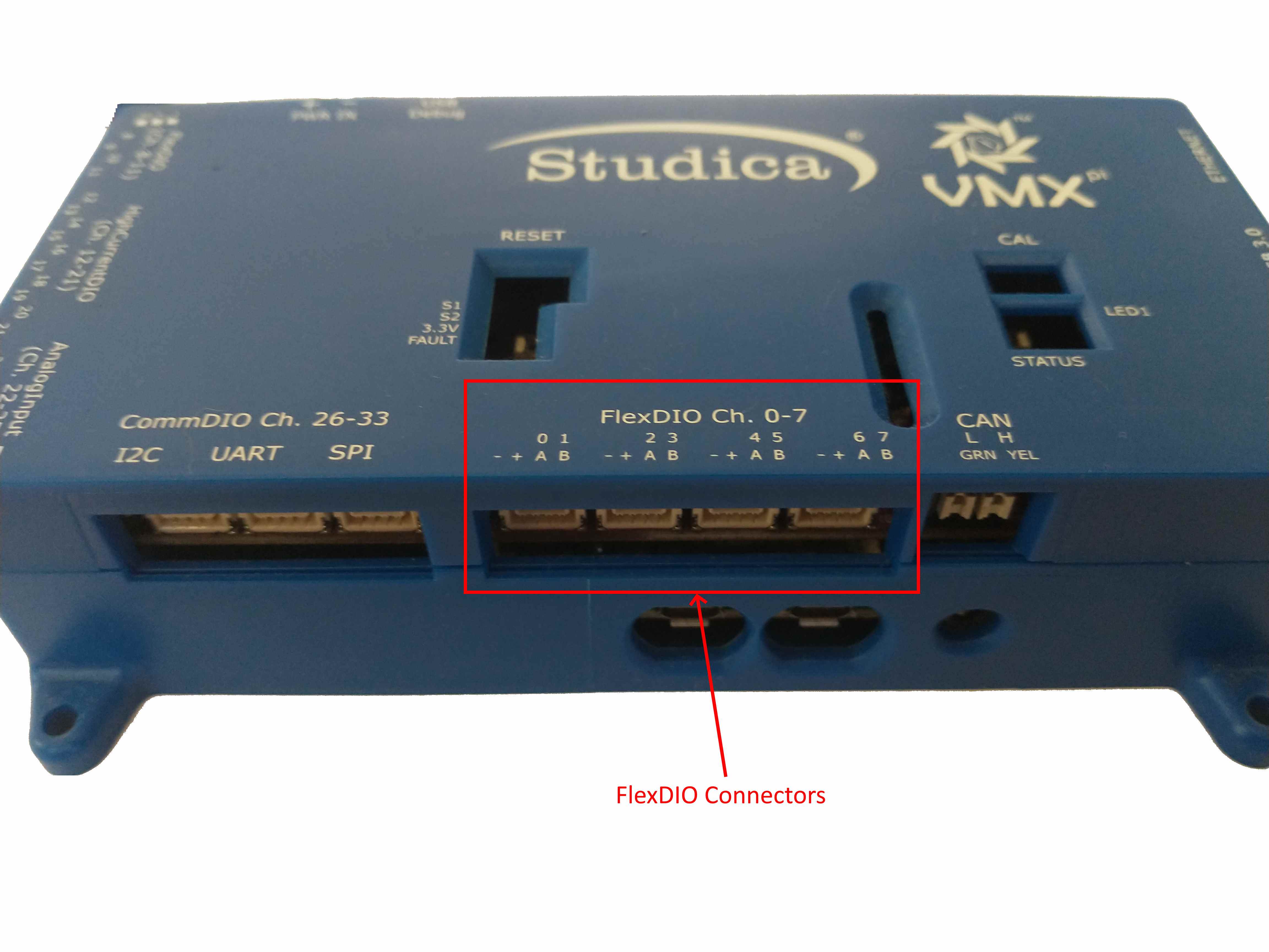
- FlexDIO Connectors
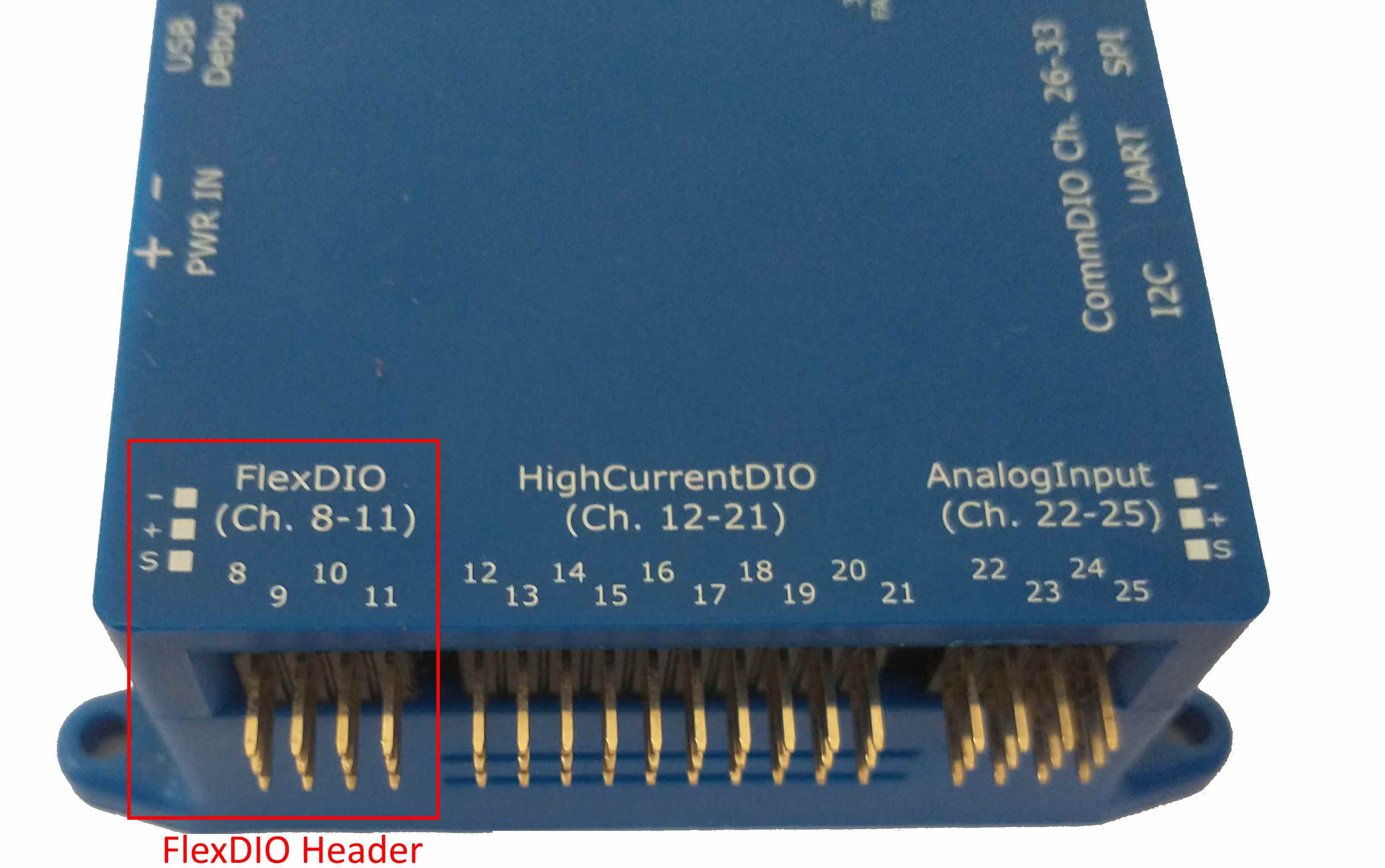
- FlexDIO Header
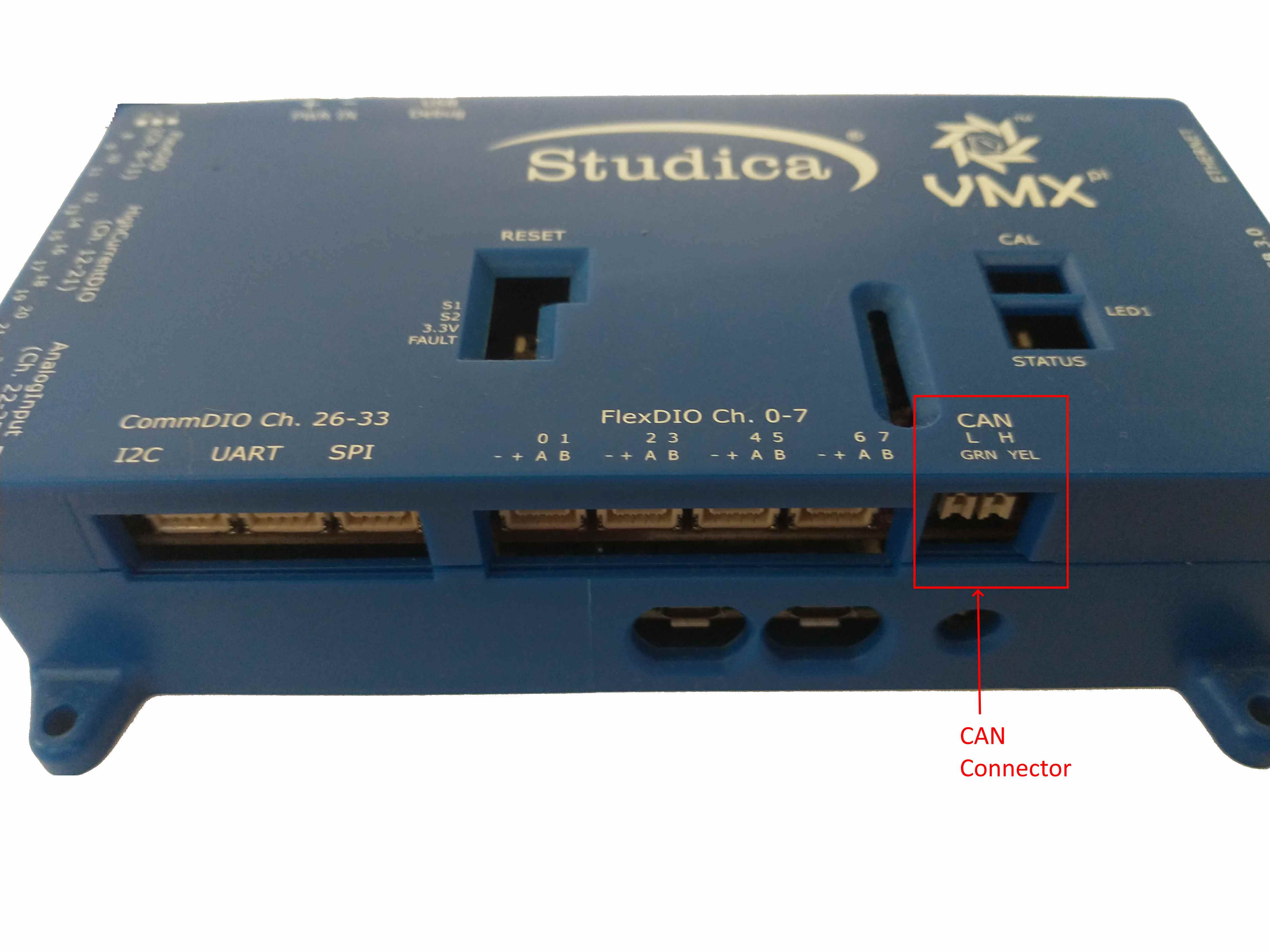
- CAN Connector
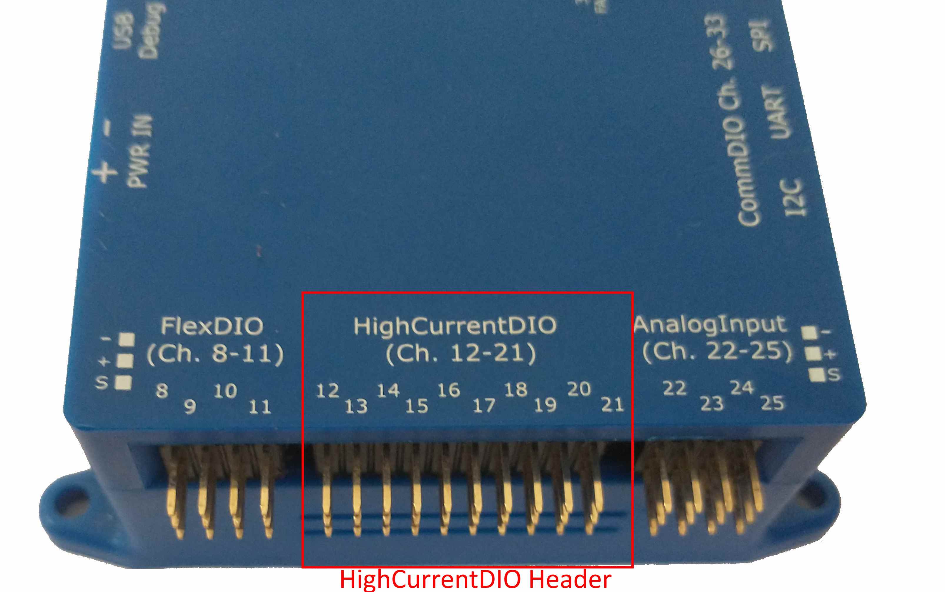
- High-Current DIO Header
- Analog Input Header
- CommDIO Connectors
- Output Voltage Selection
- High Current DIO Channel Direction configuration
- VMX Installation Instructions
- Software:
- — Raspberry Pi — Getting Started on Raspberry Pi
- — roboRIO
- — Windows
- Controllers
- Titan Quad Motor Controller
- VMX Robotics Controller
- myRIO with Studica Toolkit and 3 LabVIEW Licenses
- Blackhawk Robotics Expansion Board
- MD2 Motor Driver Adapter for NI myRIO
Connecting Sensors and Actuators
The VMX Robotics Controller provides a large number of electrical power and signal “pins” which connect to external devices including Sensors and Actuators.
This summary of VMX IO configuration is sufficient for most robot Programming uses; more detailed information is available in the Hardware Reference Manual.
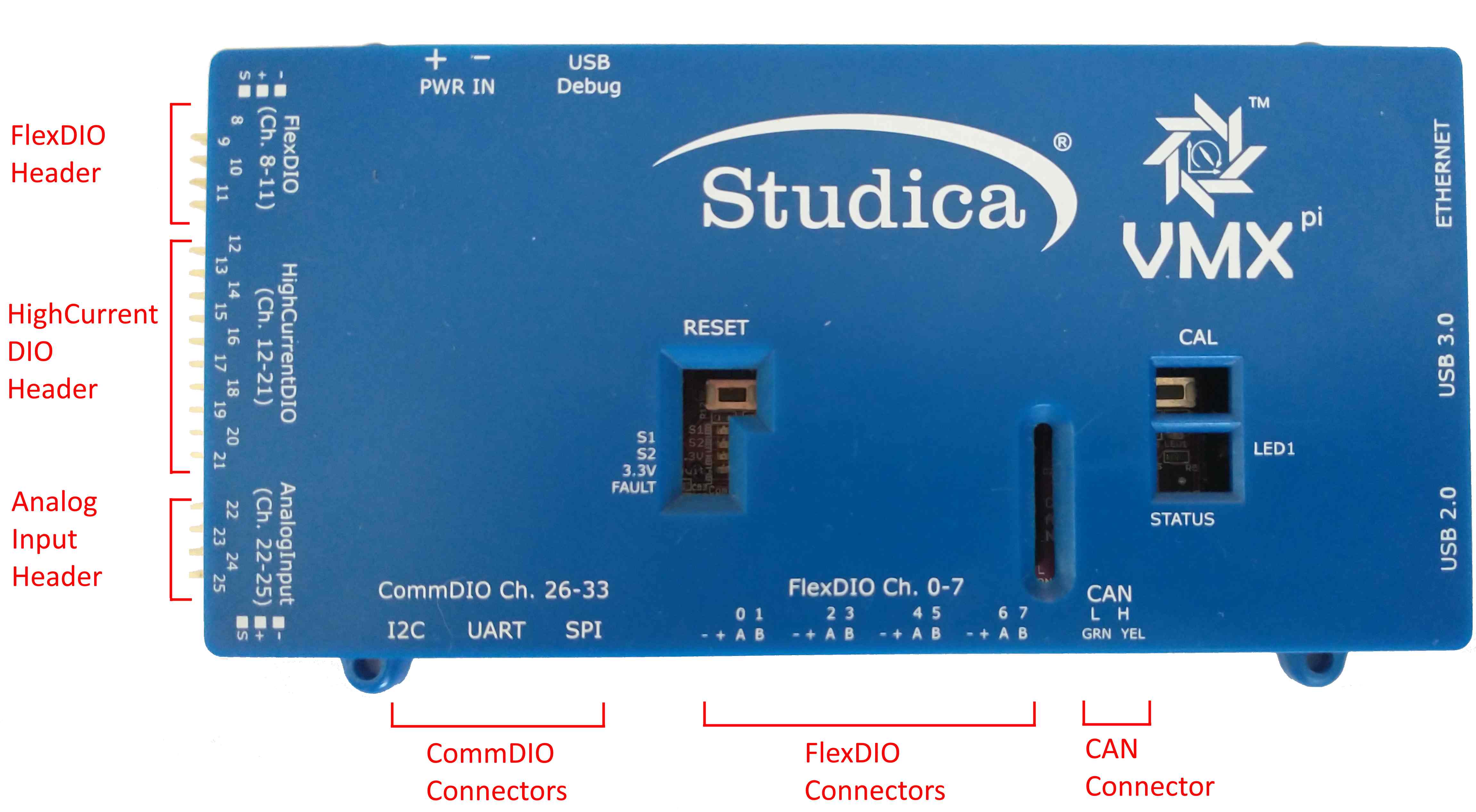
VMX Connector Blocks 
VMX provides several different Connector Blocks.
Location on VMX
Flex DIO Header
High Current DIO Header
Analog Input Header
Comm DIO Connectors
Flex DIO Connectors
Three (3) types of Connectors are used:
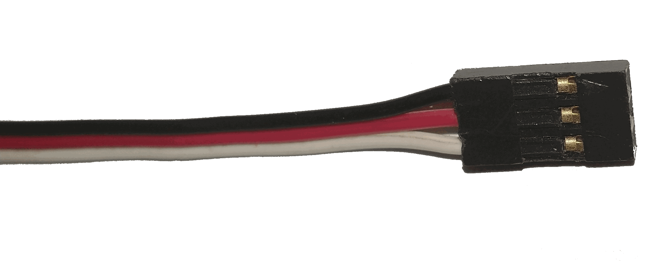
3-pin PWM-style Connector 
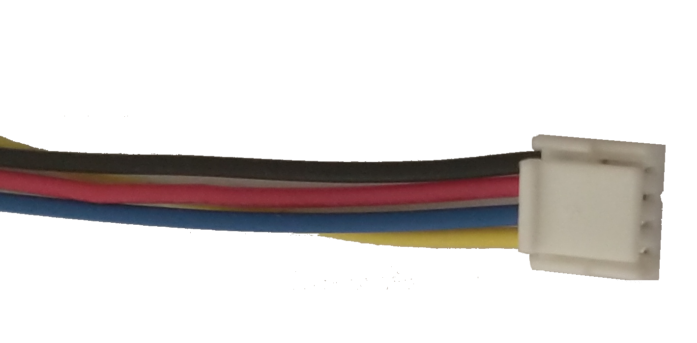
4-pin JST GH Connector 
FlexDIO Connectors
FlexDIO Connectors are a set of four locking JST GH connectors (4 pins each) with power, ground, signal A and signal B on each connector. These connectors are designed to support Quadrature Encoders, but may also be configured for use as Digital Inputs, Interrupts, Digital Outputs, PWM Generators or Counters.
FlexDIO Header
The FlexDIO Header provides 4 sets of power, ground, and a single signal channel. The signals may be configured to support Quadrature Encoders, Digital Inputs, Interrupts, Digital Outputs, PWM Generators or Counters. Note that only 2 of the pins on this header support Quadrature Encoders, see below for details.
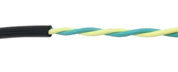
CAN Connector
The CAN Connector accepts a pair of wires (CANH and CANL signals) with bare ends, which connect to a CAN bus.
High-Current DIO Header
The High-Current DIO Header provides 10 sets of power, ground, and a single signal channel. The signals may be configured to support Digital Inputs, Interrupts, Digital Outputs, PWM Generators or Relays.
High-Current DIO Header 
The High-Current DIO Header may be configured in either Output or Input Direction, see below for details.
Analog Input Header
The Analog Input Header provides 4 sets of power, ground, and a single signal channel. The signals may be configured to support Analog Accumulation and/or Analog-triggered Interrupts.
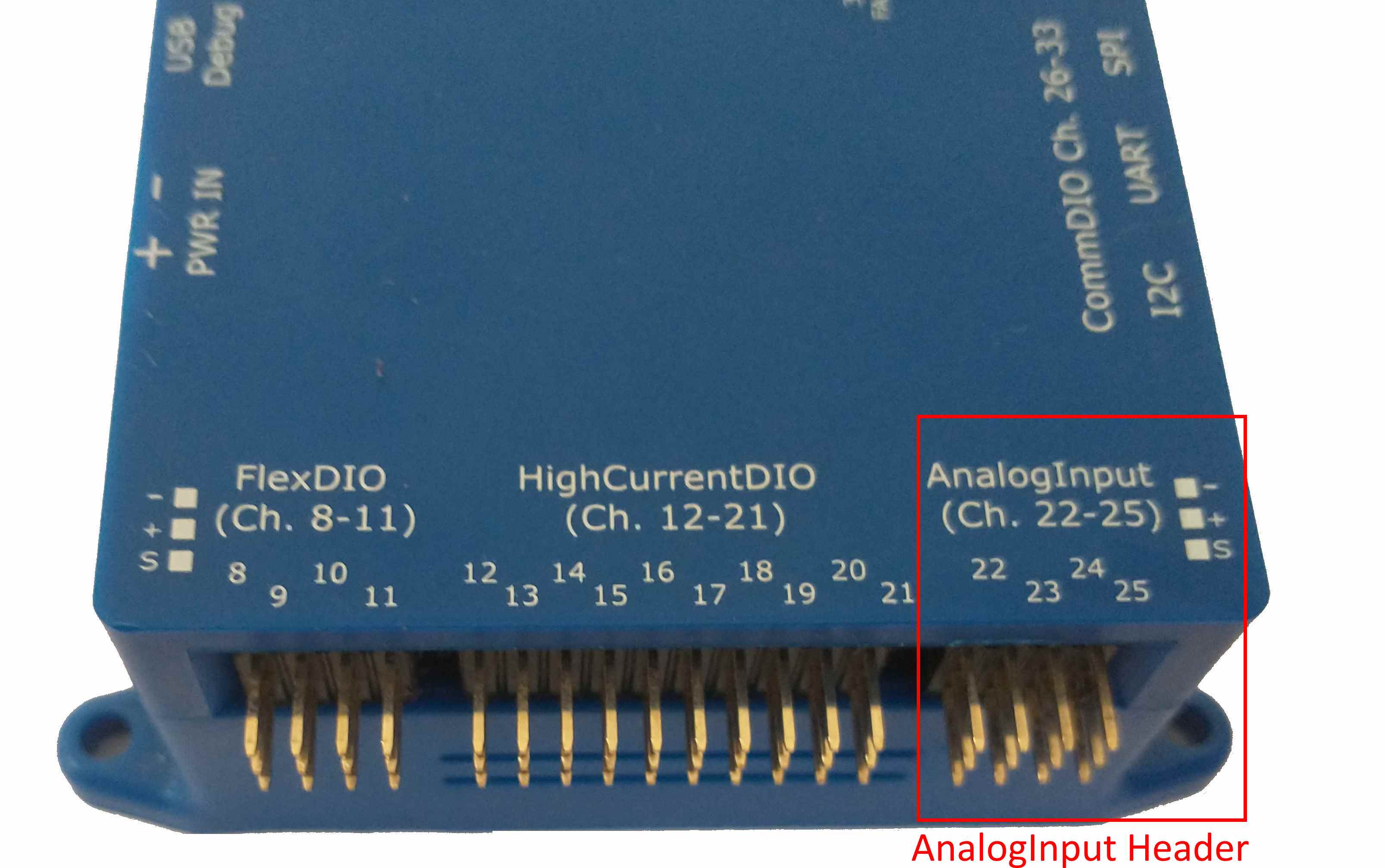
Analog Input Header 
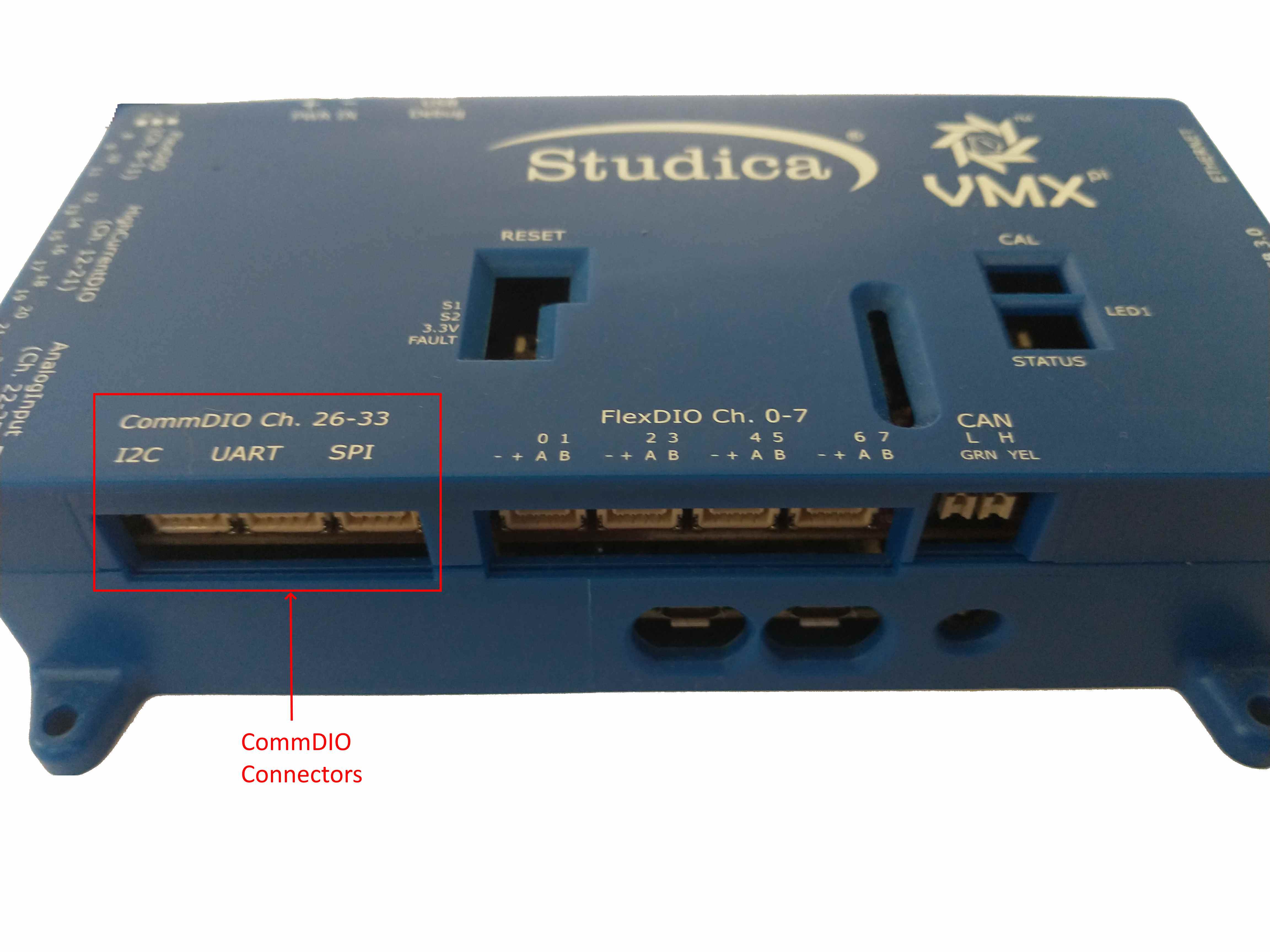
CommDIO Connectors
The three (3) CommDIO Connectors are three locking JST GH connectors (4 pins each) with different sets of power/ground/signals. Each connector may be configured to communicate using the corresponding digital communication protocol. Alternatively, the Input Channels may be configured for use as Digital Inputs or Interrupts; Output Channels may be configured for use as Digital Outputs or PWM.
Each of the four pins on each connector have a different definition, depending upon the type:
I/O Channel Type Pin 1
Unlike the I2C and TTL UART Connectors, the SPI connector has 4 signal pins and does not provide power and ground.
Output Voltage Selection
Either 5 or 3.3V power output for external devices (both power and signal level) may be selected for Flex, High Current and Comm DIOs and also for power pins on the Analog Input Header.
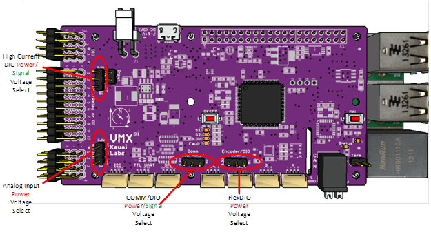
Output Voltage Selection Jumpers 
If any of the external devices connected to pins in any of these groups are not 5V tolerant, ensure the voltage selection jumper is set to 3.3V to avoid damage to the external device.
The Output Voltage Selection Jumper can only be accessed by opening the VMX enclosure.
High Current DIO Channel Direction configuration
The entire bank of High Current DIOs can be either all outputs (default), or all inputs. Direction selection is performed in hardware via the High Current DIO Input/Output Jumper. If the jumper is present, all High Current DIOs function as outputs, otherwise they function as inputs.
Output Configuration: 10 High Current DIO Pins are Digital Outputs Input Configuration: 10 High Current DIO Pins are Digital Inputs
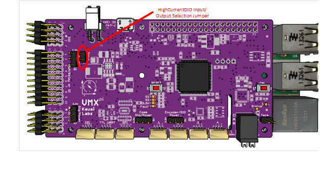
High Current DIO Channel Direction Jumper 
The High Current Direction setting impacts the behavior of PWM, Relay and Digital IO Channels, described further below. Therefore this setting is one of the first things to verify in case of improper operation of the High Current DIO Channels.
Use the default Direction (Output) unless your configuration requires more digital inputs.
The Output Voltage Selection Jumper can only be accessed by opening the VMX enclosure.
© Copyright 2021, Studica. Revision 0f0d45e7 .
Источник
VMX Installation Instructions
Plug-n-play: VMX is designed for rapid installation on a robot, making it easy to install and integrate onto robots including Raspberry Pi-based and FIRST FRC Robots.
Orientation: Tips and tricks for ensuring VMX measurements are aligned with your robot, including the Omnimount flexible mounting feature.
Enclosure: To protect an installed VMX, an enclosure is available – purchased separately
Guidance:
Installation:
Software:
— Raspberry Pi
— Getting Started on Raspberry Pi
— roboRIO
- Libraries for accessing VMX IMU data from a National Instruments RoboRIO®-based FRC Robot are now available.
- To access VMX from a FRC RoboRIO-based system, select the USB interface option available in the navX-MXP RoboRIO libraries.
- navX-MXP libraries for use with the RoboRIO Libraries from WPI are available in each of the languages/development environments commonly used to development FIRST FRC robot applications:
- Java
- C++
— Windows
VMX Tools for Windows provide several useful tools which help update VMX firmware, configure the real-time motion-processing algorithms, perform advanced calibration of the Magnetometer.
These tools are not required to use VMX, but can be useful in certain situations. We recommends all VMX customers install the VMX Tools for Windows.
navXUI
Additionally, VMX Tools for Windows includes the navXUI user interface application provides a simple way to visualize the data provided by VMX.
Configuration/Calibration Tools
VMX software includes several tools for magnetometer calibration and advanced configuration. These tools run on a Windows PC and communicate with VMX via USB.
NOTE: The Configuration/Calibration tools are provided for use by advanced users; please carefully read the tool descriptions before using them.
Installing/Running VXM-pi Tools for Windows
- Make sure Java 7 (version 1.7) or Java 8 (version 1.8) is installed on your computer. The 64-bit version of Java is recommended. To tell which version of java is currently “Active”, open up a command window, and type this command:
Источник
Controllers

Titan Quad Motor Controller
The Titan Quad Motor Controller is a powerful, 4-channel CAN-based motor controller with a built-in fuse-box (for DC motors up to 20A).
Features:
- 4 x Hardware encoder ports – one for each motor
- 2 limit switch ports for each motor
- Fuse box to set manual current limits
- 2x Power extension ports to power other 12VDC devices. I.E.
- VMX Robotics Controller
- Servo Power Module
- Built in LED Controller
- 6A power supply for LED’s
- i2c communication port to control LED Controller
- USB ports are updated to USB-C to better support todays cable standards
- Step File

VMX Robotics Controller
The Studica VMX is a powerful robot controller,
- Enables Tele-op and autonomous control
- Supports Java and C++, future support for ROS
- Integrates the navX-IMU, a Linux based controller, Gigabit Ethernet, USB3 ports and built-in Wifi/Bluetooth.
- Can be used an a Robot Control System or Vision/Motion processor
- Supports Open CV, Tensor Flow, SLAM (Simultaneous Localization and Mapping
- Step File
The Studica VMX leverages five recent key technology developments,
- Highly-integrated, inexpensive, WiFi-enabled, multi-core Linux computing platform with lots of USB IO for expansion
- 32-bit ARM Microcontrollers incorporating sophisticated I/O and digital communications engines
- Low-cost MEMs Inertial Measurement Units (IMUs)
- Powerful software providing rich libraries and tools for developing robot software in C++, Java
- CAN bus for high-speed, real-time communication between devices
The Studica VMX Technology Enables,
- Far richer development environments and tools
- Because VMX is much more than a robot controller – it is a powerful, Linux-based desktop computing platform with network/monitor/keyboard/mouse support.
- Very powerful software features
- State-of-the-art software development GUIs (e.g., VS Code) libraries and tools (drive- train kinematics, path-planning, vision processing, autonomous navigation, performance data acquisition/playback)
- Access to cutting-edge sensors (for use outside the competition)
- VMX’s multitude of modern digital communications interfaces and Linux-based operating system allow users to directly access most modern devices (e.g., Intel RealSense tracking and depth cameras and LIDAR

myRIO with Studica Toolkit and 3 LabVIEW Licenses
Includes the Studica Toolkit and 3 classroom licenses of labVIEW, the NI myRIO, industry-standard reconfigurable I/O (RIO) technology, the enclosed version of myRIO (myRIO-1900) places three I/O connectors, wireless capabilities, a dual-core ARM real-time processor, and a customizable Xilinx FPGA. With its on board devices, seamless software experience, and library of course-ware and tutorials, myRIO provides a controller ideal for the WorldSkills Mobile Robotics Competition.
Includes Driver and Software DVD, USB cable, power supply with international accessory and MSP screw-terminal connector.
Note: This can only be purchased by educational institutions or students for use with the WorldSkills Mobile Robotics Competition.

Blackhawk Robotics Expansion Board
Studica Blackhawk Expansion Board is a programmable expansion add on for your WorldSkills Mobile Robot.The board is used with the Studica MD2 driver board and the NI myRIO to control servo motors and to add additional sensor expansion and I/O including limit switches and relays.
Note:
- Requires Studica MD2 Driver Board and NI myRIO with LabVIEW and StudicaToolkit
- Included with WorldSkills Mobile Robotics Collection or may be purchased as an upgrade for existing customers with Collection 2017 or 2018 and MD2.
The Studica WSR Robotic Expansion Board features:
- 5V — 3A Servo power that supports to 2 additional servos
- 5V — 5A additional power output
- 5V and 12V FPV camera power
- Dedicated myRIO and Radio power ports to power both devices easily
- 3 Digit Voltmeter to give the current battery voltage
- Reverse Voltage Protection
- 3 on board Relays, 1 of the Relays can be changed into a timed switch for an indicator light by flipping the switch next to the relay to enable the timer.
- Arduino like Microcontroller on board to give sensor feedback to the myRIO
- 4 Sharp Sensor ports
- 2 Studica Line Follower Sensor ports
- 16 Pulled high Limit Switch ports
- Arduino 1.0 Header
- Superfast 84 MHz speed
- Dedicated I2C header to plug directly into the I2C header of the MD2 board

MD2 Motor Driver Adapter for NI myRIO
The Studica MD2 is a next-generation high performance Motor Controller Driver and Sensor Adapter with many added features to make it ready to use in your robot project. The included VNH5019ATR-E Motor Controller ICs are very robust with high current output and several important protection features. Many other I/O options have been incorporated into this design to make it extremely easy to interface to several different sensors.
Features,
- Includes 2 VNH5019 Motor Controller ICs,
- 2 Enable Inputs, 2 direction inputs, one PWM input per channel up to 20Khz
- Up to 12A Continuous output per channel, 30A peak current short ms duration
- Under-voltage, over-voltage, reverse-voltage protection
- Thermal Shutdown protection
- Current Limit protection
- Current Sense Output Proportional to Motor Current (approx. 140 mV/A)
- Loss of Ground and Loss of Vcc Protection
- Protection against short to Ground and short to Vcc
Specifications,
- 3V-compatible inputs
- Directly interfaces with myRIO MXP Port
- 8-16V DC Battery Input Terminal, J7, (GND, MTRS+ PWR)
- Jumper Selectable Current sense feedback from the VNH5019 Motor ICs, J12, J17
- Reverse Power LED Indicator
- FWD and REV Motor Direction LED Indicators
- 3 Servo Headers, J9, J10, J11, (SIG, SVDC, GND)
- 1 Parallax Ping Sensor Port, J13, (GND, VCC, DIO)
- 1 Sharp IR Port, J21, (AI0, VCC, GND)
- 1 LSB Port, J18, (VCC AI0, AI1, AI2, AI3, GND)
- 1 NavX Port, J19, (VCC, SDA, SCL, GND)
- 2 Encoder Ports, J22, J23, (VCC, ENCB, GND, ENCA)
- 1 I2C Port, J20, (NC, SCL, SDA)
- Built in 5V 3A voltage Regulator
- 3.3V Power Rail Header, J3, from myRIO
- 5V Power Rail Header, J4, from onboard regulator
- GND Rail Header, J6
- Separate Servo Power Input, J8 (SV+ PWR, GND)
Источник


