- Architecture
- Design principles
- Switch tagging protocols
- Master network devices
- Networking stack hooks
- The Linux Kernel documentation
- Licensing documentation
- User-oriented documentation
- Firmware-related documentation
- Application-developer documentation
- Introduction to kernel development
- Kernel API documentation
- Conceptual Architecture of the Linux Kernel
- Ivan Bowman January 1998 For Ric Holt CS746G Assignment One
- Abstract
- Contents
- List of Figures
- 1. Introduction
- 1.1 Purpose
- 1.2 Challenges of this Paper
- 1.3 Organization
- 2. System Architecture
- 2.1 System Overview
- 2.2 Purpose of the Kernel
- 2.3 Overview of the Kernel Structure
- 2.4 Supporting Multiple Developers
- 2.5 System Data Structures
- 2.5.1 Task List
- 2.5.2 Memory Map
- 2.5.3 I-nodes
- 2.5.4 Data Connection
- 3. Subsystem Architectures
- 3.1 Process Scheduler Architecture
- 3.1.1 Goals
- 3.1.2 Modules
- 3.1.3 Data Representation
- 3.1.4 Dependencies, Data Flow, and Control Flow
- 3.2 Memory Manager Architecture
- 3.2.1 Goals
- 3.2.2 Modules
- 3.2.3 Data Representation
- 3.2.4 Data Flow, Control Flow, and Dependencies
- 3.3 Virtual File System Architecture
- 3.3.1 Goals
- 3.3.2 Modules
- 3.3.3 Data Representation
- 3.3.4 Data Flow, Control Flow, and Dependencies
- 3.4 Network Interface Architecture
- 3.4.1 Goals
- 3.4.2 Modules
- 3.4.3 Data Representation
- 3.4.4 Data Flow, Control Flow, and Dependencies
- 3.5 Inter-Process Communication Architecture
- 4. Conclusions
Architecture
This document describes the Distributed Switch Architecture (DSA) subsystem design principles, limitations, interactions with other subsystems, and how to develop drivers for this subsystem as well as a TODO for developers interested in joining the effort.
Design principles
The Distributed Switch Architecture is a subsystem which was primarily designed to support Marvell Ethernet switches (MV88E6xxx, a.k.a Linkstreet product line) using Linux, but has since evolved to support other vendors as well.
The original philosophy behind this design was to be able to use unmodified Linux tools such as bridge, iproute2, ifconfig to work transparently whether they configured/queried a switch port network device or a regular network device.
An Ethernet switch is typically comprised of multiple front-panel ports, and one or more CPU or management port. The DSA subsystem currently relies on the presence of a management port connected to an Ethernet controller capable of receiving Ethernet frames from the switch. This is a very common setup for all kinds of Ethernet switches found in Small Home and Office products: routers, gateways, or even top-of-the rack switches. This host Ethernet controller will be later referred to as “master” and “cpu” in DSA terminology and code.
The D in DSA stands for Distributed, because the subsystem has been designed with the ability to configure and manage cascaded switches on top of each other using upstream and downstream Ethernet links between switches. These specific ports are referred to as “dsa” ports in DSA terminology and code. A collection of multiple switches connected to each other is called a “switch tree”.
For each front-panel port, DSA will create specialized network devices which are used as controlling and data-flowing endpoints for use by the Linux networking stack. These specialized network interfaces are referred to as “slave” network interfaces in DSA terminology and code.
The ideal case for using DSA is when an Ethernet switch supports a “switch tag” which is a hardware feature making the switch insert a specific tag for each Ethernet frames it received to/from specific ports to help the management interface figure out:
what port is this frame coming from
what was the reason why this frame got forwarded
how to send CPU originated traffic to specific ports
The subsystem does support switches not capable of inserting/stripping tags, but the features might be slightly limited in that case (traffic separation relies on Port-based VLAN IDs).
Note that DSA does not currently create network interfaces for the “cpu” and “dsa” ports because:
the “cpu” port is the Ethernet switch facing side of the management controller, and as such, would create a duplication of feature, since you would get two interfaces for the same conduit: master netdev, and “cpu” netdev
the “dsa” port(s) are just conduits between two or more switches, and as such cannot really be used as proper network interfaces either, only the downstream, or the top-most upstream interface makes sense with that model
Switch tagging protocols
DSA supports many vendor-specific tagging protocols, one software-defined tagging protocol, and a tag-less mode as well ( DSA_TAG_PROTO_NONE ).
The exact format of the tag protocol is vendor specific, but in general, they all contain something which:
identifies which port the Ethernet frame came from/should be sent to
provides a reason why this frame was forwarded to the management interface
All tagging protocols are in net/dsa/tag_*.c files and implement the methods of the struct dsa_device_ops structure, which are detailed below.
Tagging protocols generally fall in one of three categories:
The switch-specific frame header is located before the Ethernet header, shifting to the right (from the perspective of the DSA master’s frame parser) the MAC DA, MAC SA, EtherType and the entire L2 payload.
The switch-specific frame header is located before the EtherType, keeping the MAC DA and MAC SA in place from the DSA master’s perspective, but shifting the вЂreal’ EtherType and L2 payload to the right.
The switch-specific frame header is located at the tail of the packet, keeping all frame headers in place and not altering the view of the packet that the DSA master’s frame parser has.
A tagging protocol may tag all packets with switch tags of the same length, or the tag length might vary (for example packets with PTP timestamps might require an extended switch tag, or there might be one tag length on TX and a different one on RX). Either way, the tagging protocol driver must populate the struct dsa_device_ops::needed_headroom and/or struct dsa_device_ops::needed_tailroom with the length in octets of the longest switch frame header/trailer. The DSA framework will automatically adjust the MTU of the master interface to accommodate for this extra size in order for DSA user ports to support the standard MTU (L2 payload length) of 1500 octets. The needed_headroom and needed_tailroom properties are also used to request from the network stack, on a best-effort basis, the allocation of packets with enough extra space such that the act of pushing the switch tag on transmission of a packet does not cause it to reallocate due to lack of memory.
Even though applications are not expected to parse DSA-specific frame headers, the format on the wire of the tagging protocol represents an Application Binary Interface exposed by the kernel towards user space, for decoders such as libpcap . The tagging protocol driver must populate the proto member of struct dsa_device_ops with a value that uniquely describes the characteristics of the interaction required between the switch hardware and the data path driver: the offset of each bit field within the frame header and any stateful processing required to deal with the frames (as may be required for PTP timestamping).
From the perspective of the network stack, all switches within the same DSA switch tree use the same tagging protocol. In case of a packet transiting a fabric with more than one switch, the switch-specific frame header is inserted by the first switch in the fabric that the packet was received on. This header typically contains information regarding its type (whether it is a control frame that must be trapped to the CPU, or a data frame to be forwarded). Control frames should be decapsulated only by the software data path, whereas data frames might also be autonomously forwarded towards other user ports of other switches from the same fabric, and in this case, the outermost switch ports must decapsulate the packet.
Note that in certain cases, it might be the case that the tagging format used by a leaf switch (not connected directly to the CPU) to not be the same as what the network stack sees. This can be seen with Marvell switch trees, where the CPU port can be configured to use either the DSA or the Ethertype DSA (EDSA) format, but the DSA links are configured to use the shorter (without Ethertype) DSA frame header, in order to reduce the autonomous packet forwarding overhead. It still remains the case that, if the DSA switch tree is configured for the EDSA tagging protocol, the operating system sees EDSA-tagged packets from the leaf switches that tagged them with the shorter DSA header. This can be done because the Marvell switch connected directly to the CPU is configured to perform tag translation between DSA and EDSA (which is simply the operation of adding or removing the ETH_P_EDSA EtherType and some padding octets).
It is possible to construct cascaded setups of DSA switches even if their tagging protocols are not compatible with one another. In this case, there are no DSA links in this fabric, and each switch constitutes a disjoint DSA switch tree. The DSA links are viewed as simply a pair of a DSA master (the out-facing port of the upstream DSA switch) and a CPU port (the in-facing port of the downstream DSA switch).
The tagging protocol of the attached DSA switch tree can be viewed through the dsa/tagging sysfs attribute of the DSA master:
If the hardware and driver are capable, the tagging protocol of the DSA switch tree can be changed at runtime. This is done by writing the new tagging protocol name to the same sysfs device attribute as above (the DSA master and all attached switch ports must be down while doing this).
It is desirable that all tagging protocols are testable with the dsa_loop mockup driver, which can be attached to any network interface. The goal is that any network interface should be capable of transmitting the same packet in the same way, and the tagger should decode the same received packet in the same way regardless of the driver used for the switch control path, and the driver used for the DSA master.
The transmission of a packet goes through the tagger’s xmit function. The passed struct sk_buff *skb has skb->data pointing at skb_mac_header(skb) , i.e. at the destination MAC address, and the passed struct net_device *dev represents the virtual DSA user network interface whose hardware counterpart the packet must be steered to (i.e. swp0 ). The job of this method is to prepare the skb in a way that the switch will understand what egress port the packet is for (and not deliver it towards other ports). Typically this is fulfilled by pushing a frame header. Checking for insufficient size in the skb headroom or tailroom is unnecessary provided that the needed_headroom and needed_tailroom properties were filled out properly, because DSA ensures there is enough space before calling this method.
The reception of a packet goes through the tagger’s rcv function. The passed struct sk_buff *skb has skb->data pointing at skb_mac_header(skb) + ETH_ALEN octets, i.e. to where the first octet after the EtherType would have been, were this frame not tagged. The role of this method is to consume the frame header, adjust skb->data to really point at the first octet after the EtherType, and to change skb->dev to point to the virtual DSA user network interface corresponding to the physical front-facing switch port that the packet was received on.
Since tagging protocols in category 1 and 2 break software (and most often also hardware) packet dissection on the DSA master, features such as RPS (Receive Packet Steering) on the DSA master would be broken. The DSA framework deals with this by hooking into the flow dissector and shifting the offset at which the IP header is to be found in the tagged frame as seen by the DSA master. This behavior is automatic based on the overhead value of the tagging protocol. If not all packets are of equal size, the tagger can implement the flow_dissect method of the struct dsa_device_ops and override this default behavior by specifying the correct offset incurred by each individual RX packet. Tail taggers do not cause issues to the flow dissector.
Due to various reasons (most common being category 1 taggers being associated with DSA-unaware masters, mangling what the master perceives as MAC DA), the tagging protocol may require the DSA master to operate in promiscuous mode, to receive all frames regardless of the value of the MAC DA. This can be done by setting the promisc_on_master property of the struct dsa_device_ops . Note that this assumes a DSA-unaware master driver, which is the norm.
Master network devices
Master network devices are regular, unmodified Linux network device drivers for the CPU/management Ethernet interface. Such a driver might occasionally need to know whether DSA is enabled (e.g.: to enable/disable specific offload features), but the DSA subsystem has been proven to work with industry standard drivers: e1000e, mv643xx_eth etc. without having to introduce modifications to these drivers. Such network devices are also often referred to as conduit network devices since they act as a pipe between the host processor and the hardware Ethernet switch.
Networking stack hooks
When a master netdev is used with DSA, a small hook is placed in the networking stack is in order to have the DSA subsystem process the Ethernet switch specific tagging protocol. DSA accomplishes this by registering a specific (and fake) Ethernet type (later becoming skb->protocol ) with the networking stack, this is also known as a ptype or packet_type . A typical Ethernet Frame receive sequence looks like this:
Master network device (e.g.: e1000e):
Receive interrupt fires:
receive function is invoked
basic packet processing is done: getting length, status etc.
packet is prepared to be processed by the Ethernet layer by calling eth_type_trans
Источник
The Linux Kernel documentation
This is the top level of the kernel’s documentation tree. Kernel documentation, like the kernel itself, is very much a work in progress; that is especially true as we work to integrate our many scattered documents into a coherent whole. Please note that improvements to the documentation are welcome; join the linux-doc list at vger.kernel.org if you want to help out.
Licensing documentation
The following describes the license of the Linux kernel source code (GPLv2), how to properly mark the license of individual files in the source tree, as well as links to the full license text.
User-oriented documentation
The following manuals are written for users of the kernel — those who are trying to get it to work optimally on a given system.
Firmware-related documentation
The following holds information on the kernel’s expectations regarding the platform firmwares.
Application-developer documentation
The user-space API manual gathers together documents describing aspects of the kernel interface as seen by application developers.
Introduction to kernel development
These manuals contain overall information about how to develop the kernel. The kernel community is quite large, with thousands of developers contributing over the course of a year. As with any large community, knowing how things are done will make the process of getting your changes merged much easier.
Kernel API documentation
These books get into the details of how specific kernel subsystems work from the point of view of a kernel developer. Much of the information here is taken directly from the kernel source, with supplemental material added as needed (or at least as we managed to add it — probably not all that is needed).
Источник
Conceptual Architecture of the Linux Kernel
Ivan Bowman
January 1998
For Ric Holt
CS746G Assignment One
Keywords: Software architecture, conceptual architecture, Linux
Abstract
This paper describes the abstract or conceptual software architecture of the Linux kernel. This level of architecture is concerned with the large-scale subsystems within the kernel, but not with particular procedures or variables. One of the purposes of such an abstract architecture is to form a mental model for Linux developers and architects. The model may not reflect the as-built architecture perfectly, but it provides a useful way to think about the overall structure. This model is most useful for entry-level developers, but is also a good way for experienced developers to maintain a consistent and accurate system vocabulary.
The architecture presented here is the result of reverse engineering an existing Linux implementation; the primary sources of information used were the documentation and source code. Unfortunately, no developer interviews were used to extract the live architecture of the system.
The Linux kernel is composed of five main subsystems that communicate using procedure calls. Four of these five subsystems are discussed at the module interconnection level, and we discuss the architectural style in the sense used by Garlan and Shaw. At all times the relation of particular subsystems to the overall Linux system is considered.
The architecture of the kernel is one of the reasons that Linux has been successfully adopted by many users. In particular, the Linux kernel architecture was designed to support a large number of volunteer developers. Further, the subsystems that are most likely to need enhancements were architected to easily support extensibility. These two qualities are factors in the success of the overall system.
Contents
List of Figures
| Figure 2.1: | Decomposition of Linux System into Major Subsystems |
| Figure 2.2: | Kernel Subsystem Overview |
| Figure 2.3: | Division of Developer Responsibilities |
| Figure 3.1: | Process Scheduler Subsystem in Context |
| Figure 3.2: | Memory Manager subsystem in context |
| Figure 3.3: | Virtual File System in Context |
| Figure 3.4: | Network Interface Subsystem in Context |
1. Introduction
1.1 Purpose
The goal of this paper is to present the abstract architecture of the Linux kernel. This is described by Soni ([Soni 1995]) as being the conceptual architecture. By concentrating on high-level design, this architecture is useful to entry-level developers that need to see the high level architecture before understanding where their changes fit in. In addition, the conceptual architecture is a good way to create a formal system vocabulary that is shared by experienced developers and system designers. This architectural description may not perfectly reflect the actual implementation architecture, but can provide a useful mental model for all developers to share. Ideally, the conceptual architecture should be created before the system is implemented, and should be updated to be an ongoing system conscience in the sense of [Monroe 1997], showing clearly the load-bearing walls as described in [Perry 1992].
1.2 Challenges of this Paper
This presentation is somewhat unusual, in that the conceptual architecture is usually formed before the as-built architecture is complete. Since the author of this paper was not involved in either the design or implementation of the Linux system, this paper is the result of reverse engineering the Slackware 2.0.27 kernel source and documentation. A few architectural descriptions were used (in particular, [Rusling 1997] and [Wirzenius 1997] were quite helpful), but these descriptions were also based on the existing system implementation. By deriving the conceptual architecture from an existing implementation, this paper probably presents some implementation details as conceptual architecture.
In addition, the mechanisms used to derive the information in this paper omitted the best source of information — the live knowledge of the system architects and developers. For a proper abstraction of the system architecture, interviews with these individuals would be required. Only in this way can an accurate mental model of the system architecture be described.
Despite these problems, this paper offers a useful conceptualization of the Linux kernel software, although it cannot be taken as an accurate depiction of the system as implemented.
1.3 Organization
The next section describes the overall objective and architecture of the Linux kernel as a whole. Next, each individual subsystem is elaborated to the module level, with a discussion of the relations between modules in a subsystem and to other subsystems. Finally, we discuss how the architecture of the Linux kernel was useful in the implementation of the system and contributed to the overall success of the system.
2. System Architecture
2.1 System Overview
The Linux kernel is useless in isolation; it participates as one part in a larger system that, as a whole, is useful. As such, it makes sense to discuss the kernel in the context of the entire system. Figure 2.1 shows a decomposition of the entire Linux operating system:
 |
| Figure 2.1: Decomposition of Linux System into Major Subsystems |
The Linux operating system is composed of four major subsystems:
- User Applications — the set of applications in use on a particular Linux system will be different depending on what the computer system is used for, but typical examples include a word-processing application and a web-browser.
- O/S Services — these are services that are typically considered part of the operating system (a windowing system, command shell, etc.); also, the programming interface to the kernel (compiler tool and library) is included in this subsystem.
- Linux Kernel — this is the main area of interest in this paper; the kernel abstracts and mediates access to the hardware resources, including the CPU.
- Hardware Controllers — this subsystem is comprised of all the possible physical devices in a Linux installation; for example, the CPU, memory hardware, hard disks, and network hardware are all members of this subsystem
This decomposition follows Garlan and Shaw’s Layered style discussed in [Garlan 1994]; each subsystem layer can only communicate with the subsystem layers that are immediately adjacent to it. In addition, the dependencies between subsystems are from the top down: layers pictured near the top depend on lower layers, but subsystems nearer the bottom do not depend on higher layers.
Since the primary interest of this paper is the Linux kernel, we will completely ignore the User Applications subsystem, and only consider the Hardware and O/S Services subsystems to the extent that they interface with the Linux kernel subsystem.
2.2 Purpose of the Kernel
The Linux kernel presents a virtual machine interface to user processes. Processes are written without needing any knowledge of what physical hardware is installed on a computer — the Linux kernel abstracts all hardware into a consistent virtual interface. In addition, Linux supports multi-tasking in a manner that is transparent to user processes: each process can act as though it is the only process on the computer, with exclusive use of main memory and other hardware resources. The kernel actually runs several processes concurrently, and is responsible for mediating access to hardware resources so that each process has fair access while inter-process security is maintained.
2.3 Overview of the Kernel Structure
The Linux kernel is composed of five main subsystems:
- The Process Scheduler (SCHED) is responsible for controlling process access to the CPU. The scheduler enforces a policy that ensures that processes will have fair access to the CPU, while ensuring that necessary hardware actions are performed by the kernel on time.
- The Memory Manager (MM) permits multiple process to securely share the machine’s main memory system. In addition, the memory manager supports virtual memory that allows Linux to support processes that use more memory than is available in the system. Unused memory is swapped out to persistent storage using the file system then swapped back in when it is needed.
- The Virtual File System (VFS) abstracts the details of the variety of hardware devices by presenting a common file interface to all devices. In addition, the VFS supports several file system formats that are compatible with other operating systems.
- The Network Interface (NET) provides access to several networking standards and a variety of network hardware.
- The Inter-Process Communication (IPC) subsystem supports several mechanisms for process-to-process communication on a single Linux system.
Figure 2.2 shows a high-level decomposition of the Linux kernel, where lines are drawn from dependent subsystems to the subsystems they depend on:
 |
| Figure 2.2: Kernel Subsystem Overview |
This diagram emphasizes that the most central subsystem is the process scheduler: all other subsystems depend on the process scheduler since all subsystems need to suspend and resume processes. Usually a subsystem will suspend a process that is waiting for a hardware operation to complete, and resume the process when the operation is finished. For example, when a process attempts to send a message across the network, the network interface may need to suspend the process until the hardware has completed sending the message successfully. After the message has been sent (or the hardware returns a failure), the network interface then resumes the process with a return code indicating the success or failure of the operation. The other subsystems (memory manager, virtual file system, and inter-process communication) all depend on the process scheduler for similar reasons.
The other dependencies are somewhat less obvious, but equally important:
- The process-scheduler subsystem uses the memory manager to adjust the hardware memory map for a specific process when that process is resumed.
- The inter-process communication subsystem depends on the memory manager to support a shared-memory communication mechanism. This mechanism allows two processes to access an area of common memory in addition to their usual private memory.
- The virtual file system uses the network interface to support a network file system (NFS), and also uses the memory manager to provide a ramdisk device.
- The memory manager uses the virtual file system to support swapping; this is the only reason that the memory manager depends on the process scheduler. When a process accesses memory that is currently swapped out, the memory manager makes a request to the file system to fetch the memory from persistent storage, and suspends the process.
In addition to the dependencies that are shown explicitly, all subsystems in the kernel rely on some common resources that are not shown in any subsystem. These include procedures that all kernel subsystems use to allocate and free memory for the kernel’s use, procedures to print warning or error messages, and system debugging routines. These resources will not be referred to explicitly since they are assumed ubiquitously available and used within the kernel layer of Figure 2.1.
The architectural style at this level resembles the Data Abstraction style discussed by Garlan and Shaw in [Garlan 1994]. Each of the depicted subsystems contains state information that is accessed using a procedural interface, and the subsystems are each responsible for maintaining the integrity of their managed resources.
2.4 Supporting Multiple Developers
The Linux system was developed by a large number of volunteers (the current CREDITS file lists 196 developers that have worked on the Linux system). The large number of developers and the fact that they are volunteers has an impact on how the system should be architected. With such a large number of geographically dispersed developers, a tightly coupled system would be quite difficult to develop — developers would be constantly treading on each others code. For this reason, the Linux system was architected to have the subsystems that were anticipated to need the most modification — the file systems, hardware interfaces, and network system — designed to be highly modular. For example, an implementation of Linux can be expected to support many hardware devices which each have distinct interfaces; a naive architecture would put the implementation of all hardware devices into one subsystem. An approach that better supports multiple developers is to separate the code for each hardware device into a device driver that is a distinct module in the file system. Analyzing the credits file gives Figure 2.3:
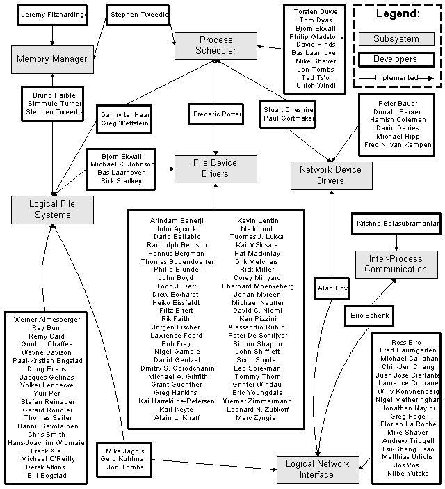 |
| Figure 2.3: Division of Developer Responsibilities |
Figure 2.3 shows most of the developers who have worked on the Linux kernel, and the areas that they appeared to have implemented. A few developers modified many parts of the kernel; for clarity, these developers were not included. For example, Linus Torvalds was the original implementor of most of the kernel subsystems, although subsequent development was done by others. This diagram can’t be considered accurate because developer signatures were not maintained consistently during the development of the kernel, but it gives a general idea of what systems developers spent most of their effort implementing.
This diagram confirms the large-scale structure of the kernel as outlined earlier. It is interesting to note that very few developers worked on more than one system; where this did occur, it occurred mainly where there is a subsystem dependency. The organization supports the well-known rule of thumb stated by Melvin Conway (see [Raymond 1993]) that system organization often reflects developer organization. Most of the developers worked on hardware device drivers, logical file system modules, network device drivers, and network protocol modules. It’s not surprising that these four areas of the kernel have been architected to support extensibility the most.
2.5 System Data Structures
2.5.1 Task List
The process scheduler maintains a block of data for each process that is active. These blocks of data are stored in a linked list called the task list; the process scheduler always maintains a current pointer that indicates the current process that is active.
2.5.2 Memory Map
The memory manager stores a mapping of virtual to physical addresses on a per-process basis, and also stores additional information on how to fetch and replace particular pages. This information is stored in a memory-map data structure that is stored in the process scheduler’s task list.
2.5.3 I-nodes
The Virtual File System uses index-nodes (i-nodes) to represent files on a logical file system. The i-node data structure stores the mapping of file block numbers to physical device addresses. I-node data structures can be shared across processes if two processes have the same file open. This sharing is accomplished by both task data blocks pointing to the same i-node.
2.5.4 Data Connection
All of the data structures are rooted at the task list of the process scheduler. Each process on the system has a data structure containing a pointer to its memory mapping information, and also pointers to the i-nodes representing all of the opened files. Finally, the task data structure also contains pointers to data structures representing all of the opened network connections associated with each task.
3. Subsystem Architectures
3.1 Process Scheduler Architecture
3.1.1 Goals
The process scheduler is the most important subsystem in the Linux kernel. Its purpose is to control access to the computer’s CPU(s). This includes not only access by user processes, but also access for other kernel subsystems.
3.1.2 Modules
The scheduler is divided into four main modules:
- The scheduling policy module is responsible for judging which process will have access to the CPU; the policy is designed so that processes will have fair access to the CPU.
- Architecture-specific modules are designed with a common interface to abstract the details of any particular computer architecture. These modules are responsible for communicating with a CPU to suspend and resume a process. These operations involve knowing what registers and state information need to be preserved for each process and executing the assembly code to effect a suspend or resume operation.
- The architecture-independent module communicates with the policy module to determine which process will execute next, then calls the architecture-specific module to resume the appropriate process. In addition, this module calls the memory manager to ensure that the memory hardware is restored properly for the resumed process.
The system call interface module permits user processes access to only those resources that are explicitly exported by the kernel. This limits the dependency of user processes on the kernel to a well-defined interface that rarely changes, despite changes in the implementation of other kernel modules.
 |
| Figure 3.1: Process Scheduler Subsystem in Context |
3.1.3 Data Representation
The scheduler maintains a data structure, the task list, with one entry for each active process. This data structure contains enough information to suspend and resume the processes, but also contains additional accounting and state information. This data structure is publicly available throughout the kernel layer
3.1.4 Dependencies, Data Flow, and Control Flow
The process scheduler calls the memory manager subsystem as mentioned earlier; because of this, the process scheduler subsystem depends on the memory manager subsystem. In addition, all of the other kernel subsystems depend on the process scheduler to suspend and resume processes while waiting for hardware requests to complete. These dependencies are expressed through function calls and access to the shared task list data structure. All kernel subsystems read and write the data structure representing the current task, leading to bi-directional data flow throughout the system.
In addition to the data and control flow within the kernel layer, the O/S services layer provides an interface for user processes to register for timer notification. This corresponds to the implicit execution architectural style described in [Garlan 1994]. This leads to a flow of control from the scheduler to the user processes. The usual case of resuming a dormant process is not considered a flow of control in the normal sense because the user process cannot detect this operation. Finally, the scheduler communicates with the CPU to suspend and resume processes; this leads to a data flow, and a flow of control. The CPU is responsible for interrupting the currently executing process and allowing the kernel to schedule another process.
3.2 Memory Manager Architecture
3.2.1 Goals
The memory manager subsystem is responsible for controlling process access to the hardware memory resources. This is accomplished through a hardware memory-management system that provides a mapping between process memory references and the machine’s physical memory. The memory manager subsystem maintains this mapping on a per process basis, so that two processes can access the same virtual memory address and actually use different physical memory locations. In addition, the memory manager subsystem supports swapping; it moves unused memory pages to persistent storage to allow the computer to support more virtual memory than there is physical memory.
3.2.2 Modules
The memory manager subsystem is composed of three modules:
- The architecture specific module presents a virtual interface to the memory management hardware
- The architecture independent manager performs all of the per-process mapping and virtual memory swapping. This module is responsible for determining which memory pages will be evicted when there is a page fault — there is no separate policy module since it is not expected that this policy will need to change.
- A system call interface is provided to provide restricted access to user processes. This interface allows user processes to allocate and free storage, and also to perform memory mapped file I/O.
3.2.3 Data Representation
The memory manager stores a per-process mapping of physical addresses to virtual addresses. This mapping is stored as a reference in the process scheduler’s task list data structure. In addition to this mapping, additional details in the data block tell the memory manager how to fetch and store pages. For example, executable code can use the executable image as a backing store, but dynamically allocated data must be backed to the system paging file. Finally, the memory manager stores permissions and accounting information in this data structure to ensure system security.
 |
| Figure 3.2: Memory Manager subsystem in context |
3.2.4 Data Flow, Control Flow, and Dependencies
The memory manager controls the memory hardware, and receives a notification from the hardware when a page fault occurs — this means that there is bi-directional data and control flow between the memory manager modules and the memory manager hardware. Also, the memory manager uses the file system to support swapping and memory mapped I/O. This requirement means that the memory manager needs to make procedure calls to the file system to store and fetch memory pages from persistent storage. Because the file system requests cannot be completed immediately, the memory manager needs to suspend a process until the memory is swapped back in; this requirement causes the memory manager to make procedure calls into the process scheduler. Also, since the memory mapping for each process is stored in the process scheduler’s data structures, there is a bi-directional data flow between the memory manager and the process scheduler. User processes can set up new memory mappings within the process address space, and can register themselves for notification of page faults within the newly mapped areas. This introduces a control flow from the memory manager, through the system call interface module, to the user processes. There is no data flow from user processes in the traditional sense, but user processes can retrieve some information from the memory manager using select system calls in the system call interface module.
3.3 Virtual File System Architecture
 |
| Figure 3.3: Virtual File System in Context |
3.3.1 Goals
The virtual file system is designed to present a consistent view of data as stored on hardware devices. Almost all hardware devices in a computer are represented using a generic device driver interface. The virtual file system goes further, and allows the system administrator to mount any of a set of logical file systems on any physical device. Logical file systems promote compatibility with other operating system standards, and permit developers to implement file systems with different policies. The virtual file system abstracts the details of both physical device and logical file system, and allows user processes to access files using a common interface, without necessarily knowing what physical or logical system the file resides on.
In addition to traditional file-system goals, the virtual file system is also responsible for loading new executable programs. This responsibility is accomplished by the logical file system module, and this allows Linux to support several executable formats.
3.3.2 Modules
- There is one device driver module for each supported hardware controller. Since there are a large number of incompatible hardware devices, there are a large number of device drivers. The most common extension of a Linux system is the addition of a new device driver.
- The Device Independent Interface module provides a consistent view of all devices.
- There is one logical file system module for each supported file system.
- The system independent interface presents a hardware and logical-file-system independent view of the hardware resources. This module presents all resources using either a block-oriented or character-oriented file interface.
- Finally, the system call interface provides controlled access to the file system for user processes. The virtual file system exports only specific functionality to user processes.
3.3.3 Data Representation
All files are represented using i-nodes. Each i-node structure contains location information for specifying where on the physical device the file blocks are. In addition, the i-node stores pointers to routines in the logical file system module and device driver that will perform required read and write operations. By storing function pointers in this fashion, logical file systems and device drivers can register themselves with the kernel without having the kernel depend on any specific module.
3.3.4 Data Flow, Control Flow, and Dependencies
One specific device driver is a ramdisk; this device allocates an area of main memory and treats it as a persistent-storage device. This device driver uses the memory manager to accomplish its tasks, and thus there is a dependency, control flow, and data flow between the file system device drivers and the memory manager.
One of the specific logical file systems that is supported is the network file system (as a client only). This file system accesses files on another machine as if they were part of the local machine. To accomplish this, one of the logical file system modules uses the network subsystem to complete its tasks. This introduces a dependency, control flow, and data flow between the two subsystems.
As mentioned in section 3.2, the memory manager uses the virtual file system to accomplish memory swapping and memory-mapped I/O. Also, the virtual file system uses the process scheduler to disable processes while waiting for hardware requests to complete, and resume them once the request has been completed. Finally, the system call interface allows user processes to call in to the virtual file system to store or retrieve data. Unlike the previous subsystems, there is no mechanism for users to register for implicit invocation, so there is no control flow from the virtual file system towards user processes (resuming processes is not considered control flow).
3.4 Network Interface Architecture
3.4.1 Goals
The network subsystem allows Linux systems to connect to other systems over a network. There are a number of possible hardware devices that are supported, and a number of network protocols that can be used. The network subsystem abstracts both of these implementation details so that user processes and other kernel subsystems can access the network without necessarily knowing what physical devices or protocol is being used.
3.4.2 Modules
- Network device drivers communicate with the hardware devices. There is one device driver module for each possible hardware device.
- The device independent interface module provides a consistent view of all of the hardware devices so that higher levels in the subsystem don’t need specific knowledge of the hardware in use.
- The network protocol modules are responsible for implementing each of the possible network transport protocols.
- The protocol independent interface module provides an interface that is independent of hardware devices and network protocol. This is the interface module that is used by other kernel subsystems to access the network without having a dependency on particular protocols or hardware.
Finally, the system calls interface module restricts the exported routines that user processes can access.
 |
| Figure 3.4: Network Interface Subsystem in Context |
3.4.3 Data Representation
Each network object is represented as a socket. Sockets are associated with processes in the same way that i-nodes are associated; sockets can be share amongst processes by having both of the task data structures pointing to the same socket data structure.
3.4.4 Data Flow, Control Flow, and Dependencies
The network subsystem uses the process scheduler to suspend and resume processes while waiting for hardware requests to complete (leading to a subsystem dependency and control and data flow). In addition, the network subsystem supplies the virtual file system with the implementation of a logical file system (NFS) leading to the virtual file system depending on the network interface and having data and control flow with it.
3.5 Inter-Process Communication Architecture
The architecture of the inter-process communication subsystem is omitted for brevity since it is not as interesting as the other subsystems.
4. Conclusions
The Linux kernel is one layer in the architecture of the entire Linux system. The kernel is conceptually composed of five major subsystems: the process scheduler, the memory manager, the virtual file system, the network interface, and the inter-process communication interface. These subsystems interact with each other using function calls and shared data structures.
At the highest level, the architectural style of the Linux kernel is closes to Garlan and Shaw’s Data Abstraction style ([Garlan1994]); the kernel is composed of subsystems that maintain internal representation consistency by using a specific procedural interface. As each of the subsystems is elaborated, we see an architectural style that is similar to the layered style presented by Garlan and Shaw. Each of the subsystems is composed of modules that communicate only with adjacent layers.
The conceptual architecture of the Linux kernel has proved its success; essential factors for this success were the provision for the organization of developers, and the provision for system extensibility. The Linux kernel architecture was required to support a large number of independent volunteer developers. This requirement suggested that the system portions that require the most development — the hardware device drivers and the file and network protocols — be implemented in an extensible fashion. The Linux architect chose to make these systems be extensible using a data abstraction technique: each hardware device driver is implemented as a separate module that supports a common interface. In this way, a single developer can add a new device driver, with minimal interaction required with other developers of the Linux kernel. The success of the kernel implementation by a large number of volunteer developers proves the correctness of this strategy.
Another important extension to the Linux kernel is the addition of more supported hardware platforms. The architecture of the system supports this extensibility by separating all hardware-specific code into distinct modules within each subsystem. In this way, a small group of developers can effect a port of the Linux kernel to a new hardware architecture by re-implementing only the machine-specific portions of the kernel.
Источник


