- USB как паралелльный порт.
- Re: USB как паралелльный порт.
- USB как паралелльный порт.
- Re: USB как паралелльный порт.
- Re: USB как паралелльный порт.
- USB как паралелльный порт.
- Re: USB как паралелльный порт.
- Re: USB как паралелльный порт.
- USB как паралелльный порт.
- Re: USB как паралелльный порт.
- Re: USB как паралелльный порт.
- forum-bolid.ru
- Linux vs rs485-USB
- Линукс
- Линукс
- Линукс
- Линукс
- Read a MODBUS temperature sensor through USB-RS485 adapter on Ubuntu and Raspberry Pi
- Connecting the adapter, learning the device name
- Programming in C with libmodbus
- Reading the temperature using minimalmodbus in Python
- Reading the temperature using pymodbus in Python
USB как паралелльный порт.
Добрый день! Не подскажите, как настроить ОС Linux на работу с преобразователем USB в RS-485? (Что я должен сделать чтоб появился, например, файл типа /dev/ttyUSB0 связанный с USB-устройством). Или ссылку на документацию в которой есть подробный пример. (В Windows, аналогичное, делается путём установки нужного драйвера. В Linuxe по моим предположениям должен быть универсальный драйвер (pl2303)для работы с данными устройствами, только не знаю где он находится и как его подключать).

Re: USB как паралелльный порт.
Этот драйвер уже есть во всех дистрибутивных ядрах и должен загружаться автоматически при подключении устройства, основанного на поддерживаемом чипе. Кроме того, его можно загрузить вручную: modprobe pl2303.
Драйвер не является универсальным, а содержит большую таблицу идентификаторов устройств, с которыми он работает. Динамическое добавление новых идентификаторов в этом драйвере не предусмотрено.
Для получения более подробной информации по использованию вашего устройства в Linux, прошу предоставить вывод команды lsusb с подключенным преобразователем.

USB как паралелльный порт.
lsusb Bus 002 Device 002: ID 1555:0004 Bus 002 Device 001: ID 0000:0000 Bus 005 Device 001: ID 0000:0000 Bus 003 Device 001: ID 0000:0000 Bus 004 Device 001: ID 0000:0000 Bus 001 Device 001: ID 0000:0000
Re: USB как паралелльный порт.
> Bus 002 Device 002: ID 1555:0004
Это неизвестный науке зверь. Можно попытаться подсунуть его ID модулю usbserial (см. ниже), но я не гаранитрую, что это поможет.
modprobe usbserial vendor=0x1555 product=0x0004
(если это не заработает, другого решения не знаю)
Re: USB как паралелльный порт.
Хотя стоп. Это точно должно дать /dev/ttyUSBx? Если это преобразователь в параллельный порт, то, может, правильнее будет использовать драйвер usblp?
Вывод lsusb -v в студию — хочу посмотреть, в частности, класс устройства.
USB как паралелльный порт.
Есть так же другой преобразователь (I-7561, первый преобразователь фирмы Овен). lsusb для I-7561.
Bus 002 Device 003: ID 067a:7561
Bus 002 Device 001: ID 0000:0000
Bus 005 Device 001: ID 0000:0000
Bus 003 Device 001: ID 0000:0000
Bus 004 Device 001: ID 0000:0000
Bus 001 Device 001: ID 0000:0000
нашёл какой-то драйвер под Linux для I-7561, попробывал выполнить команду make (скомпилировать) выдаёт ошибку ругается на какие-то функции названия которых начинается с __. #include все находит.
Re: USB как паралелльный порт.
> Bus 002 Device 003: ID 067a:7561
Тоже неизвестный науке зверь. lsusb -v в студию при двух подключенных преобразователях.
Re: USB как паралелльный порт.
> Bus 002 Device 003: ID 067a:7561
Этот у других завелся по описанной выше методике с указанием ID модулю usbserial
USB как паралелльный порт.
Bus 002 Device 004: ID 1555:0004
bDeviceClass 0 (Defined at Interface level)
iManufacturer 1 Silicon Labs
iProduct 2 AC4 USB to RS-485 Converter
bInterfaceClass 255 Vendor Specific Class
iInterface 2 AC4 USB to RS-485 Converter
bEndpointAddress 0x81 EP 1 IN
Transfer Type Bulk
Synch Type None
Usage Type Data
wMaxPacketSize 0x0040 1x 64 bytes
bEndpointAddress 0x01 EP 1 OUT
Transfer Type Bulk
Synch Type None
Usage Type Data
wMaxPacketSize 0x0040 1x 64 bytes
Re: USB как паралелльный порт.
Стоп, вру. Но, судя по тому, что идентификатор устройства нигде, кроме таблицы устройств, в нерабочем драйвере от http://www.icp-das.ru/support/ не появляется, попробуй сделать так.
1) Скачай с http://www.kernel.org/ ядро 2.6.22.6 (linux-2.6.22.6.tar.bz2)
2) В файл linux-2.6.22.6/drivers/usb/serial/pl2303.h в конец добавь:
#define ICPDAS_VID 0x067a
#define ICPDAS_PID_I7561 0x7561
#define ICPDAS_VID_2 0x067c
#define ICPDAS_PID_I7563 0x7563
3) В файле linux-2.6.22.6/drivers/usb/serial/pl2303.c найди static struct usb_device_id id_table, там будет таблица устройств. Добавь в конец:
4) (не уверен, что это надо) В файле linux-2.6.22.6/drivers/usb/serial/pl2303.c найди кусок, где делается куча вызовов FISH и SOUP. Непосредственно перед kfree(buf) добавь:
SOUP (VENDOR_WRITE_REQUEST_TYPE, VENDOR_WRITE_REQUEST, 1, 0xc0);
SOUP (VENDOR_WRITE_REQUEST_TYPE, VENDOR_WRITE_REQUEST, 2, 4);
Не исключено, что два других вызова SOUP с третьим параметром, равным 1 и 2 соответственно, придется убрать. Или поместить строки выше вместо них. Короче, поэкспериментируй с этим куском кода.
После перекомпиляции ядро должно будет поддержать твой второй конвертер.
Re: USB как паралелльный порт.
Оопс. Я был неправ, когда говорил, что добавление новых идентификаторов не предусмотрено. Ничего компилировать не надо.
modprobe pl2303
echo 067a 7561 >/sys/bus/usb-serial/drivers/pl2303/new_id
echo 1555 0004 >/sys/bus/usb-serial/drivers/pl2303/new_id
Источник
forum-bolid.ru
Linux vs rs485-USB
Доброе время суток, помогите запустить юсб свисток под вайном. Пользоваться не лицензионным ПО не хочу, а платить за лицензию Виндовс не имею желания, так как только для программирования приборов её требуется установить (пользуюсь линуксом)
На форумах линукса писал, толку нет, никто с этим не сталкивался. Специфика работы, видели те. А все знакомые, кто связан с пожарной охранной сигнализацией сидят на пиратский дистрибутивах, зачем мне оно?
Помогите, кто чем может.
После подключения свистка появляется среди прочего ACM0
/home/delovoy$ setserial -a /dev/ttyACM0
/dev/ttyACM0, Line 0, UART: unknown, Port: 0x0000, IRQ: 0
Baud_base: 115200, close_delay: 12, divisor: 0
closing_wait: none
Flags: spd_normal low_latency
И все, более нет ничего подобного. Галочку ставить негде, тут консоль только
Свисток новый. У знакомого проверял свисток, все работало, конфиги читает, пишет.
Линукс
dmesg | tail
[ 808.629705] cdc_acm 1-2:1.0: ttyACM0: USB ACM device
[ 1181.600285] brcmsmac bcma0:1: wl0: brcms_c_d11hdrs_mac80211: txop exceeded phylen 153/256 dur 1730/1504
[ 2236.431213] usb 1-2: USB disconnect, device number 5
[ 2237.807368] usb 1-2: new full-speed USB device number 6 using xhci_hcd
[ 2237.963258] usb 1-2: New USB device found, idVendor=04e2, idProduct=1411
[ 2237.963269] usb 1-2: New USB device strings: Mfr=1, Product=2, SerialNumber=3
[ 2237.963274] usb 1-2: Product: XR21B1411
[ 2237.963278] usb 1-2: Manufacturer: Exar Corp.
[ 2237.963281] usb 1-2: SerialNumber: H7925505141
[ 2237.966451] cdc_acm 1-2:1.0: ttyACM0: USB ACM device
uname -a
Linux IdeaPad 3.19.0-25-generic #26
14.04.1-Ubuntu SMP Fri Jul 24 21:16:20 UTC 2015 x86_64 x86_64 x86_64 GNU/Linux
Линукс
Свисток установил, осталось только проверить его работоспособность. Сделал следующее, нашел тут модуль под своё ядро. Скомпилил и установил. Свисток определяется теперь как: ttyXRUSB0, прокинул символическую ссылку на com1 в .wine/dosdevices/com1 и сменил владельца подключаемого свистка. Посмотрим что получиться, если приборы будут определяться, то напишу по шагам подробно.
У меня предчувствие, что все заработает. Так как при подключенном свистке пытаюсь найти приборы (которые не подключены) и он пытается найти, мигает диод как в нормальном режиме. Но рано делать выводы. В понедельник точно узнаю =)
Линукс
Линукс
Нет. Установил, но путь не появился
По дефолту выставлено у меня вин хп.
Готово, оказывается bolid, а не orion
Что еще можно сделать? Я вот что думаю, надо мне было устанавливать модуль XRUSB или нет? Этот модуль в логи гадит больше чем сама система. И заработает ли с ним? Вы не ставили модуль этот? Оставили так, как было (ttyAMC0)?
ПК (Орион Про, UProg) — RS485 -> С2000-Ehernet -> С2000-Ehernet -> RS485 — Сигнал-20П (Как настроить?)
Доброго времени суток!
И заранее спасибо за ответ!
Возникла необходимость настроить схему, описанную выше. Без RS232 к ПК и.
Доброго всем времени суток и с наступающим новым годом!
Помогие, пожалуйста, разобраться с проектным решением по переключению интерфейса RS485. На проектантов надежды нет, поскольку они сменились, уволились и пропали — никто ничего вразумительного.
Источник
Read a MODBUS temperature sensor through USB-RS485 adapter on Ubuntu and Raspberry Pi
Running MODBUS/RTU over an RS485 network is pretty cool, in an old-school way. The technique was invented decades ago, and allowed you to connect to a few dozen MODBUS devices over simple twisted pair copper wire, over a thousand feet distance or more. It’s such a successful technique that it has not been supplanted by new modern communication technologies like TCP/IP. Unfortunately most modern computers do not have RS-485 interfaces. Fortunately there are many USB-RS485 adapters available. In this article we’ll use a cheap USB-RS485 adapter on both a Raspberry Pi and a regular x86 Linux box to communicate with a simple MODBUS temperature sensor.
What we’ll do is create simple MODBUS client programs, in C and Python, to communicate with the chosen temperature sensor device.
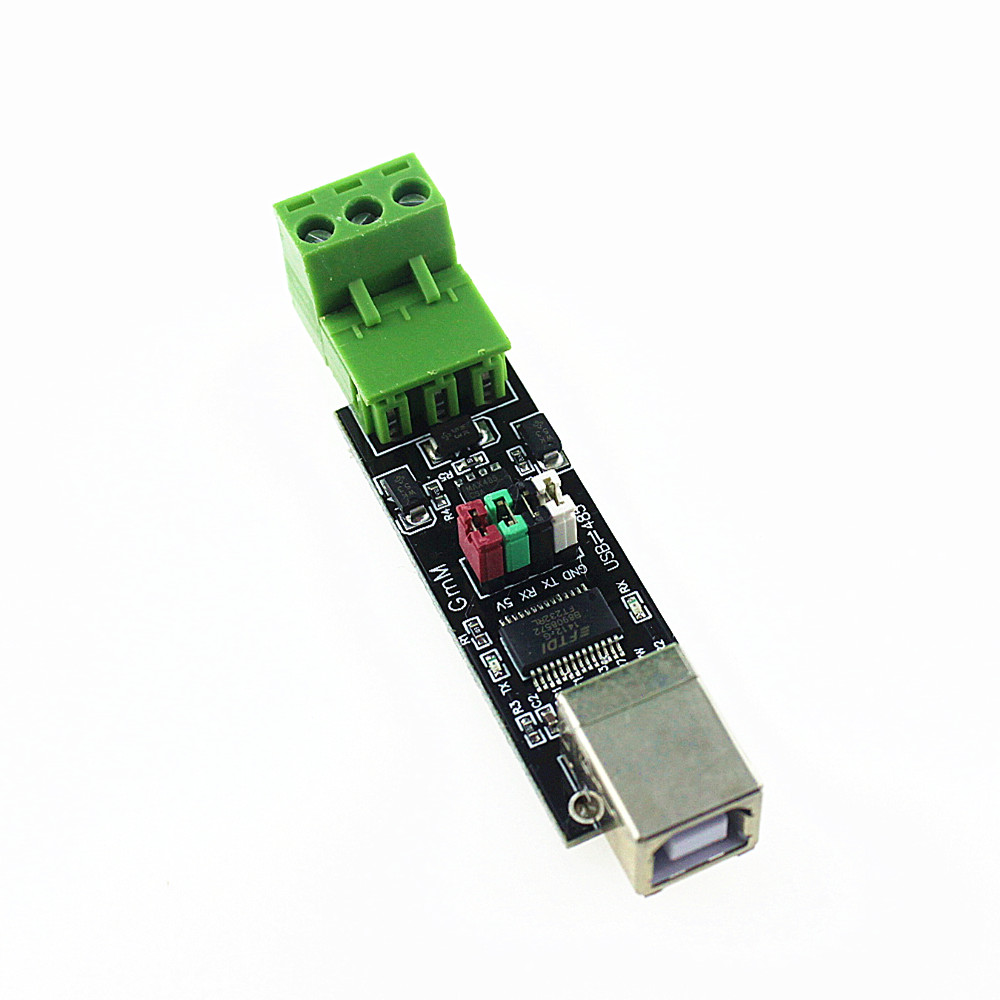
For this project, we’re using a cheap MODBUS temperature sensor that’s probably not suitable for production use, but is good enough for small scale experimentation and learning. (See Overview of a simple MODBUS/RTU RS-485 temperature sensor) Additionally we’re using this USB-to-RS485 adapter card:
I’ve only used this device on Ubuntu, Raspbian (Raspberry Pi), and Mac OS X. Essentially you plug it into a USB port on your computer, and attach a MODBUS device to the jumper block, then run MODBUS software. On those operating systems a /dev/ttySOMETHING device is automatically set up, which you’ll have to determine from the system log. The software has to connect through that device, and most of the details are automatically taken care of for you.
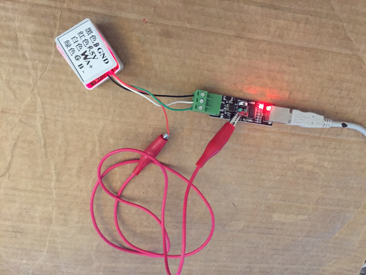
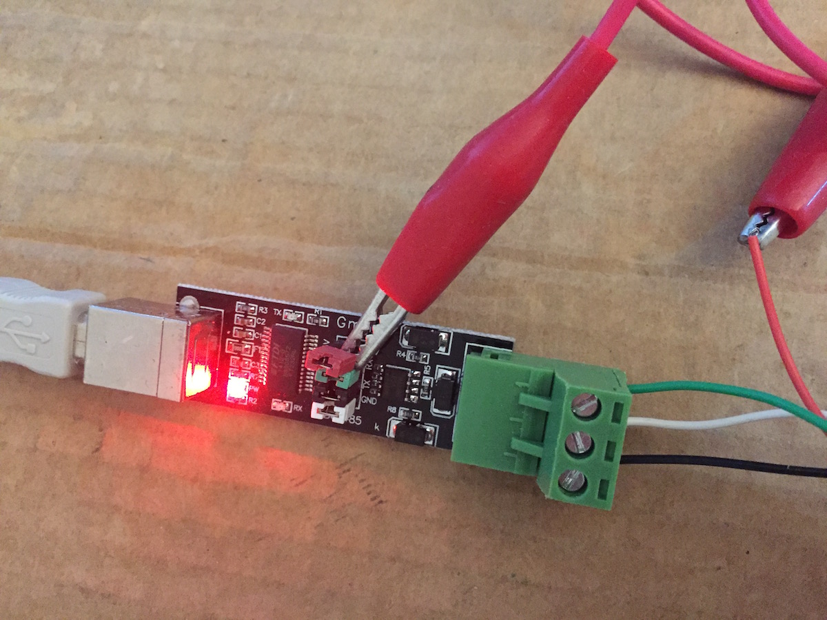
These pictures show details of wiring the USB-to-RS485 adapter with this particular MODBUS device.
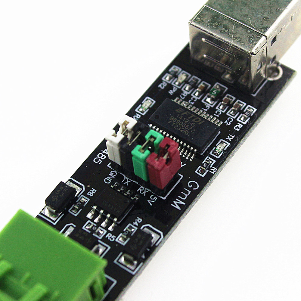
The device requires a 5 volt power supply, and the simplest way to get that power is via the jumper on the adapter board. The manufacturer did not bring the 5 volt connector out to the jumper block, but it is available there on the jumper pin. It’s just a matter of connecting to that jumper pin using an extension cord. Otherwise «A» on the device is connected to «A» on the adapter, «B» on the device is connected to «B» on the adapter, as is «GND».
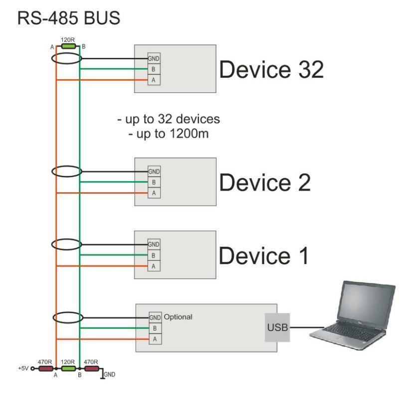
In theory this is how you connect multiple devices to this adapter. I have not tried this, however. It appears from the diagram that in this case, you’re to use shielded cable, and the GND connection on each adapter board is to be connected to shield, which would then be connected to ground somewhere.
Connecting the adapter, learning the device name
On connecting the device to a USB port, the Linux/Unix kernel will scan the device and figure out what it is. For Linux, the device is automatically recognized (usually) and a series of messages like this might be printed:
The last line says the device name, in this case /dev/ttyUSB1 .
If you should need to know, the manufacturer is at: http://www.ftdichip.com/ Their chips are in a wide variety of products, and there is driver software on their site if you need it.
Programming in C with libmodbus
Okay, enough with setup let’s get on with some code. We’ll start with libmodbus because it’s universally available, see http://libmodbus.org/
For Ubuntu, and on Raspbian, you install the libmodbus-dev and libmodbus5 packages:
Once installed, we have this code for your perusal:
Remember the device we’re using is addressed as device ID 1, and we are to read register 1 for the temperature value.
The modbus_new_rtu function creates a MODBUS/RTU object. With modbus_set_slave we set the device ID to work with, and with modbus_connect we connect to the device.
There is a commented-out section where we would call modbus_rtu_set_serial_mode . With the USB adapter we have, the settings controlled by that function are handled for us automatically, and if we call that function errors will be generated.
We set up a buffer to receive data from the MODBUS device. Each MODBUS register is 16 bits (a.k.a. «1 word») and we’ve allocated space for two registers. You should of course allocate space depending on the number of registers you’ll be reading.
Then, in a loop, with a 1-second delay per iteration, we call modbus_read_input_registers to read from the device. Output is shown below.
The modbus_get_response_timeout and modbus_get_response_timeout functions have different signatures depending on the libmodbus version. To accommodate that difference we’ve got code you can comment/uncomment to match the library version.
To compile the program, type this:
Then run it as so:
Reading the temperature using minimalmodbus in Python
Compared to the libmodbus example using minimalmodbus in Python will feel like a nice cool breeze. This library makes MODBUS programming very simple, though it is on the limited side.
Then type this in as temp.py
Before setting up the MODBUS connection, it’s possible to set connection parameters (baud rate, etc) by assigning values to the minimalmodbus object. Then you connect to the device, minimalmodbus.Instrument , and interact with it using the API.
The instrument.read_register command reads a single register, to read multiple registers use instrument.read_registers . It takes the register number, and an indicator of the number of decimal points, and finally the function code. Function code 4 reads from the Holding Registers, of course.
The number of decimal points is the same issue where we divided by 100.0 in the C code. This device stores the temperature in Centigrade, but as an integer 100x than the actual value. For display you divide by 100, and automatically get two digits of precision.
Output will look like this:
Reading the temperature using pymodbus in Python
The pymodbus library is far more comprehensive than minimalmodbus in that you can do a lot more with it. It does mean the library is harder to use.
Источник


