- Создание и настройка виртуальных сетевых интерфейсов в Linux
- 1. Введение
- 2. Временный виртуальный сетевой интерфейс
- 2.1. Отключение виртуального сетевого интерфейса
- 3. Присвоение виртуальному интерфейсу постоянного адреса
- 3.1. Debian / Ubuntu
- 3.1.1. Статический адрес
- 3.1.2. Dhcp
- 3.2. Redhat / Fedora / CentOS
- 3.2.1. Статический адрес
- 3.2.2. Dhcp
- 4. Заключение
- mtds / lvn.md
- Русские Блоги
- Как настроить VIP (виртуальный IP) под Linux
- Интеллектуальная рекомендация
- Пошаговая загрузка файла Spring MVC-09 (на основе файла загрузки клиента Servlet3.0 + Html5)
- Создайте многоканальное окно в приложениях Win32
- Путь к рефакторингу IOS-APP (3) Введение в модульное тестирование
- Tree——No.617 Merge Two Binary Trees
- Introduction to Linux interfaces for virtual networking
- Bridge
- Bonded interface
- Team device
- VXLAN
- MACVLAN
- IPVLAN
- MACVTAP/IPVTAP
- MACsec
- VXCAN
- IPOIB
- NLMON
- Dummy interface
- Additional resources
- netdevsim interface
Создание и настройка виртуальных сетевых интерфейсов в Linux
1. Введение
Знаете ли вы, что можете присвоить более чем один IP-адрес физическому сетевому интерфейсу? Эта техника очень полезна, например при работе с Apache и виртуальными хостами, так как позволяет получить доступ к одному и тому же серверу Apache с двух разных IP-адресов.
2. Временный виртуальный сетевой интерфейс
Процесс создания виртуального сетевого интерфейса в Linux не занимает много времени. Он включает один запуск команды ifconfig.
Приведенная выше команда создает виртуальный сетевой интерфейс, базирующийся на оригинальном физическом сетевом интерфейсе eth0. Самое важное условие для создания виртуального сетевого интерфейса — должен существовать физический сетевой интерфейс, в нашем случае eth0. Ниже приведен полный пример:
Теперь мы можем настроить новый виртуальный интерфейс на базе eth0. После выполнения команды ifconfig новый виртуальный интерфейс готов к немедленному использованию.
2.1. Отключение виртуального сетевого интерфейса
Для отключения нашего, созданного ранее, временного сетевого интерфейса мы можем также использовать команду ifconfig с флагом down.
3. Присвоение виртуальному интерфейсу постоянного адреса
Описанные выше настройки не сохраняются после перезагрузки. Если вы хотите, чтобы виртуальный сетевой интерфейс работал постоянно, необходимо модифицировать конфигурационные файлы в соответствии с требованиями вашего дистрибутива Linux. Ниже описан этот процесс для самых распространенных дистрибутивов:
3.1. Debian / Ubuntu
3.1.1. Статический адрес
В Debian или Ubuntu вам необходимо отредактировать файл /etc/network/interfaces, добавив в него следующие строки:
3.1.2. Dhcp
Возможно также использовать витруальный сетевой интерфейс с DHCP. В этом случае вам необходимо добавить в /etc/network/interfaces следующую строку:
Для того, чтобы изменения вступили в силу, необходимо перезапустить сеть:
3.2. Redhat / Fedora / CentOS
3.2.1. Статический адрес
В Redhat, Fedora или CentOS Linux директория, отвечающая за присвоение постоянных IP-адресов — это /etc/sysconfig/network-scripts. В этой директории необходимо создать файл, соответствующий вашему новому виртуальному интерфейсу. В нашем случае этот файл будет называться ifcfg-eth0:0. Создайте этот новый файл и вставьте в него приведенные ниже строки. После перезагрузки адрес будет присвоен виртуальному интерфейсу на постоянной основе.
3.2.2. Dhcp
Когда закончите, перезапустите ваши интерфейсы:
4. Заключение
Раньше один физический сервер обслуживал один веб-сайт. Сегодня такой способ хостинга уже не является жизнеспособным, поэтому способность операционной системы создавать виртуальные сетевые интерфейсы действительно необходима.
Источник
mtds / lvn.md
Virtual Networking on Linux
In the Linux Kernel, support for networking hardware and the methods to interact with these devices is standardized by the socket API:
In order to support new kind of computational workloads, different deployment scenarios and a better use of HW resources the Linux OS supports virtualization of different computing resources: CPU, memory, storage and networking. Virtual networking capabilities are indeed used as a basis for hosting VMs and containers.
A general overview of virtual networking components available in Linux is described in this article from the IBM developerworks web site.
Types of virtual Network Interfaces
- Bridge: A Linux bridge behaves like a network switch. It forwards packets between interfaces that are connected to it. It’s usually used for forwarding packets on routers, on gateways, or between VMs and network namespaces on a host. It also supports STP, VLAN filter, and multicast snooping.
- TUN: TUN (network Tunnel) devices work at the IP level or layer three level of the network stack and are usually point-to-point connections. A typical use for a TUN device is establishing VPN connections since it gives the VPN software a chance to encrypt the data before it gets put on the wire. Since a TUN device works at layer three it can only accept IP packets and in some cases only IPv4. If you need to run any other protocol over a TUN device you’re out of luck. Additionally because TUN devices work at layer three they can’t be used in bridges and don’t typically support broadcasting.
- TAP: TAP (terminal access point) devices, in contrast, work at the Ethernet level or layer two and therefore behave very much like a real network adaptor. Since they are running at layer two they can transport any layer three protocol and aren’t limited to point-to-point connections. TAP devices can be part of a bridge and are commonly used in virtualization systems to provide virtual network adaptors to multiple guest machines. Since TAP devices work at layer two they will forward broadcast traffic which normally makes them a poor choice for VPN connections as the VPN link is typically much narrower than a LAN network (and usually more expensive).
- VETH: Virtual Ethernet interfaces are essentially a virtual equivalent of a patch cable, what goes in one end comes out the other. When either device is down, the link state of the pair is down.
An example of creating a bridge:
Enslaving a network interface to a bridge:
An example of creating two virtual ethernet interfaces (ep1,ep2) and linking them together:
veth interfaces can also be linked to a bridge:
It is also possible to add IP addresses to the interfaces, for example:
All the network interfaces available will be shown with: ip address show
Many other types of virtual network interfaces are available, as described in this post from the RedHat developers blog.
Namespaces are a feature available on the Linux kernel which is used as a basis for many software technology like Linux Containers (LXC), Docker and software-defined network (SDN) solutions. It basically allows to define and use multiple virtual instances of the resources available on a host.
Linux namespaces include (additional references are available in the man page):
In particular, network namespaces allow individual containers to have exclusive access to virtual network resources, while each container can be assigned a separate network stack.
Network namespaces allows different processes to have different views of the network and different aspects of networking can be isolated between processes:
- Interfaces: different processes can connect to addresses on different interfaces.
- Routes: since processes can see different addresses from different namespaces, they also need different routes to connect to networks on those interfaces.
- Firewall rules: since these are dependant on the source or target interfaces, you may need different firewall rules in different network namespaces.
Handling of network namespaces are done with the ip command, which is part of the iproute2 package.
NOTE: all the commands in the following examples have to be executed directly by root or with root privileges (e.g. with sudo ).
Create, list and delete a network namespace:
ns1 is a network NS which is completely separated from the default one (which is always available after every Linux boot).
Distinct network namespaces can be connected together using veth interfaces:
Virtual ethernet interfaces can be assigned an IP address, inside a network class
Once the IPs are assigned, the veth interfaces have to be brought in UP state:
An example of running a ping command between the two different namespaces through the veth interfaces:
A network namespace can have its own network interface assigned to it, for example the loopback interface (which is by default always present on new network NS but in DOWN state):
It can also have a separated routing table (note that when the network namespace is initially set, the routing table is empty):
Once a network NS is created, it will shows up in multiple places:
A virtual network with network namespaces and a bridge
Considering the following properties:
- network NS can have their own network routes;
- virtual ethernet interfaces comes in pairs;
- it’s possible to assign a network interface to a different network NS;
it is then possible to build an example of multiple network NSs connected together through a Linux bridge and routing rules inside the same physical host. A bridge device give us the virtual equivalent of a network switch, allowing us to connect multiple interfaces (virtual or not), and have them communicate with each other.
The following is a conceptual schema:
- br-veth<1,2>: veth attached to the bridge
- veth<1,2>: veth part of their respective network NS
First, two network NS will be created:
Then two pairs of veth will be created:
Now two of the new veths will be attached to the network NS ( br-veth is just a convenient naming convention but it does not identify a veth connected to a bridge).
The two veth <1,2>will be shown only in their respective networks NS:
Note: the veth1 is marked as DOWN . The same goes for veth2 .
Assign the IP address 192.168.1.11 with netmask 255.255.255.0 to veth1:
An IP address (of the same network class) will be assigned also to veth2 :
Even when the two veth have assigned IP address they cannot communicate between each other: the reason is that there’s no configured interface on the default network namespace which can send the traffic to and from the two veth interfaces.
Adding a bridge it’s the only way to go further:
It can be verified that the bridge is available:
It’s now the time to connect the other two veth interfaces ( br-veth <1,2>) and attach them to the bridge:
In order to reach the veth interfaces through the routing table of the host itself, the bridge needs an IP address:
The brd string force to set the broadcast address (192.168.1.255), specifying the + symbol (255).
The routing table can be checked in this way:
From the global network NS it’s possible to reach both IP addresses (192.168.1.<11,12>) through a simple ping .
It’s also possible to reach ns2 from ns1, once the proper routing is defined:
And reaching ns2 can be tested in the following way:
If the setup will stop at this point, both the network NS will be basically isolated from the outside world: they can only ping each other (providing the internal route is configured) but cannot reach any other IP outside the 192.168.1.0/24 space.
In order to achieve this result we can use NAT (Network Address Translation) through iptables :
The previous command will specify that on the nat table we are appending ( -A ) a rule to the POSTROUTING chain for the source address specified ( -s ) and the action will be MASQUERADE .
Last but not least, the IP forwarding has to be enabled on the networking stack of the host:
A small test: send some packets to 8.8.8.8:
Источник
Русские Блоги
Как настроить VIP (виртуальный IP) под Linux
1. Добавьте VIP вручную
1, ifconfig просмотреть текущую активную сетевую карту. Например: eth0
eth0: 1 указывает целевое устройство сетевой карты, привязанное к этому VIP, 192.168.1.22 — это значение VIP, широковещательный адрес 192.168.1.2, а маска подсети: 255.255.255.0, up означает немедленное включение этого VIP.
3. Запустите ifconfig, чтобы проверить, вступил ли он в силу.
4. Проверить связь 192.168.1.22
5, введите /etc/rc.local для автоматической настройки загрузки
Интеллектуальная рекомендация

Пошаговая загрузка файла Spring MVC-09 (на основе файла загрузки клиента Servlet3.0 + Html5)
пример тестовое задание Исходный код Несмотря на загрузку файлов в Servlet3.0 +, мы можем очень легко программировать на стороне сервера, но пользовательский интерфейс не очень дружелюбен. Одна HTML-ф.

Создайте многоканальное окно в приложениях Win32
Создайте многоканальное окно в приложениях Win32, создайте несколько оконных объектов одного и того же класса Windows, а окна объектов разных классов окон. .

Путь к рефакторингу IOS-APP (3) Введение в модульное тестирование
IOS-APP реконструкция дороги (1) структура сетевых запросов IOS-APP реконструкция дороги (два) Модельный дизайн При рефакторинге нам нужна форма, позволяющая вносить смелые изменения, обеспечивая при .
Tree——No.617 Merge Two Binary Trees
Problem: Given two binary trees and imagine that when you put one of them to cover the other, some nodes of the two trees are overlapped while the others are not. You need to merge them into a new bin.
Источник
Introduction to Linux interfaces for virtual networking

Linux has rich virtual networking capabilities that are used as basis for hosting VMs and containers, as well as cloud environments. In this post, I will give a brief introduction to all commonly used virtual network interface types. There is no code analysis, only a brief introduction to the interfaces and their usage on Linux. Anyone with a network background might be interested in this blog post. A list of interfaces can be obtained using the command ip link help .
This post covers the following frequently used interfaces and some interfaces that can be easily confused with one another:
After reading this article, you will know what these interfaces are, what’s the difference between them, when to use them, and how to create them.
For other interfaces like tunnel, please see An introduction to Linux virtual interfaces: Tunnels
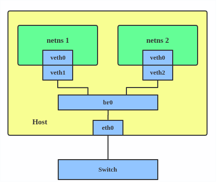
Bridge
A Linux bridge behaves like a network switch. It forwards packets between interfaces that are connected to it. It’s usually used for forwarding packets on routers, on gateways, or between VMs and network namespaces on a host. It also supports STP, VLAN filter, and multicast snooping.
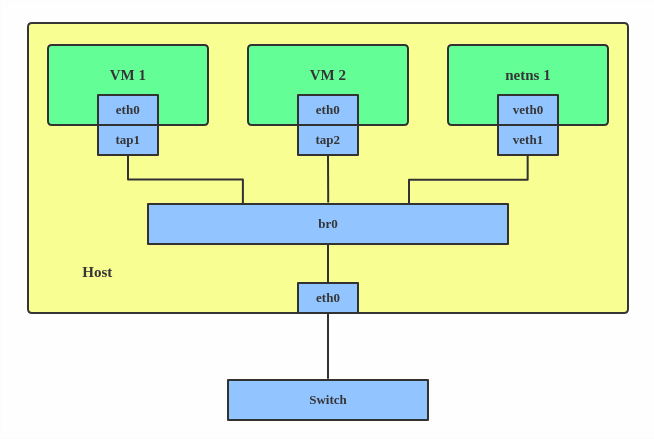
Use a bridge when you want to establish communication channels between VMs, containers, and your hosts.
Here’s how to create a bridge:
This creates a bridge device named br0 and sets two TAP devices ( tap1 , tap2 ), a VETH device ( veth1 ), and a physical device ( eth0 ) as its slaves, as shown in the diagram above.
Bonded interface
The Linux bonding driver provides a method for aggregating multiple network interfaces into a single logical «bonded» interface. The behavior of the bonded interface depends on the mode; generally speaking, modes provide either hot standby or load balancing services.
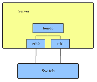
Use a bonded interface when you want to increase your link speed or do a failover on your server.
Here’s how to create a bonded interface:
This creates a bonded interface named bond1 with mode active-backup. For other modes, please see the kernel documentation.
Team device
Similar a bonded interface, the purpose of a team device is to provide a mechanism to group multiple NICs (ports) into one logical one (teamdev) at the L2 layer.

The main thing to realize is that a team device is not trying to replicate or mimic a bonded interface. What it does is to solve the same problem using a different approach, using, for example, a lockless (RCU) TX/RX path and modular design.
But there are also some functional differences between a bonded interface and a team. For example, a team supports LACP load-balancing, NS/NA (IPV6) link monitoring, D-Bus interface, etc., which are absent in bonding. For further details about the differences between bonding and team, see Bonding vs. Team features.
Use a team when you want to use some features that bonding doesn’t provide.
Here’s how to create a team:
This creates a team interface named team0 with mode active-backup , and it adds eth0 and eth1 as team0 ‘s sub-interfaces.
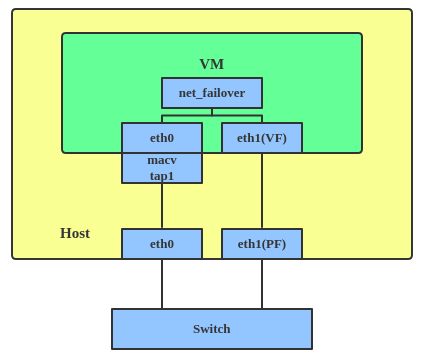
A new driver called net_failover has been added to Linux recently. It’s another failover master net device for virtualization and manages a primary (passthru/VF [Virtual Function] device) slave net device and a standby (the original paravirtual interface) slave net device.
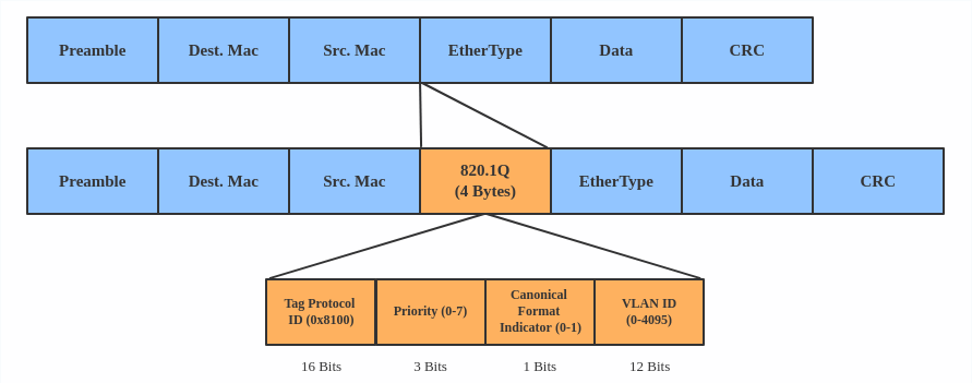
A VLAN, aka virtual LAN, separates broadcast domains by adding tags to network packets. VLANs allow network administrators to group hosts under the same switch or between different switches.
The VLAN header looks like:
Use a VLAN when you want to separate subnet in VMs, namespaces, or hosts.
Here’s how to create a VLAN:
This adds VLAN 2 with name eth0.2 and VLAN 3 with name eth0.3 . The topology looks like this:
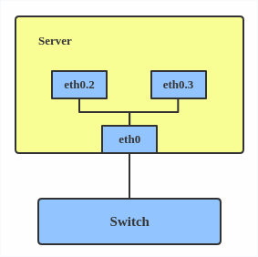
Note: When configuring a VLAN, you need to make sure the switch connected to the host is able to handle VLAN tags, for example, by setting the switch port to trunk mode.
VXLAN
VXLAN (Virtual eXtensible Local Area Network) is a tunneling protocol designed to solve the problem of limited VLAN IDs (4,096) in IEEE 802.1q. It is described by IETF RFC 7348.
With a 24-bit segment ID, aka VXLAN Network Identifier (VNI), VXLAN allows up to 2^24 (16,777,216) virtual LANs, which is 4,096 times the VLAN capacity.
VXLAN encapsulates Layer 2 frames with a VXLAN header into a UDP-IP packet, which looks like this:
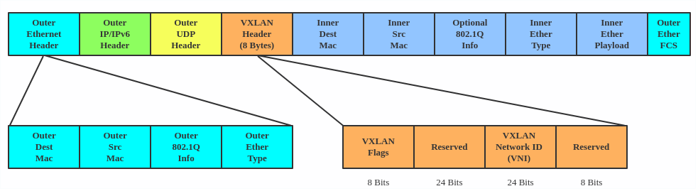
VXLAN is typically deployed in data centers on virtualized hosts, which may be spread across multiple racks.
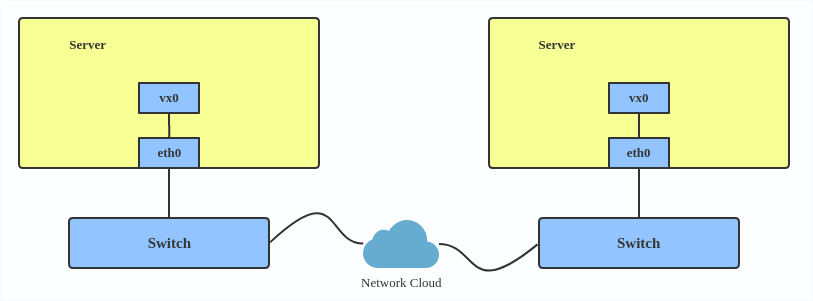
Here’s how to use VXLAN:
MACVLAN
With VLAN, you can create multiple interfaces on top of a single one and filter packages based on a VLAN tag. With MACVLAN, you can create multiple interfaces with different Layer 2 (that is, Ethernet MAC) addresses on top of a single one.
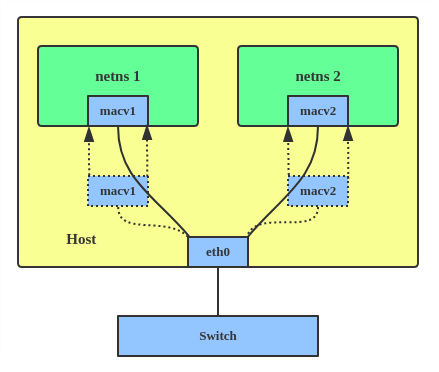
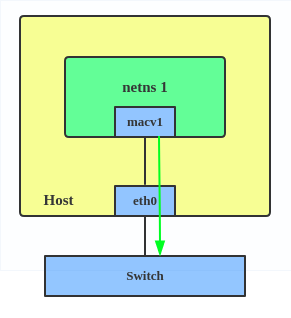
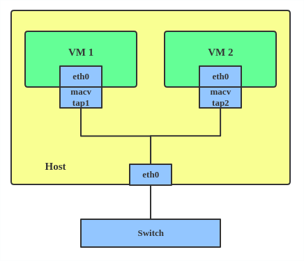
Before MACVLAN, if you wanted to connect to physical network from a VM or namespace, you would have needed to create TAP/VETH devices and attach one side to a bridge and attach a physical interface to the bridge on the host at the same time, as shown below.
Now, with MACVLAN, you can bind a physical interface that is associated with a MACVLAN directly to namespaces, without the need for a bridge.
There are five MACVLAN types:
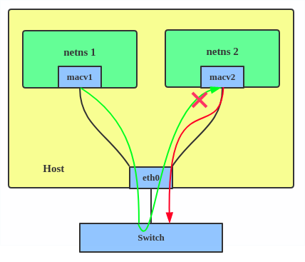
1. Private: doesn’t allow communication between MACVLAN instances on the same physical interface, even if the external switch supports hairpin mode.
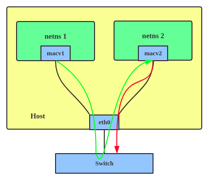
2. VEPA: data from one MACVLAN instance to the other on the same physical interface is transmitted over the physical interface. Either the attached switch needs to support hairpin mode or there must be a TCP/IP router forwarding the packets in order to allow communication.
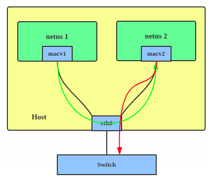
3. Bridge: all endpoints are directly connected to each other with a simple bridge via the physical interface.
4. Passthru: allows a single VM to be connected directly to the physical interface.
5. Source: the source mode is used to filter traffic based on a list of allowed source MAC addresses to create MAC-based VLAN associations. Please see the commit message.
The type is chosen according to different needs. Bridge mode is the most commonly used.
Use a MACVLAN when you want to connect directly to a physical network from containers.
Here’s how to set up a MACVLAN:
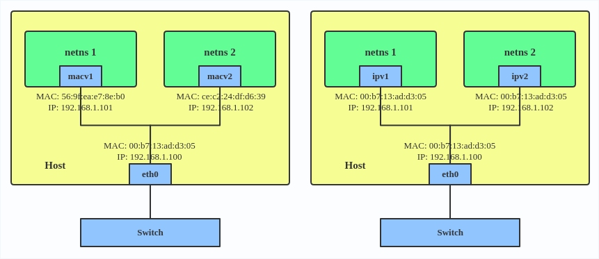
This creates two new MACVLAN devices in bridge mode and assigns these two devices to two different namespaces.
IPVLAN
IPVLAN is similar to MACVLAN with the difference being that the endpoints have the same MAC address.
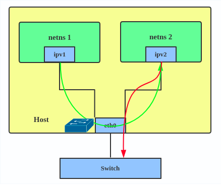
IPVLAN supports L2 and L3 mode. IPVLAN L2 mode acts like a MACVLAN in bridge mode. The parent interface looks like a bridge or switch.
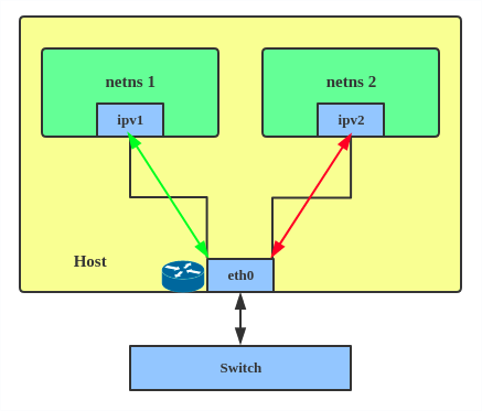
In IPVLAN L3 mode, the parent interface acts like a router and packets are routed between endpoints, which gives better scalability.
Regarding when to use an IPVLAN, the IPVLAN kernel documentation says that MACVLAN and IPVLAN «are very similar in many regards and the specific use case could very well define which device to choose. if one of the following situations defines your use case then you can choose to use ipvlan —
(a) The Linux host that is connected to the external switch / router has policy configured that allows only one mac per port.
(b) No of virtual devices created on a master exceed the mac capacity and puts the NIC in promiscuous mode and degraded performance is a concern.
(c) If the slave device is to be put into the hostile / untrusted network namespace where L2 on the slave could be changed / misused.»
Here’s how to set up an IPVLAN instance:
This creates an IPVLAN device named ipvl0 with mode L2, assigned to namespace ns0 .
MACVTAP/IPVTAP
MACVTAP/IPVTAP is a new device driver meant to simplify virtualized bridged networking. When a MACVTAP/IPVTAP instance is created on top of a physical interface, the kernel also creates a character device/dev/tapX to be used just like a TUN/TAP device, which can be directly used by KVM/QEMU.
With MACVTAP/IPVTAP, you can replace the combination of TUN/TAP and bridge drivers with a single module:
Typically, MACVLAN/IPVLAN is used to make both the guest and the host show up directly on the switch to which the host is connected. The difference between MACVTAP and IPVTAP is same as with MACVLAN/IPVLAN.
Here’s how to create a MACVTAP instance:
MACsec
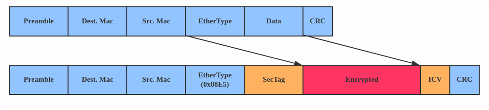
MACsec (Media Access Control Security) is an IEEE standard for security in wired Ethernet LANs. Similar to IPsec, as a layer 2 specification, MACsec can protect not only IP traffic but also ARP, neighbor discovery, and DHCP. The MACsec headers look like this:
The main use case for MACsec is to secure all messages on a standard LAN including ARP, NS, and DHCP messages.
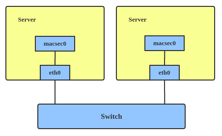
Here’s how to set up a MACsec configuration:
Note: This only adds a MACsec device called macsec0 on interface eth1 . For more detailed configurations, please see the «Configuration example» section in this MACsec introduction by Sabrina Dubroca.
The VETH (virtual Ethernet) device is a local Ethernet tunnel. Devices are created in pairs, as shown in the diagram below.
Packets transmitted on one device in the pair are immediately received on the other device. When either device is down, the link state of the pair is down.
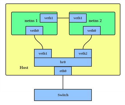
Use a VETH configuration when namespaces need to communicate to the main host namespace or between each other.
Here’s how to set up a VETH configuration:
This creates two namespaces, net1 and net2 , and a pair of VETH devices, and it assigns veth1 to namespace net1 and veth2 to namespace net2 . These two namespaces are connected with this VETH pair. Assign a pair of IP addresses, and you can ping and communicate between the two namespaces.
Similar to the network loopback devices, the VCAN (virtual CAN) driver offers a virtual local CAN (Controller Area Network) interface, so users can send/receive CAN messages via a VCAN interface. CAN is mostly used in the automotive field nowadays.
For more CAN protocol information, please refer to the kernel CAN documentation.
Use a VCAN when you want to test a CAN protocol implementation on the local host.
Here’s how to create a VCAN:
VXCAN
Similar to the VETH driver, a VXCAN (Virtual CAN tunnel) implements a local CAN traffic tunnel between two VCAN network devices. When you create a VXCAN instance, two VXCAN devices are created as a pair. When one end receives the packet, the packet appears on the device’s pair and vice versa. VXCAN can be used for cross-namespace communication.
Use a VXCAN configuration when you want to send CAN message across namespaces.
Here’s how to set up a VXCAN instance:
Note: VXCAN is not yet supported in Red Hat Enterprise Linux.
IPOIB
An IPOIB device supports the IP-over-InfiniBand protocol. This transports IP packets over InfiniBand (IB) so you can use your IB device as a fast NIC.
The IPoIB driver supports two modes of operation: datagram and connected. In datagram mode, the IB UD (Unreliable Datagram) transport is used. In connected mode, the IB RC (Reliable Connected) transport is used. The connected mode takes advantage of the connected nature of the IB transport and allows an MTU up to the maximal IP packet size of 64K.
For more details, please see the IPOIB kernel documentation.
Use an IPOIB device when you have an IB device and want to communicate with a remote host via IP.
Here’s how to create an IPOIB device:
NLMON
NLMON is a Netlink monitor device.
Use an NLMON device when you want to monitor system Netlink messages.
Here’s how to create an NLMON device:
This creates an NLMON device named nlmon0 and sets it up. Use a packet sniffer (for example, tcpdump ) to capture Netlink messages. Recent versions of Wireshark feature decoding of Netlink messages.
Dummy interface
A dummy interface is entirely virtual like, for example, the loopback interface. The purpose of a dummy interface is to provide a device to route packets through without actually transmitting them.
Use a dummy interface to make an inactive SLIP (Serial Line Internet Protocol) address look like a real address for local programs. Nowadays, a dummy interface is mostly used for testing and debugging.
Here’s how to create a dummy interface:
The IFB (Intermediate Functional Block) driver supplies a device that allows the concentration of traffic from several sources and the shaping incoming traffic instead of dropping it.
Use an IFB interface when you want to queue and shape incoming traffic.
Here’s how to create an IFB interface:
This creates an IFB device named ifb0 and replaces the root qdisc scheduler with SFQ (Stochastic Fairness Queueing), which is a classless queueing scheduler. Then it adds an ingress qdisc scheduler on eth0 and redirects all ingress traffic to ifb0 .
For more IFB qdisc use cases, please refer to this Linux Foundation wiki on IFB.
Additional resources
- Virtual networking articles on the Red Hat Developer blog
- Dynamic IP Address Management in Open Virtual Network (OVN)
- Non-root Open vSwitch in Red Hat Enterprise Linux
- Open vSwitch articles on the Red hat Developer Blog
netdevsim interface
netdevsim is a simulated networking device which is used for testing various networking APIs. At this time it is particularly focused on testing hardware
offloading, tc/XDP BPF and SR-IOV.
A netdevsim device can be created as follows
To enable tc offload:
To load XDP BPF or tc BPF programs:
To add VFs for SR-IOV testing:
To change the vf numbers, you need to disable them completely first:
Note : netdevsim is not compiled in RHEL by default
Источник


