- USB host-side drivers in Windows
- USB 3.0 driver stack
- USB 3.0 host controller driver (Usbxhci.sys)
- USB host controller extension (Ucx01000.sys)
- USB hub driver (Usbhub3.sys)
- USB 2.0 driver stack
- USB common class generic parent driver (Usbccgp.sys)
- WinUSB (Winusb.sys)
- USB client driver
- Helper libraries for client drivers
- How to write your first USB client driver (UMDF)
- Prerequisites
- Software requirements
- Hardware requirements
- Recommended reading
- Instructions
- Step 1: Generate the UMDF driver code by using the Visual StudioВ 2019 USB driver template
- For USB-specific code, select the following options in Visual StudioВ 2019
- Step 2: Modify the INF file to add information about your device
- To provide the hardware ID string
- Step 3: Build the USB client driver code
- Step 4: Configure a computer for testing and debugging
- Step 5: Enable tracing for kernel debugging
- To configure your host computer for WPP tracing
- To configure your target computer for WPP tracing
- Step 6: Deploy the driver on the target computer
- Step 7: View the driver in Device Manager
- Step 8: View the output in the debugger
- Remarks
USB host-side drivers in Windows
This topic provides an overview of the Universal Serial Bus (USB) driver stack architecture.
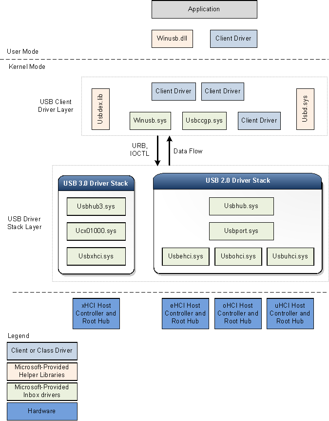
The following figure shows the architectural block diagram of the USB driver stack for WindowsВ 8. The diagram shows separate USB driver stacks for USB 2.0 and USB 3.0. Windows loads the USB 3.0 driver stack when a device is attached to an xHCI controller. The USB 3.0 stack is new in WindowsВ 8.
Windows loads the USB 2.0 driver stack for devices that are attached to eHCI, oHCI, or uHCI controllers. The USB 2.0 driver stack ships in WindowsВ XP with Service PackВ 1 (SP1) and later versions of the Windows operating system.
USB 3.0 driver stack
The USB 3.0 stack is new in WindowsВ 8. Microsoft created the new drivers by using Kernel Mode Driver Framework (KMDF) interfaces. The KMDF driver model reduces complexity and improves stability.
USB 3.0 host controller driver (Usbxhci.sys)
The xHCI driver is the USB 3.0 host controller driver. The responsibilities of the xHCI driver include initializing MMIO registers and host memory-based data structures for xHCI controller hardware, mapping transfer requests from upper layer drivers to Transfer Request Blocks, and submitting the requests to the hardware. After completing a transfer, the driver handles transfer completion events from the hardware and propagates the events up the driver stack. It also controls the xHCI controller device slots and endpoint contexts.
The xHCI driver is new in WindowsВ 8 and is not an extension of the eHCI miniport driver that was available in earlier versions of the operating system. The new driver was written by using Kernel Mode Driver Framework (KMDF) interfaces and uses KMDF for all controller power management and PnP events. Windows loads the xHCI driver as the function device object (FDO) in the device stack for the host controller.
USB host controller extension (Ucx01000.sys)
The USB host controller extension driver (an extension to KMDF) is the new extension to the underlying class-specific host controller driver, such as the xHCI driver. The new driver is extensible and is designed to support other types of host controller drivers that are expected to be developed in the future. The USB host controller extension serves as a common abstracted interface to the hub driver, provides a generic mechanism for queuing requests to the host controller driver, and overrides certain selected functions. All I/O requests initiated by upper drivers reach the host controller extension driver before the xHCI driver. Upon receiving an I/O request, the host controller extension validates the request and then forwards the request to the proper KMDF queue associated with the target endpoint. The xHCI driver, when ready for processing, retrieves the request from the queue. The responsibilities of the USB host controller extension driver are:
- Provides USB-specific objects to the xHCI driver.
- Provides KMDF event callback routines to the xHCI driver.
- Manages and control the operations of the root hub associated with the host controller.
- Implements features that are configurable by the client driver, like chained MDLs, streams, and so on.
USB hub driver (Usbhub3.sys)
The new hub driver, in the USB driver stack for 3.0 devices, uses the KMDF driver model. The hub driver primarily performs these tasks:
- Manages USB hubs and their ports.
- Enumerates devices and other hubs attached to their downstream ports.
- Creates physical device objects (PDOs) for the enumerated devices and hubs.
Windows loads the hub driver as the FDO in the hub device stack. Device enumeration and hub management in the new driver are implemented through a set of state machines. The hub driver relies on KMDF for power management and PnP functions. In addition to hub management, the hub driver also performs preliminary checks and processing of certain requests sent by the USB client driver layer. For instance, the hub driver parses a select-configuration request to determine which endpoints will be configured by the request. After parsing the information, the hub driver submits the request to the USB host controller extension or further processing.
USB 2.0 driver stack
Windows loads the USB 2.0 driver stack for devices that are attached to eHCI, oHCI, or uHCI controllers. The drivers in the USB 2.0 driver stack ship in WindowsВ XP with SP1 and later versions of the Windows operating system. The USB 2.0 driver stack is designed to facilitate high-speed USB devices as defined in the USB 2.0 specification.
At the bottom of the USB driver stack is the host controller driver. It consists of the port driver, Usbport.sys, and one or more of three miniport drivers that run concurrently. When the system detects host controller hardware, it loads one of these miniport drivers. The miniport driver, after it is loaded, loads the port driver, Usbport.sys. The port driver handles those aspects of the host controller driver’s duties that are independent of the specific protocol.
The Usbuhci.sys (universal host controller interface) miniport driver replaces the Uhcd.sys miniclass driver that shipped with WindowsВ 2000. The Usbohci.sys (open host controller interface) miniport driver replaces Openhci.sys. The Usbehci.sys miniport driver supports high-speed USB devices and was introduced in WindowsВ XP with SP1 and later and Windows ServerВ 2003 and later operating systems.
In all versions of Windows that support USB 2.0, the operating system is capable of managing USB 1.1 and USB 2.0 host controllers simultaneously. Whenever the operating system detects that both types of controller are present, it creates two separate device nodes, one for each host controller. Windows subsequently loads the Usbehci.sys miniport driver for the USB 2.0-compliant host controller hardware and either Usbohci.sys or Openhci.sys for the USB 1.1-compliant hardware, depending on the system configuration.
Above the port driver is the USB bus driver, Usbhub.sys, also known as the hub driver. This is the device driver for each hub on the system.
USB common class generic parent driver (Usbccgp.sys)
The USB common class generic parent driver is the Microsoft-provided parent driver for composite devices. The hub driver enumerates and loads the parent composite driver if deviceClass is 0 or 0xef and numInterfaces is greater than 1 in the device descriptor. The hub driver generates the compatible ID for the parent composite driver as «USB\COMPOSITE». Usbccgp.sys uses Windows Driver Model (WDM) routines.
The parent composite driver enumerates all functions in a composite device and creates a PDO for each one. This causes the appropriate class or client driver to be loaded for each function in the device. Each function driver (child PDO) sends requests to the parent driver, which submits them to the USB hub driver.
Usbccgp.sys is included with WindowsВ XP with SP1 and later versions of the Windows operating system. In WindowsВ 8, the driver has been updated to implement function suspend and remote wake-up features as defined in the USB 3.0 specification.
WinUSB (Winusb.sys)
Windows USB (WinUSB) is a Microsoft-provided generic driver for USB devices. WinUSB architecture consists of a kernel-mode driver (Winusb.sys) and a user-mode dynamic link library (Winusb.dll). For devices that don’t require a custom function driver, Winusb.sys can be installed in the device’s kernel-mode stack as the function driver. User-mode processes can then communicate with Winusb.sys by using a set of device I/O control requests or by calling WinUsb_Xxx functions. For more information, see WinUSB.
In WindowsВ 8, the Microsoft-provided information (INF) file for WinUSB, Winusb.inf, contains USB\MS_COMP_WINUSB as a device identifier string. This allows Winusb.sys to get automatically loaded as the function driver for those devices that have a matching WinUSB compatible ID in the MS OS descriptor. Such devices are called WinUSB devices. Hardware manufacturers are not required to distribute an INF file for their WinUSB device, making the driver installation process simpler for the end user. For more information, see WinUSB Device.
USB client driver
Each USB device, composite or non-composite, is managed by a client driver. A USB client driver is a class or device driver that is a client of the USB driver stack. Such drivers include class and device-specific drivers from Microsoft or a third-party vendor. To see a list of class drivers provided by Microsoft, see Drivers for the Supported USB Device Classes. A client driver creates requests to communicate with the device by calling public interfaces exposed by the USB driver stack.
A client driver for a composite device is no different from a client driver for a non-composite device, except for its location in the driver stack.
A client driver for a non-composite device is layered directly above the hub driver.
For a composite USB device that exposes multiple functions and does not have a parent class driver, Windows loads the USB generic parent driver (Usbccgp.sys) between the hub driver and the client driver layer. The parent driver creates a separate PDO for each function of a composite device. Client drivers (FDOs for functions) are loaded above the generic parent driver. Vendors might choose to provide a separate client driver for each function.
A USB client driver can run in either user mode or kernel mode, depending on the requirements of the driver. USB client drivers can be written by using KMDF, UMDF, or WDM routines.
Helper libraries for client drivers
Microsoft provides the following helper libraries to help kernel-mode drivers and applications to communicate with the USB driver stack:
How to write your first USB client driver (UMDF)
In this topic you’ll use the USB User-Mode Driver template provided with Microsoft Visual StudioВ 2019 to write a user-mode driver framework (UMDF)-based client driver. After building and installing the client driver, you’ll view the client driver in Device Manager and view the driver output in a debugger.
UMDF (referred to as the framework in this topic) is based on the component object model (COM). Every framework object must implement IUnknown and its methods, QueryInterface, AddRef, and Release, by default. The AddRef and Release methods manage the object’s lifetime, so the client driver does not need to maintain the reference count. The QueryInterface method enables the client driver to get interface pointers to other framework objects in the Windows Driver Frameworks (WDF) object model. Framework objects perform complicated driver tasks and interact with Windows. Certain framework objects expose interfaces that enable a client driver to interact with the framework.
A UMDF-based client driver is implemented as an in-process COM server (DLL), and C++ is the preferred language for writing a client driver for a USB device. Typically, the client driver implements several interfaces exposed by the framework. This topic refers to a client driver-defined class that implements framework interfaces as a callback class. After these classes are instantiated, the resulting callback objects are partnered with particular framework objects. This partnership gives the client driver the opportunity to respond to device or system-related events that are reported by the framework. Whenever Windows notifies the framework about certain events, the framework invokes the client driver’s callback, if one is available. Otherwise the framework proceeds with the default processing of the event. The template code defines driver, device, and queue callback classes.
For an explanation about the source code generated by the template, see Understanding the UMDF template code for USB client driver.
Prerequisites
For developing, debugging, and installing a user-mode driver, you need two computers:
- A host computer running WindowsВ 7 or a later version of the Windows operating system. The host computer is your development environment, where you write and debug your driver.
- A target computer running the version of the operating system that you want to test your driver on, for example, Windows 10, version 1903. The target computer has the user-mode driver that you want to debug and one of the debuggers.
In some cases, where the host and target computers are running the same version of Windows, you can have just one computer running Windows 7 or a later version of the Windows. This topic assumes that you are using two computers for developing, debugging, and installing your user mode driver.
Before you begin, make sure that you meet the following requirements:
Software requirements
Your host computer has Visual StudioВ 2019.
Your host computer has the latest Windows Driver Kit (WDK) for Windows 10, version 1903.
The kit include headers, libraries, tools, documentation, and the debugging tools required to develop, build, and debug a USB client driver. You can get the latest version of the WDK from How to Get the WDK.
Your host computer has the latest version of debugging tools for Windows. You can get the latest version from the WDK or you can Download and Install Debugging Tools for Windows.
If you are using two computers, you must configure the host and target computers for user-mode debugging. For more information, see Setting Up User-Mode Debugging in Visual Studio.
Hardware requirements
Get a USB device for which you will be writing the client driver. In most cases, you are provided with a USB device and its hardware specification. The specification describes device capabilities and the supported vendor commands. Use the specification to determine the functionality of the USB driver and the related design decisions.
If you are new to USB driver development, use the OSR USB FX2 learning kit to study USB samples included with the WDK. It contains the USB FX2 device and all the required hardware specifications to implement a client driver.
Recommended reading
- Concepts for All Driver Developers
- Device nodes and device stacks
- Getting started with Windows drivers
- User-Mode Driver Framework
- Developing Drivers with Windows Driver Foundation, written by Penny Orwick and Guy Smith. For more information, see Developing Drivers with WDF.
Instructions
Step 1: Generate the UMDF driver code by using the Visual StudioВ 2019 USB driver template
For instructions about generating UMDF driver code, see Writing a UMDF driver based on a template.
For USB-specific code, select the following options in Visual StudioВ 2019
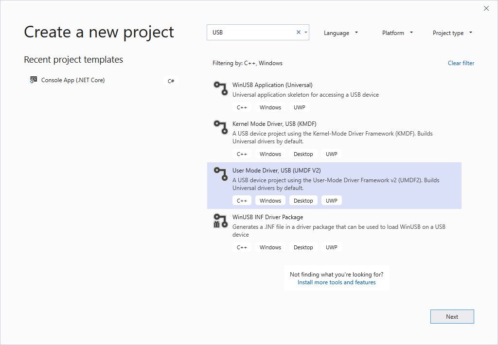
- In the New Project dialog box, in the search box at the top, type USB.
- n the middle pane, select User Mode Driver, USB (UMDF V2).
- lick Next.
- Enter a project name, choose a save location, and click Create.
The following screen shots show the New Project dialog box for the USB User-Mode Driver template.

This topic assumes that the name of the project is «MyUSBDriver_UMDF_». It contains the following files:
| Files | Description |
|---|---|
| Driver.h; Driver.c | Declares and defines a callback class that implements the IDriverEntry interface. The class defines methods that are invoked by the framework driver object. The main purpose of this class is to create a device object for the client driver. |
| Device.h; Device.c | Declares and defines a callback class that implements the IPnpCallbackHardware interface. The class defines methods that are invoked by the framework device object. The main purpose of this class is to handle events occurring as a result of Plug and Play (PnP) state changes. The class also allocates and initializes resources required by the client driver as long as it is loaded in the system. |
| IoQueue.h; IoQueue.c | Declares and defines a callback class that implements the IQueueCallbackDeviceIoControl interface. The class defines methods that are invoked by the framework queue object. The purpose of this class is to retrieve I/O requests that are queued in the framework. |
| Internal.h | Provides common declarations shared by the client driver and user applications that communicate with the USB device. It also declares tracing functions and macros. |
| Dllsup.cpp | Contains the implementation of the driver module’s entry point. |
| .inf | INF file that is required to install the client driver on the target computer. |
| Exports.def | DEF file that exports the entry point function name of the driver module. |
Step 2: Modify the INF file to add information about your device
Before you build the driver, you must modify the template INF file with information about your device, specifically the hardware ID string.
To provide the hardware ID string
Attach your USB device to your host computer and let Windows enumerate the device.
Open Device Manager and open properties for your device.
On the Details tab, select Hardward Ids under Property.
The hardware ID for the device is displayed in the list box. Select and hold (or right-click) and copy the hardware ID string.
In Solution Explorer, expand Driver Files, and open the INF.
Replace the following your hardware ID string.
Notice the AddReg entries in the driver’s information (INF) file.
- WudfCoinstaller.dll (configuration co-installer)
- WUDFUpdate_ .dll (redistributable co-installer)
- Wdfcoinstaller .dll (co-installers for KMDF)
- Winusbcoinstaller2.dll ((co-installers for Winusb.sys)
- MyUSBDriver_UMDF_.dll (client driver module)
If your INF AddReg directive references the UMDF redistributable co-installer (WUDFUpdate_ .dll ), you must not make a reference to the configuration co-installer (WUDFCoInstaller.dll). Referencing both co-installers in the INF will lead to installation errors.
All UMDF-based USB client drivers require two Microsoft-provided drivers: the reflector and WinUSB.
Reflector—If your driver gets loaded successfully, the reflector is loaded as the top-most driver in the kernel-mode stack. The reflector must be the top driver in the kernel mode stack. To meet this requirement, the template’s INF file specifies the reflector as a service and WinUSB as a lower-filter driver in the INF:
AddService=WUDFRd,0x000001fa,WUDFRD_ServiceInstall ; flag 0x2 sets this as the service for the device
AddService=WinUsb,0x000001f8,WinUsb_ServiceInstall ; this service is installed because its a filter.
WinUSB—The installation package must contain coinstallers for Winusb.sys because for the client driver, WinUSB is the gateway to the kernel-mode USB driver stack. Another component that gets loaded is a user-mode DLL, named WinUsb.dll, in the client driver’s host process (Wudfhost.exe). Winusb.dll exposes WinUSB Functions that simplify the communication process between the client driver and WinUSB.
Step 3: Build the USB client driver code
To build your driver
- Open the driver project or solution in Visual StudioВ 2019.
- Right-click the solution in the Solution Explorer and select Configuration Manager.
- From the Configuration Manager, select your Active Solution Configuration (for example, Debug or Release) and your Active Solution Platform (for example, Win32) that correspond to the type of build you are interested in.
- Verify that your device interface GUID is accurate throughout the project.
- The device interface GUID is defined in Trace.h and is referenced from MyUSBDriverUMDFCreateDevice in Device.c. When you create your project with the name «MyUSBDriver_UMDF_», Visual Studio 2019 defines the device interface GUID with the name GUID_DEVINTERFACE_MyUSBDriver_UMDF_ but calls WdfDeviceCreateDeviceInterface with the incorrect parameter «GUID_DEVINTERFACE_MyUSBDriverUMDF». Replace the incorrect parameter with the name defined in Trace.h to ensure that the driver builds properly.
- From the Build menu, click Build Solution.
For more information, see Building a Driver.
Step 4: Configure a computer for testing and debugging
To test and debug a driver, you run the debugger on the host computer and the driver on the target computer. So far, you have used Visual Studio on the host computer to build a driver. Next you need to configure a target computer. To configure a target computer, follow the instructions in Provision a computer for driver deployment and testing.
Step 5: Enable tracing for kernel debugging
The template code contains several trace messages (TraceEvents) that can help you track function calls. All functions in the source code contain trace messages that mark the entry and exit of a routine. For errors, the trace message contains the error code and a meaningful string. Because WPP tracing is enabled for your driver project, the PDB symbol file created during the build process contains trace message formatting instructions. If you configure the host and target computers for WPP tracing, your driver can send trace messages to a file or the debugger.
To configure your host computer for WPP tracing
Create trace message format (TMF) files by extracting trace message formatting instructions from the PDB symbol file.
You can use Tracepdb.exe to create TMF files. The tool is located in the Windows Kits\10\bin\ folder of the WDK. The following command creates TMF files for the driver project.
tracepdb -f [PDBFiles] -p [TMFDirectory]
The -f option specifies the location and the name of the PDB symbol file. The -p option specifies the location for the TMF files that are created by Tracepdb. For more information, see Tracepdb Commands.
At the specified location you’ll see three files (one per .c file in the project). They are given GUID file names.
In the debugger, type the following commands:
- Load the Wmitrace.dll extension.
- Verfies that the debugger extension is loaded.
- Adds the location of the TMF files to the debugger extension’s search path.
The output resembles this:
To configure your target computer for WPP tracing
- Make sure you have the Tracelog tool on your target computer. The tool is located in the Windows Kits\10\Tools\ folder of the WDK. For more information, see Tracelog Command Syntax.
- Open a Command Window and run as administrator.
- Type the following command:
The command starts a trace session named MyTrace.
The guid argument specifies the GUID of the trace provider, which is the client driver. You can get the GUID from Trace.h in the Visual Studio 2019 project. As another option, you can type the following command and specify the GUID in a .guid file. The file contains the GUID in hyphen format:
You can stop the trace session by typing the following command:
Step 6: Deploy the driver on the target computer
- In the Solution Explorer window, select and hold (or right-click) the
Package , and choose Properties.
Do not specify the hardware ID of your device under Hardware ID Driver Update. The hardware ID must be specified only in your driver’s information (INF) file.
Step 7: View the driver in Device Manager
Enter the following command to open Device Manager.
devmgmt
Verify that Device Manager shows the following node.
USB Device
MyUSBDriver_UMDF_Device
Step 8: View the output in the debugger
Verify that trace messages appear in the Debugger Immediate Window on the host computer.
The output should be similar to the following:
Remarks
Let’s take a look at how the framework and the client driver work together to interact with Windows and handle requests sent to the USB device. This illustration shows the modules loaded in the system for a UMDF -based USB client driver.
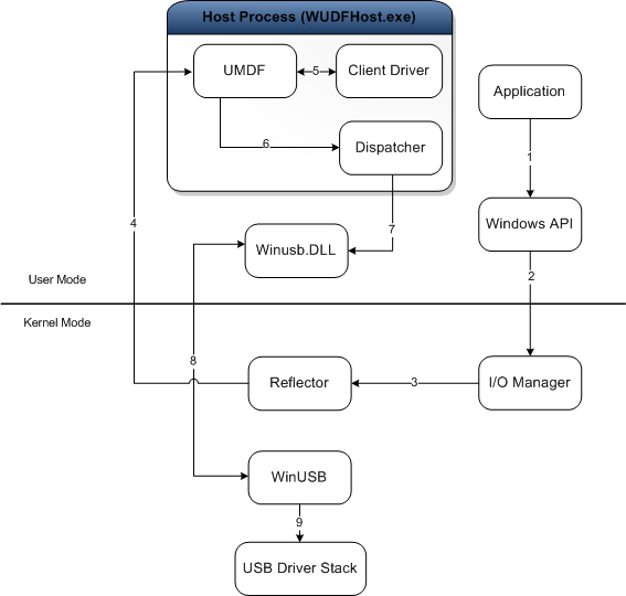
The purpose of each module is described here:
- Application—a user-mode process that issues I/O requests to communicate with the USB device.
- I/O Manager—a Windows component that creates I/O request packets (IRPs) to represent the received application requests, and forwards them to the top of the kernel-mode device stack for the target device.
- Reflector—a Microsoft-provided kernel-mode driver installed at the top of the kernel-mode device stack (WUDFRd.sys). The reflector redirects IRPs received from the I/O manager to the client driver host process. Upon receiving the request, the framework and the client driver handle the request.
- Host process —the process in which the user-mode driver runs (Wudfhost.exe). It also hosts the framework and the I/O dispatcher.
- Client driver—the user-mode function driver for the USB device.
- UMDF—the framework module that handles most interactions with Windows on the behalf of the client driver. It exposes the user-mode device driver interfaces (DDIs) that the client driver can use to perform common driver tasks.
- Dispatcher—mechanism that runs in the host process; determines how to forward a request to the kernel mode after it has been processed by user-mode drivers and has reached the bottom of the user-mode stack. In the illustration, the dispatcher forwards the request to the user-mode DLL, Winusb.dll.
- Winusb.dll—a Microsoft-provided user-mode DLL that exposes WinUSB Functions that simplify the communication process between the client driver and WinUSB (Winusb.sys, loaded in kernel mode).
- Winusb.sys—a Microsoft-provided driver that is required by all UMDF client drivers for USB devices. The driver must be installed below the reflector and acts as the gateway to the USB driver stack in the kernel-mode. For more information, see WinUSB.
- USB driver stack—a set of drivers, provided by Microsoft, that handle protocol-level communication with the USB device. For more information, see USB host-side drivers in Windows.
Whenever an application makes a request for the USB driver stack, the Windows I/O manager sends the request to the reflector, which directs it to client driver in user mode. The client driver handles the request by calling specific UMDF methods, which internally call WinUSB Functions to send the request to WinUSB. Upon receiving the request, WinUSB either processes the request or forwards it to the USB driver stack.


