Handling IRP_MN_SET_POWER for System Power States
The power manager sends a power IRP that specifies the minor code IRP_MN_SET_POWER and a system power state for one of the following reasons:
To change the system power state.
To reaffirm the current power state after a failed IRP_MN_QUERY_POWER request.
Through the I/O manager, the power manager sends the IRP to the top driver in the device stack at each PnP device node. The IRP notifies all drivers in the stack of the correct system power state.
To ensure an orderly start-up, the power manager sequences system power-up IRPs so that parent devices have the opportunity to power up before their children do. The power manager does not query before sending a system power-up IRP.
Similarly, to ensure that the computer sleeps or shuts down in an orderly way, the power manager sends system IRPs that specify sleep, hibernation, or shutdown in a defined sequence, so that devices farther from the root power down before devices nearer the root. Whenever possible, the power manager queries before sending such an IRP. For more information, see Handling IRP_MN_QUERY_POWER for System Power States.
The system power IRP is not a direct request to change power state — it is a notification. A driver must not change the power state of its device as a direct response to the system power IRP; a driver changes its device’s power state only in response to a device power IRP. (The device power policy owner sends the device power IRP; see Handling a System Set-Power IRP in a Device Power Policy Owner.)
Even if the device is already in a device power state that is valid for the requested system power state, each driver must nevertheless pass the system set-power IRP to the next-lower driver, until it reaches the bus driver. Only the bus driver is allowed to complete this IRP.
How a driver handles this IRP depends upon its role in the device stack, as described in the following sections:
A driver cannot fail an IRP_MN_SET_POWER request to set the system power state. The power manager ignores any failure status returned for this IRP.
System Power States
System power states describe the power consumption of the system as a whole. The operating system supports six system power states, referred to as S0 (fully on and operational) through S5 (power off). Each state is characterized by the following:
Power consumption: how much power does the computer use?
Software resumption: from what point does the operating system restart?
Hardware latency: how long does it take to return the computer to the working state?
System hardware context (such as the content of volatile processor registers, memory caches, and RAM): how much system hardware context is retained? Must the operating system reboot to return to the working state?
State S0 is the working state. States S1, S2, S3, and S4 are sleeping states, in which the computer appears off because of reduced power consumption but retains enough context to return to the working state without restarting the operating system. State S5 is the shutdown or off state.
A system is waking when it is in transition from the shutdown state (S5) or any sleeping state (S1-S4) to the working state (S0), and it is going to sleep when it is in transition from the working state to any sleep state or the shutdown state. The following figure shows the possible system power state transitions.
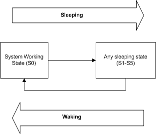
As the previous figure shows, the system cannot enter one sleep state directly from another; it must always enter the working state before entering any sleep state. For example, a system cannot transition from state S2 to S4, nor from state S4 to S2. It must first return to S0, from which it can enter the next sleep state. Because a system in an intermediate sleep state has already lost some operating context, it must return to the working state to restore that context before it can make an additional state transition.
Device Power States
A device power state describes the power state of a device in a computer, independently of the other devices in the computer. Device power states are named D0, D1, D2, and D3. D0 is the fully on state, and D1, D2, and D3 are low-power states. The state number is inversely related to power consumption: higher numbered states use less power. Starting with WindowsВ 8, the D3 state is divided into two substates, D3hot and D3cold.
Device power states are characterized by the following attributes:
Power consumption: How much power does the device use?
Device context: How much of its operational context does the device retain in this state?
Device driver behavior: What must the drivers for the device do to restore the device to the fully operational state?
Restore time: How long does it take to restore the device to the fully operational state? Most types of devices have modest restore times that differ little from one device class to the next. Only a few types of devices, such as GPUs, have very large hardware contexts that take significantly longer to restore.
Wake-up capability: Can the device request wake-up from this state? In general, if a device can request wake-up from a given power state (for example, D2), it can also request wake-up from any higher-powered state (D1).
The exact definitions of the power states are device-specific. Not all devices define all the states; many devices define only the D0 and D3 states. See the Device Class Power Management Reference Specification to find out which device power states are defined for a specific device and what the operational requirements are for each state. (The reference specifications are available at the ACPI / Power Management website.)
The power state of a device need not match the system power state. For example, some devices can be in the off (D3) state even though the system is in the system working state (S0).
The power state of a device might seem to be unrelated to the power state of the device’s parent bus. For example, a USB device might be in the D2 (selective suspend) state when its parent host controller is in the D3 state. These two states appear to be inconsistent only because the definitions of the Dx states are different on USB and on the bus (typically PCI or PCI Express) that the USB host controller is connected to.
Note that some devices are capable of several different low power modes within a single device power state. Such a device can use these modes if its driver can automatically switch the device from one mode to another without changing the device power state. As a general rule, however, if there is no user-perceptible difference between the modes, the device should use only the lowest power mode. If a low power mode, such as a low-speed mode, adversely affects performance or is not transparent to software other than the device driver, the hardware should not automatically use it. See the Device Class Power Management Reference Specification for details.
A driver or the power manager can request a device power state transition, and all drivers must be prepared to handle IRPs that request such transitions. For more information, see the following topics:
Like the system, a device can transition from the working state (D0) to any low-power state (D1, D2, or D3) and from any low-power state to the working state. The following diagram is a state graph that shows the valid device power state transitions.
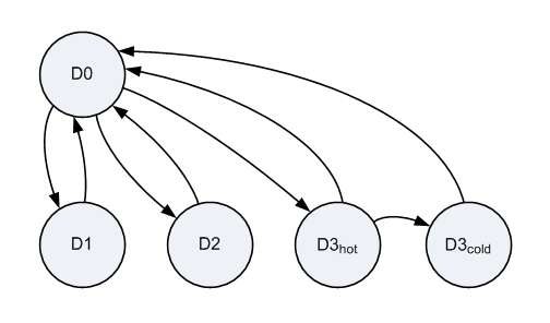
This graph shows the subdivision of D3 into D3hot and D3cold. D3hot and D3cold are defined starting with WindowsВ 8. All devices are required to support the D0 state and D3hot substate. The other states shown in the diagram are optional.
In the preceding graph, the transition from D3hot to D3cold is the only direct transition between device low-power states. All other transitions between low-power states require an intermediate transition to D0, which allows the device driver to configure the device hardware, as required, either to enter the next low-power state or to stay in D0. However, a device exits D3hot and enters D3cold when power to the device is shut off, which requires no intervention from the device driver. This driver does any necessary configuration of the device hardware before the device enters D3hot; no additional configuration is required to prepare the device for the transition from D3hot to D3cold. For more information, see Supporting D3cold in a Driver.
PCI Root Port to endpoint D-state mapping
On Windows 10 systems, the overall platform power state depends on the power states (D-states) of SoC (System on Chip) integrated devices, including the PCI Root Ports. Depending on the platform being developed, the D-state requirements for PCI Root Ports may vary for each platform power state. OEMs are encouraged to refer to the IHV platform-specific documentation for platform and device power state requirements.
The table below enumerates the power state mapping of PCI Root Ports and its attached endpoints. The D-states of endpoints listed below must be achieved in order for the Root Port to enter the target D-state.
| Root Port Target D-State | Endpoint D-State |
|---|---|


