- Using the traceroute Command on Operating Systems
- Available Languages
- Download Options
- Contents
- Introduction
- Prerequisites
- Requirements
- Components Used
- Conventions
- General Operation
- Cisco IOS and Linux
- Microsoft Windows
- ICMP Unreachables Rate Limitation
- Examples
- Cisco Router with Cisco IOS Software
- PC with Linux
- PC with MS Windows
- Additional Notes
- Summary
- Windows traceroute with udp
- 2. Скачайте и установите программу tracetcp
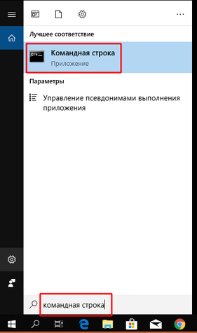
- 3. Откройте командную строку Windows
- 4. Для проверки трассировки до сайта наберите следующую команду:
Using the traceroute Command on Operating Systems
Available Languages
Download Options
Contents
Introduction
The traceroute command allows you to determine the path a packet takes in order to get to a destination from a given source by returning the sequence of hops the packet has traversed. This utility comes with your host operating system (for example, Linux or Microsoft (MS) Windows), as well as with Cisco IOS® Software.
Prerequisites
Requirements
Readers of this document should have basic knowledge of one of these operating systems:
Cisco IOS Software
Components Used
The information in this document applies to these software and hardware versions:
Cisco Router that runs Cisco IOS Software Release 12.2(27)
PC that runs Red Hat Linux version 9
PC that runs MS Windows 2000
The information in this document was created from the devices in a specific lab environment. All of the devices used in this document started with a cleared (default) configuration. If your network is live, make sure that you understand the potential impact of any command.
Conventions
For more information on document conventions, refer to the Cisco Technical Tips Conventions.
General Operation
If you execute the traceroute ip-address command on a source device (such as a host, or a router acting as a host), it sends IP packets toward the destination with Time To Live (TTL) values that increment up to the maximum specified hop count. This is 30 by default. Typically, each router in the path towards the destination decrements the TTL field by one unit while it forwards these packets. When a router in the middle of the path finds a packet with TTL = 1, it responds with an Internet Control Message Protocol (ICMP) «time exceeded» message to the source. This message lets the source know that the packet traverses that particular router as a hop
There are some differences with the way the traceroute command is implemented in the various operating systems this document discusses.
Cisco IOS and Linux
The TTL for the initial User Datagram Protocol (UDP) datagram probe is set to 1 (or the minimum TTL, as specified by user in the extended traceroute command. The destination UDP port of the initial datagram probe is set to 33434 (or as specified in the extended traceroute command output). The extended traceroute command is a variation of the ordinary traceroute command which allows the default values of the parameters used by the traceroute operation such as TTL and destination port number to be modified. For more information on how to use the extended traceroute command, refer to Using the Extended ping and Extended traceroute Commands. The source UDP port of the initial datagram probe is randomized and has logical operator OR with 0x8000 (ensures a minimum source port of 0x8000). These steps illustrate what happens when the UDP datagram is launched:
Note: The parameters are configurable. This example starts with n = 1 and finishes with n = 3.
The UDP datagram is dispatched with TTL = 1, destination UDP port= 33434, and the source port randomized.
The UDP destination port is incremented, the source UDP port is randomized, and the second datagram dispatched.
Step 2 is repeated for up to three probes (or as many times as requested in an extended traceroute command output). For each of the probes sent, you receive a «TTL exceeded» message, which is used to build a step-by-step path to the destination host.
TTL is incremented, and this cycle repeats with incremental destination port numbers, if the ICMP «time exceeded» message is received. You can also get one of these messages:
An ICMP type 3, code 3 («destination unreachable,» «port unreachable») message, which indicates that a host has been reached.
A «host unreachable,» «net unreachable,» «maximum TTL exceeded,» or a «timeout» type of message, which means that the probe is resent.
Cisco routers send UDP probe packets with a random source port and an incremental destination port (to distinguish the different probes). Cisco routers send the ICMP message «time exceeded» back to the source from where the UDP/ICMP packet was received.
The Linux traceroute command is similar to the Cisco router implementation. However, it uses a fixed source port. The -n option in the traceroute command is used to avoid a request to a name server.
Microsoft Windows
The MS Windows tracert command uses ICMP echo request datagrams instead of UDP datagrams as probes. ICMP echo requests are launched with incrementing TTL, and the same operation as described in Cisco IOS and Linux occurs. The significance of using ICMP echo request datagrams is that the final hop does not rely on the response of an ICMP «unreachable» message from the destination host. It relies instead on an ICMP echo reply message.
The command syntax is:
This table explains the command parameters:
| Parameter | Description |
|---|---|
| -d | Specifies not to resolve addresses to computer names. |
| -h maximum_hops | Specifies the maximum number of hops to search for a target. |
| -j computer-list | Specifies a loose source route along computer-list. |
| -w timeout | Waits the number of milliseconds specified by the timeout for each reply. |
| target_name | Name of the target computer. |
ICMP Unreachables Rate Limitation
ICMP unreachables are limited to one packet per 500 ms (as a protection for Denial of Service (DoS) attacks) in a Cisco Router. From Cisco IOS Software Release 12.1 and later, this rate value is configurable. The command introduced is:
Refer to Cisco bug ID CSCdp28161 (registered customers only) for further details.
This limitation is for the aggregate rate of all the ICMP unreachables, as this output shows. Refer to RFC 792 for more information.
This limitation does not affect other packets like ICMP echo requests or ICMP «time exceeded» messages.
Examples
This network topology is used for the examples:
In each of the three examples, a different Device A is used. From Device A, the traceroute 150.1.4.2 command is executed to Device 7C.
In each of the examples, the debug ip packet detail command runs on Device 11A.
Cisco Router with Cisco IOS Software
This extended traceroute command example shows the options you can change when you execute a traceroute command from a Cisco router. In this example, everything is left default:
In this debug output, Device 11A sends ICMP «time exceeded» messages to the source of the probes (150.1.1.1). These ICMP messages are in response to the initial probes that had a TTL=1. Device 11A decrements the TTL to zero, and responds with the «time exceeded» messages.
Note: You do not see the UDP probes in this debug output for two reasons:
Device 11A is not the destination of the UDP probes.
The TTL is decremented to zero, and the packet is never routed. Therefore, the debug never recognizes the packet.
This debug output shows the UDP probe from source 150.1.1.1 destined to 150.1.4.2.
Note: In these probes the TTL=2 (this cannot be seen with debug). Device 11A decrements the TTL to 1 and forwards the UDP packets onto Device 7A. Device 7A decrements the TTL to zero, and responds with ICMP «time exceeded» messages.
You see the next three UDP probes in this debug output. The TTL for these probes is 3. Device 11A decrements the TTL to 2 and forwards them on to Device 7A. Device 7A decrements the TTL to 1 and forwards the packets on to Device 7B, which decrements the TTL to zero and responds with ICMP «time exceeded» messages.
You can see the last three UDP probes in this debug output. The original TTL of these probes was 4. The TTL was decremented to 3 by Device 11A, then decremented to 2 by Device 7A, then decremented to 1 by Device 7B. Device 7C responds with ICMP «port unreachable» messages, since it was the destination of the probes.
Note: Device 7C only sends two ICMP «port unreachable» messages because of the rate limitation.
PC with Linux
In this debug output, Device 11A sends ICMP «time exceeded» messages to the source of the probes (150.1.1.1). These ICMP messages are in response to the initial probes that had a TTL=1. Device 11A decrements the TTL to zero, and responds with the «time exceeded» messages.
Note: You do not see the UDP probes in this debug output for two reasons:
Device 11A is not the destination of the UDP probes.
The TTL is decremented to zero, and the packet is never routed. Therefore, the debug never recognizes the packet.
Note: In this debug output, you now see the UDP probe from source 150.1.1.1 destined to 150.1.4.2.
Note: In these probes the TTL=2 (this cannot be seen with debug). Device 11A decrements the TTL to 1 and forwards the UDP packets onto Device 7A. Device 7A decrements the TTL to zero, and responds with ICMP «time exceeded» messages.
The next three UDP probes are now seen in this debug output. The TTL for these probes is 3. Device 11A decrements the TTL to 2 and forwards them on to Device 7A. Device 7A decrements the TTL to 1 and forwards the packets on to Device 7B, which decrements the TTL to zero and responds with ICMP «time exceeded» messages.
This debug output shows the last three UDP probes. The original TTL of these probes was 4. The TTL was decremented to 3 by Device 11A, then decremented to 2 by Device 7A, then decremented to 1 by Device 7B. Device 7C then responds with ICMP «port unreachable» messages, since it was the destination of the probes.
Note: Device 7C only sends two ICMP «port unreachable» messages because of the rate limiting.
PC with MS Windows
In this debug output, Device 11A sends ICMP «time exceeded» messages to the source of the probes (150.1.1.1). These ICMP messages are in response to the initial probes, which are ICMP echo request packets with a TTL=1. Device 11A decrements the TTL to zero and responds with the ICMP messages.
Note: At the top you see the NETBIOS name requests. These requests are seen as UDP packets with source and destination ports of 137. For clarity reasons, the NETBIOS packets are removed from the rest of the debug output. You can use the -d option in the tracert command to disable the NETBIOS behavior.
Note: You do not see the ICMP probes in this debug output for two reasons:
Device 11A is not the destination of the ICMP probes.
The TTL is decremented to zero, and the packet is never routed. Therefore, the debug never recognizes the packet.
In this debug output, you now see the ICMP probe from source 150.1.1.1 destined to 150.1.4.2.
Note: In these probes, the TTL=2 (this cannot be seen with debug). Device 11A decrements the TTL to 1 and forwards the UDP packets on to Device 7A. Device 7A decrements the TTL to zero, and responds with ICMP «time exceeded» messages.
You see the next three ICMP probes in this debug output. The TTL for these probes is 3. Device 11A decrements the TTL to 2 and forwards them on to Device 7A. Device 7A decrements the TTL to 1 and forwards the packets on to Device 7B, which decrements the TTL to zero and responds with ICMP «time exceeded» messages.
This debug output shows the last three ICMP probes. The original TTL of these probes was 4. The TTL was decremented to 3 by Device 11A, then decremented to 2 by Device 7A, then decremented to 1 by Device 7B. Device 7C then responds with ICMP echo reply messages (type=0, code=0), since it was the destination of the probes.
Note: The ICMP echo reply messages are not rate limited as the ICMP «port unreachable» messages were. In this case, you see all three ICMP echo reply messages sent.
Additional Notes
In Cisco routers, the codes for a traceroute command reply are:
If you run the traceroute command from UNIX, note these items:
You can receive «traceroute: icmp socket: Permission denied» messages.
The traceroute program relies on the Network Interface Tap (NIT) to snoop in the network. This device is only accessible by root. You must either run the program as root, or set the user ID for root.
Summary
This document has demonstrated how the traceroute command determines the path a packet takes from a given source to a given destination with the use of UDP and ICMP packets. The possible types of ICMP messages in the outputs are:
If the TTL is exceeded in transit, type=11, code=0, then the packet is sent back by the transit router in all the cases where the TTL of the probe packets expires before the packets reach the destination.
If the port is unreachable, type=3, code=3, then the packet is sent back in response to the UDP probe packets when they reach the destination (the UDP application is not defined). These packets are limited to one packet per 500 ms. This explains why the response from the destination (see the outputs for the Cisco router and Linux) failed in the even responses. Device 7C does not generate the ICMP message, and the traceroute command output in each device waits for more than one second. In the case of the MS Windows tracert command output, the ICMP message is generated because the UDP port 137 does not exist in a Cisco router.
If there is an echo, type=8, code=0, then the echo probe packet is sent by the MS Windows PC.
If there is an echo reply, type=0, code=0, then a reply to the previous packet is sent when the destination is reached. This only applies to the MS Windows tracert command.
Windows traceroute with udp
Перейдите на сайт программы и скачайте ее.
При установке не забудьте отметить следующие компоненты:
Примечание Программа npcap не поддерживает Windows XP или более старые ОС семейства Windows. Если Вы пользуетесь такими ОС, воспользуйтесь программой winpcap.
2. Скачайте и установите программу tracetcp
- Перейдите по ссылке
- Скачайте архив tracetcp_v1.0.3.zip (последнюю версию)
- Переместите файл tracetcp.exe из архива в папку C:\WINDOWS\system32
3. Откройте командную строку Windows
4. Для проверки трассировки до сайта наберите следующую команду:
Вместо example.kz надо подставить имя Вашего сайта.
Для проверки трассировки к почтовому серверу домена (вместо example.kz надо подставить имя Вашего сайта):
Для проверки FTP:
(вместо example.kz надо подставить имя Вашего сайта)
Также вместо имен можно указывать ip-адрес сервера, где размещен сайт, или почта.


