- Как установить драйвер для программатора USBasp в Windows 8 и Windows 10
- Инструкция по установке драйвера для программатора USBasp в Windows
- 1 Выбор драйверадля USBasp программатора
- 2 Перезагрузка компьютерав режиме диагностики
- 3 Задание параметровзагрузки Windows
- 4 Выбор параметровзагрузки
- 5 Установка драйверадля программатора USBasp
- 6 Завершение установкидрайвера программатора
- Xtw100 driver windows 10
- Supported chips
- SPI Flash
- I2C EEPROM
- Software
- Xtw100 driver windows 10
- Hardware
- Driver
- Follow-up
Как установить драйвер для программатора USBasp в Windows 8 и Windows 10
Инструкция по установке драйвера для программатора USBasp в Windows
1 Выбор драйверадля USBasp программатора
Первым делом нужно скачать драйвер usbasp-windriver.2011-05-28.zip и распаковать скачанный архив на жёсткий диск.

2 Перезагрузка компьютерав режиме диагностики
Чтобы установить драйвер в Windows 8 или Windows 10, сначала нужно отключить проверку цифровой подписи драйверов. Делается это одним из следующих способов.
Первый вариант. Нажимаем клавишу Shift и кликаем мышью на кнопке Перезагрузка. Выбираем опцию Диагностика (Troubleshoot).
Второй вариант. Вводим в командной строке, запущенной с правами Администратора, команду: shutdown.exe /r /o /f /t 00

3 Задание параметровзагрузки Windows
Появится окно выбора вариантов перезагрузки. Выбираем второй вариант – Диагностика (или Troubleshoot). Далее выбираем Дополнительные параметры Параметры загрузки.

Появится информационное сообщение о возможностях перезагрузки в режиме диагностики. Нажимаем кнопку Перезагрузка.

4 Выбор параметровзагрузки
Компьютер перезагрузится и предложит выбрать клавишами с цифрами или функциональными клавишами F1-F9 различные параметры загрузки. Нас интересует вариант под номером 7 – Отключить обязательную проверку подписи драйверов. Нажимаем клавишу F7 или цифровую клавишу «7».

5 Установка драйверадля программатора USBasp
После окончательной загрузки компьютера подключаем программатор USBasp к USB-порту компьютера. Устройство определится и появится в диспетчере устройств под названием USBasp. Кликаем по нему правой кнопкой мыши и выбираем опцию Обновить драйверы…. Выбираем скачанный и распакованный ранее драйвер. Несмотря на предупреждение менеджера безопасности, устанавливаем драйвер.

6 Завершение установкидрайвера программатора
По завершении установки система сообщит об успешном завершении обновления драйверов Windows 8 или Windows 10, а программатор появится в диспетчере устройств под названием USBasp без жёлтого треугольника. Теперь вы можете пользоваться своим программатором.

Xtw100 driver windows 10
Get a partially translated programming software for the SPI/I2C XTW100 Mini Programmer. List of supported memory chips below
I traced the schematic of a new SPI/I2C memory programmer based on STM32 microcontroller: the XTW100 Mini Programmer. I should now use it to program some EEPROM and flash memory chips. Unfortunately, I can’t go that far. All tests with the only programming application available went wrong. Everything failed except I2C EEPROM erase. The programming utility is a simple Delphi application, with «Chinese user-friendly operation interface». Not at all user-friendly for someone whose computer does not have any support for Chinese language installed. Anyway, after I couldn’t use the programmer at all, I tried debugging it. I put a logic analyzer on all the pins for I2C EEPROM and got some strange PWM-like signals on SCL and A0 lines. Then I thought I could extract the binary firmware from STM32 flash with ST-Link. Bad idea. The device seems to have entered «self-destruct» mode after I cleared the read protection bit and all I can read now is an empty flash.
My programmer is now completely useless (no LEDs, no USB activity). All it needs is a new firmware. Having the schematic and plenty of development options, including Arduino support, writing an alternate firmware for this device is not an impossible task. But it requires time, since a new PC programming utility is also needed. I decided to write this post anyway, maybe this programmer really works for somebody. You can get a partially translated programming tool at the end of this post.

CH341A and XTW100 Mini Programmer
In the above photo you can see the good CH341A and the bigger XTW100. Lower is an «USB Blaster» JTAG programmer, based on the same STM32 MCU. After a similar attempt to read firmware from flash, it got completely erased. But there is another interesting fact about it. This one has real voltage switching achieved with the help of 74HC244 IC. And it has nearly the same price as XTW100. Both of these STM32 devices can be programmed from Arduino IDE with a ST-Link.
Although XTW100 uses STM32F103C8T6 MCU which should have 64 kB flash, it actually is the STM32F103CBT6 with 128 kB flash.

XTW100 MCU Info
Supported chips
SPI Flash
AMIC: A25L05P, A25L05PT, A25L512, A25L10P, A25L010, A25L020, A25L20P, A25L40P, A25L040, A25L080, A25L80P, A25L16P, A25L016, A25L032.
ATMEL: AT25F512, AT25F512B, AT25F512A, AT25F1024, AT25FS010, AT25F1024A, AT25F2048, AT25DF021, AT25DF041A, AT25F4096, AT26F004, AT26DF041A, AT25FS040, AT26DF081A, AT26DF161A, AT25DF161, AT26DF161, AT26DF321, AT25DF321A, AT25DF321, AT25DF641.
EON: EN25B05, EN25F05, EN25B05T, EN25P05, EN25LF05, EN25F10, EN25P10, EN25D10, EN25LF10, EN25D20, EN25LF20, EN25F20, EN25F40, EN25D40, EN25LF40, EN25T80, EN25D80, EN25Q80, EN25F80, EN25P80, EN25Q16, EN25H16, EN25B16T, EN25F16, EN25D16, EN25T16, EN25B16, EN25F32, EN25P32, EN25B32, EN25Q32, EN25B32T, EN25B64T, EN25Q64, EN25F64, EN25B64, EN25F128, EN25Q128.
BOYA: BY25D05AS, BY25D10AS, BY25D20AS, BY25Q20AL-1.8V, BY25Q20AS, BY25Q40AS, BY25Q40AW, BY25D40AS, BY25D80AS, BY25D16AS, BY25Q32AL-1.8V, BY25Q32BS, BY25Q64AS, BY25Q128AS. Important: 1.8 V chips require voltage level converter!
ES: ES25P40, ES25P80, ES25P16.
ESMT: F25L04UA, F25L004A, F25L08PA, F25L008A, F25L016A, F25L16PA, F25L32PA, F25L32QA, F25L64QA.
GIGADEVICE: GD25Q512, GD25Q10, GD25Q20, GD25Q20, GD25D40, GD25Q41, GD25F40, GD25Q40, GD25D80, GD25F80, GD25Q80, GD25T80, GD25Q16, GD25Q32, GD25Q64, GD25Q128.
KH: KH25L4006E, KH25L8036D, KH25L8006E, KH25L1606E.
MXIC: MX25V512, MX25L512, MX25L1005, MX25L2005, MX25L2026, MX25U4035, MX25V4035, MX25L4005A, MX25V4005, MX25L8005, MX25V8006E, MX25V8005, MX25U8033E, MX25L8036E, MX25V8035, MX25L8035E, MX25U8035, MX25L8006E, MX25L1636E, MX25L1606E, MX25L1633E, MX25L1608D, MX25L1635E, MX25U1635E, MX25L1605D, MX25L1608E, MX25L1636D, MX25L3225D, MX25L3237D, MX25L3236D, MX25L3206E, MX25L3205D, MX25U3235E, MX25L3208D, MX25L3235D, MX25U3235F, MX25L3208E, MX25L6455E, MX25L6408D, MX25L6465E, MX25L6408E, MX25L6406E, MX25L6445E, MX25L6405D, MX25L6436E, MX25L6406, MX25L12865E, MX25L12835E, MX25L12836E, MX25U12835F, MX25L12835F, MX25L12855E, MX25L12845E, MX25L12805D, MX25L25635E/F, MX25L25639F, MX25L25735E/F, MX25U25635F, MX25L2573, MX66L51235F, MX66U5123F.
PMC: PM25LV512A, PM25LV010A, PM25LV020, PM25LV040, PM25LV080B.
SPANSION: S25FL001, S25FL040, S25FL002, S25FL004, S25FL008, S25FL160, S25FL016, S25FL032, S25FL064, S25FL128.
SST: SST25VF512A, SST25VF512, SST25VF010A, SST25VF010, SST25VF020, SST25VF020A, SST25VF040B, SST25VF040, SST25VF040A, SST25VF080B, SST25VF016B, SST25VF032B, SST25VF064C.
ST: M25P05A, M25P10A, M25P20, M25P40, M25PX80, M25PE80, M25P80, M25PE16, M25P16, M25PX16, M25PX32, M25P32, M25PE32, M25P64, M25PE64, M25PX64, M25P128.
WINBOND: W25P10, W25X10A, W25X10AL, W25X10L, W25X10, W25X20A, W25X20L, W25X20, W25X20AL, W25P20, W25Q40BV, W25X40, W25X40AL, W25X40L, W25X40A, W25P40, W25P80, W25Q80BV, W25X80L, W25X80A, W25X80AL, W25Q80V, W25X80, W25X16, W25Q16BV, W25Q16V, W25P16, W25P32, W25Q32V, W25X32, W25Q32BV, W25Q64BV, W25X64, W25P64, W25Q128FV, W25Q128BV, W25Q256FV.
I2C EEPROM
Common chips: 24C01 3V, 24C01 5V, 24C02 3V, 24C02 5V, 24C04 3V, 24C04 5V, 24C08 3V, 24C08 5V, 24C16 5V, 24C16 3V, 24C32 5V, 24C32 3V, 24C64 5V, 24C64 3V, 24C128 5V, 24C128 3V, 24C256 5V, 24C256 3V, 24C512 5V, 24C512 3V, 24C1024 3V, 24C1024 5V, 24C2048 5V, 24C2048 3V, 24C4096 5V, 24C4096 3V. Note: Read and write protocols are the same for all 24 series EEPROM chips.
ATMEL: AT24C01B, AT24C01, AT24C01A, AT24C02, AT24C02A, AT24C02B, AT24C04B, AT24C04, AT24C04A, AT24C08A, AT24C08B, AT24C08, AT24C16, AT24C16A, AT24C16B, AT24C32B, AT24C32A, AT24C32, AT24C64, AT24C64A, AT24C64B, AT24C128, AT24C128A, AT24C128B, AT24C256A, AT24C256, AT24C256B, AT24C512B, AT24C512A, AT24C512, AT24C1024, AT24C1024A, AT24C1024B.
CATALYST: CAT24C01, CAT24WC01, CAT24C02, CAT24WC02, CAT24C04, CAT24WC04, CAT24WC08, CAT24C08, CAT24WC16, CAT24C16, CAT24WC32, CAT24C32, CAT24WC64, CAT24C64, CAT24C128, CAT24WC128, CAT24C256, CAT24WC256, CAT24C512, CAT24WC512, CAT24C1024, CAT24WC1024.
FAIRCHILD: FM24C01L, FM24C02L, FM24C03L, FM24C05L, FM24C04L, FM24C08L, FM24C09L, FM24C17L, FM24C16L, FM24C32L, FM24C64L, FM24C128L, FM24C256L, FM24C512L, FM24C1.
HOLTEK: HT24C01, HT24LC01, HT24LC02, HT24C02, HT24C04, HT24LC04, HT24C08, HT24LC08, HT24C16, HT24LC16, HT24LC32, HT24C32, HT24LC64, HT24C64, HT24C128, HT24LC128, HT24LC256, HT24C256, HT24LC512, HT24C512, HT24C1024, HT24LC1024.
ISSI: IS24C01, IS24C02, IS24C04, IS24C08, IS24C16, IS24C32, IS24C64, IS24C128, IS24C256, IS24C512, IS24C1024.
MICROCHIP: MIC24LC014, MIC24AA01, MIC24AA014, MIC24LC01B, MIC24LC02B, MIC24AA02, MIC24C02C, MIC24AA024, MIC24LC025, MIC24LC024, MIC24LC04B, MIC24AA04, MIC24AA025, MIC24LC08B, MIC24AA08, MIC24LC16B, MIC24AA16, MIC24LC32, MIC24AA32, MIC24LC64, MIC24AA64, MIC24FC64, MIC24FC128, MIC24AA128, MIC24LC128, MIC24AA256, MIC24LC256, MIC24FC256, MIC24AA512, MIC24LC512, MIC24FC512, MIC24AA1024.
NSC: NSC24C02L, NSC24C02, NSC24C64.
RAMTRON: FM24CL04, FM24C04A, FM24CL16, FM24C16A, FM24CL64, FM24C64, FM24C256, FM24CL256, FM24C512.
ROHM: BR24L01, BR24C01, BR24L02, BR24C02, BR24L04, BR24C04, BR24L08, BR24C08, BR24L16, BR24C16, BR24L32, BR24C32, BR24C64, BR24L64.
ST: ST24C01, ST24C02, ST24C04, ST24C08, ST24C16, ST24C32, ST24C64.
XICOR: X24C01, X24C02, X24C04, X24C08, X24C16.
Software
Official software can be downloaded from the manufacturer website (after download edit file extension to exe ). The application interface is in Chinese.
Using Resource Hacker, a free tool to change static resources in executable programs, I was able to translate the interface of the programming utility. Unfortunately, message boxes and logs are generated at runtime and cannot be edited.
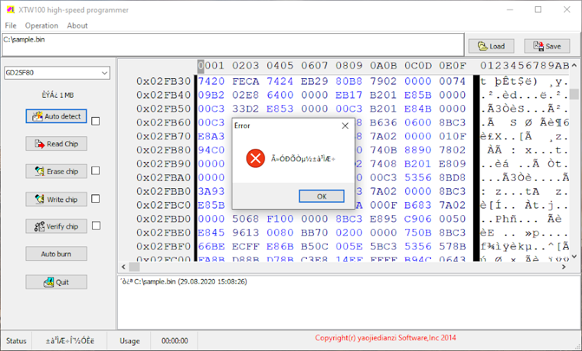
XTW100 programming software
There is also a PDF user manual written in Chinese. Basically, to read a memory chip, you launch the software and press Auto detect button for SPI flash placed in the closer to USB port half of the socket, with pin 1 aligned to socket handle. For I2C EEPROM, select the correct device in the combobox and place the chip in the other half of the socket, the one next to the handle, with pin 1 aligned to it. Then press Read chip button and wait for the buffer (right hexadecimal display pane) to fill with data. Use the Save button to save binary data.
To write a chip, you first have to Load binary data, then select I2C memory or auto detect SPI flash and click Write chip button. If the size of the data to write does not match chip capacity, additional data will be discarded.
There are some check boxes next to some of the buttons. Check them and then use Auto burn to perform all checked actions. Note that the interface does not respond during longer operations. Wait for it.
Xtw100 driver windows 10
XTW100 is a new SPI/I2C memory programmer based on STM32 microcontroller. It is advertised as a comprehensive replacement for the CH341A.
I recently found a new serial programmer, the XTW100 Mini Programmer which is supposed to be an «upgraded» variant of the well-known CH341A Mini Programmer. Having a similar price to CH341A, I didn’t wait any longer and ordered myself one. With a PCB slightly bigger (in length) than the PCB of CH341A, this new device is built around an STM32 ARM microcontroller. Having native USB port and hardware I2C and SPI, these microcontrollers with proper firmware could do a good job for this purpose.
Yet, there are some advertised features of this programmer that seem to good to be true (for a 4 USD programmer). Just as I did with the CH341A, I will try to draw the schematic and look for drivers and software for this XTW100 memory programmer. Because the STM32 is a 3.3 V device I can say for sure that this programmer will not have the 5 V bus levels issue. I got my XTW100 from AliExpress / WAVGAT store.

Product photo of XTW100 programmer
It is claimed that this programmer is able to switch supply voltage for the memory between 3.3 V and 5 V depending on the selected chip. Besides this, the software includes 1.8 V chips in its known devices list. We’ll see whether this voltage switching is true or not. However, I’m still struggling to understand what they mean with «Chip supports wireless enhancement» .
Hardware
The programmer is built around STM32F103C8T6 ARM 32-bit microcontroller. This and a linear voltage regulator (AMS1117-3.3) are the only integrated circuits on the PCB. I’m still wondering how they switch voltages. From the first look I can see this one does not have additional pin headers like CH341A has. Those connectors for serial port and SPI port proved useful for me and definitely make the programmer more versatile. Unfortunately, XTW100 does not feature similar ports.
Note that the same microcontroller is used by «blue pill» development boards. STM32F103C8 is a device with Cortex-M3 ARM CPU that runs at maximum 72 MHz, 20 kB of RAM and 64 kB of flash memory. The microcontroller (MCU) has USB port, two serial ports, 16-bit PWM pins and 12 bit ADC pins. It runs at 3.3V, but some of its pins are 5V tolerant.
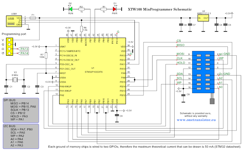
Schematic of XTW100 MinProgrammer
With a multimeter and a couple of hours I was able to trace the schematic of this programmer. First of all, as I supposed, this is a 3.3 V device. SPI bus is wired to a hardware SPI port of the STM32 (SPI2 on pins PB12..PB15). That’s a good thing. It means good overall transfer rates with the highest available SPI clock frequency on this MCU (18 MHz) — if configured by software.
With I2C they chose a totally different configuration. While I2C1 pins PB6 and PB7 are used to drive the LEDs, I2C2 pins PB10 and PB11 are used as GPIOs to provide ground connection for the SPI memory, there is no hardware port available for I2C. It must be implemented in software, but that’s no big deal.
Strange way of powering the memory chips though. 3.3 V supply is coming from the voltage regulator which also powers the CPU, yet the ground is controlled by software. Two GPIO pins for each memory chip are pulled down to create the voltage that will power memory ICs. In this way the current through any chip you may plug in the programmer is limited to 2 x 25 mA/pin = 50 mA. This limitation is a bit dangerous. Draw more and you may destroy those pins of the GPIO or the entire port if you’re «lucky».
Current limiting is good for in-circuit programming, where you could end up powering more than the memory chip. But it should have been designed in a different way, not relying on the microcontroller to power chips from GPIOs.
These being said, I can’t figure how could they use different voltage levels. Keep in mind that many 5 V serial memory chips are also 3.3 V compatible, so this programmer could be very well used for them. But that’s a totally different thing from «The programming voltage is automatically switched».
Driver
This programmer has been initially designed and manufactured by Zigong yaojie Electronic technology Co., Ltd. They also provide software and driver for download. Although the software package is last updated in 2019, the driver is not digitally signed and will not install seamlessly on Windows 10.
Fortunately, their driver is nothing more than a libwdi generated INF file which uses libusb. So, get Zadig and install libusb-win32 driver (important: only this one works with their programming software) for the WinUSBComm Device with the specific IDs 1FC8:300B . Proceed with caution in order not to replace the driver of another USB device.
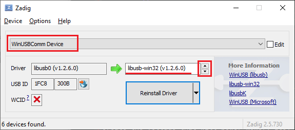
Install libusb-win32 driver for XTW100
Follow-up
Is it worth switching from CH341A to XTW100? Well, it’s a good addition to my toolbox, but I’m not sure it can replace CH341A Mini Programmer. In a follow-up post (I actually bricked its firmware) I’ll actually use it and sample the buses with a logic analyzer.
